A scheduler cannot give a UE just any number of resource blocks. The allowed sizes depend on the direction, on the system bandwidth and on the resource allocation type. In the downlink, the RBG size sets the step for resource allocation type 0. In the uplink, the DFT of SC-FDMA decides which sizes exist at all. Let's take the downlink first, then the RB count of each bandwidth, and then the uplink.
- Why does the DL allocation follow the RBG size ?
- How many RBs does each system bandwidth have ?
- Which UL RB sizes are allowed ?
- Reference
Why does the DL allocation follow the RBG size ?
Resource allocation type 0 does not address single resource blocks. It addresses Resource Block Groups with a bitmap, one bit per RBG, so the DCI stays small even in a 100 RB cell. The price is granularity. The UE can only get whole RBGs, and the list below gives the resulting step for each bandwidth.
For Resource Allocation Type 0 which is the most common resource allocation type, there is a rules for DL_RB setting
- if System BW = 1.4 M, it should be multiples of 1 (1 x n)
- if System BW = 3 M, it is should be multiples of 2 (2 x n)
- if System BW = 5 M, it should be multiples of 2 (2 x n)
- if System BW = 10 M,it should be multiples of 3 (3 x n)
- if System BW = 15 M, it should be multiples of 4 (4 x n)
- if System BW = 20 M, it should be multiples of 4 (4 x n)
This rule is derived from the Resource Block Group(RBG) size for each bandwidth, and the RBG size for system bandwidth is shown in TS 36.213 Table 7.1.6.1-1. (Number of DL RB should should be the multiples of RBG for the corresponding system bandwidth)
< 36.213 - Table 7.1.6.1-1: Type 0 resource allocation RBG size vs. Downlink System Bandwidth >
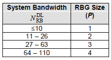
The rule "multiples of P" holds for most allocations, with one exception. 36.213 v19.4.0 clause 7.1.6.1 divides the bandwidth into ⌈NRBDL/P⌉ RBGs. When NRBDL is not a multiple of P, the last RBG is smaller than P. So an allocation that includes the last RBG can be one, two or three RBs short of a multiple of P. The table below applies this to the six LTE bandwidths.
< RBG count and last RBG size for type 0, based on 36.213 v19.4.0 Table 7.1.6.1-1 >
Channel bandwidth | NRBDL | RBG size P | Number of RBGs | Size of the last RBG |
1.4 MHz | 6 | 1 | 6 | 1 |
3 MHz | 15 | 2 | 8 | 1 |
5 MHz | 25 | 2 | 13 | 1 |
10 MHz | 50 | 3 | 17 | 2 |
15 MHz | 75 | 4 | 19 | 3 |
20 MHz | 100 | 4 | 25 | 4 |
Take a 10 MHz cell as an example. It has 50 RBs and P = 3. RBG 0 to RBG 15 hold 3 RBs each, and RBG 16 holds the remaining 2. The bitmap therefore has 17 bits. An allocation of RBG 15 and RBG 16 is 5 RBs, which is not a multiple of 3. The RBGs are indexed in increasing frequency, so the short RBG is always the one at the top of the band.
The other two DL types relax the rule. Type 1 splits the RBGs into P subsets and addresses single VRBs inside one subset. Type 2 assigns a run of contiguous VRBs with a start and a length. So a localized allocation with DCI format 1A can have any length from 1 RB up to the bandwidth. The multiples of P rule therefore belongs to type 0 only. Short TTI is a separate case. With DCI formats 7-1A to 7-1G it uses Table 7.1.6.1-1A, with RBG sizes of 1, 2, 6 and 12.
The RBG size depends only on the bandwidth : P is 1, 2, 3 or 4 for 10 or fewer, 11 to 26, 27 to 63 and 64 to 110 downlink RBs.The last RBG can be short : at 3, 5, 10 and 15 MHz it holds 1, 1, 2 and 3 RBs, so an allocation that includes it is not a multiple of P.Only type 0 is bound to whole RBGs : type 1 and type 2 can address single resource blocks.
How many RBs does each system bandwidth have ?
The RBG rule and the UL rule both start from NRB, the number of resource blocks in the channel. That number is not the channel bandwidth divided by 180 kHz. Part of every channel is guard band, and the specification fixes the usable part as the transmission bandwidth configuration.
* Reference for additional restriction and details :
TS 36.104 Table 5.6.1 for DL (Number of RBs for each System BW),
< Table 5.6-1 Transmission bandwidth configuration NRB in E-UTRA channel bandwidths >
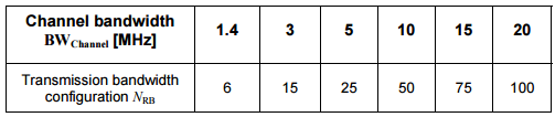
The table above is the base station side. 36.101 v20.0.0 Table 5.6-1 gives the same six values for the UE, so both ends agree on NRB for a given channel. The same numbers apply to the uplink. The occupied part of the channel is NRB x 180 kHz. For example, 100 RBs in a 20 MHz channel occupy 18 MHz, so 90 percent of the channel carries resource blocks. The 1.4 MHz channel has the largest share of guard band. Its 6 RBs occupy only 1.08 MHz.
NRB is fixed for each channel bandwidth : 6, 15, 25, 50, 75 and 100 RBs for 1.4, 3, 5, 10, 15 and 20 MHz.The eNB and the UE use the same table : 36.104 and 36.101 both define Table 5.6-1 with the same values.
Which UL RB sizes are allowed ?
The uplink has a different kind of limit. PUSCH uses SC-FDMA, so the UE applies a DFT, the transform precoding, to all its allocated subcarriers before the IFFT. 36.211 allows only DFT sizes that factor into 2, 3 and 5, because such DFTs are cheap to implement. This becomes a rule on the number of RBs.
TS 36.211 Section 5.3.3 for UL. Number of UL RB should meet the following requirement.

Possible Number of RBs for UL : (Due to the rules stated in TS 36.211 Section 5.3.3. You can only have following numbers which can be used for UL)
1,2,3,4,5,6,8,9,10,12,15,16,18,20,24,25,27,30,32,36,40,45,48,50,54,60,64,72,75,80,81,90,96,100
The list is every number 2α2 x 3α3 x 5α5 up to 100, where the three exponents are non-negative integers. So a UE in a 20 MHz cell can get 96 or 100 RBs, but never 97, 98 or 99. The formula also gives 108, but no LTE bandwidth has more than 100 uplink RBs.
In practice, the full width is rarely available. PUCCH normally occupies RBs at both edges of the uplink band, so the PUSCH region of a 20 MHz cell is smaller than 100 RBs. The scheduler then picks an allowed size that fits, for example 96 RBs. Uplink resource allocation type 1, from Release 10, gives the UE two sets of RBGs. The transform precoding still counts all allocated RBs together, so the total must still be a number from the list.
The UL sizes come from the DFT : every PUSCH allocation is 2α2 x 3α3 x 5α5 RBs.The DL and UL rules have different reasons : the DL rule keeps the DCI bitmap small, and the UL rule keeps the DFT cheap.Some sizes near the top are missing : above 81 RBs, only 90, 96 and 100 are allowed.
Reference
- 36.213 : 3GPP - E-UTRA Physical layer procedures, v19.4.0. Clauses 7.1.6.1 to 7.1.6.3, Table 7.1.6.1-1, Table 7.1.6.1-1A and clause 8.1.2.
- 36.211 : 3GPP - E-UTRA Physical channels and modulation, v19.3.0. Clause 5.3.3, Transform precoding.
- 36.101 : 3GPP - E-UTRA User Equipment (UE) radio transmission and reception, v20.0.0. Table 5.6-1.
- 36.104 : 3GPP - E-UTRA Base Station (BS) radio transmission and reception. Table 5.6-1, as quoted in the image on this page.