A PDN or PDU session needs more than an IP address. The UE also needs DNS server addresses, a P-CSCF address for IMS, an MTU value, and sometimes a set of PPP negotiation options. None of these has a dedicated NAS information element, so 3GPP carries all of them in a single container. Protocol Configuration Options (PCO) is a component of NAS message and this component can be carried by many different messages as follows.
- PDN Connectivity Request (LTE)
- ActivateDefaultEPSBearerContextRequest (LTE)
- ActivateDefaultEPSBearerContextAccept (LTE)
- PDU session establishment request (NR)
- PDU session establishment accept (NR)
Followings are the list of the details on PCO :
- Data Structure of PCO
- Where PCO Appears in Signaling
- How Network Configure PCO ?
- Example 1 - PDN Connectivity
- Example 2 - PDN Connectivity
- Example 3 - PDN Connectivity
- Example 4 - PDN Connectivity
- Example 5 - PDU Establishment
- Reference
Data Structure of PCO
The element has to hold items that were never designed together. Some entries are PPP protocols listed in RFC 3232, and the rest are 3GPP container IDs defined in 24.008. Both kinds sit in the same field, and only the value of the ID says which family an entry belongs to. Data Structure of PCO is very flexible (complicated) which may give a lot of difficulties in message decoding process. The structure is as follows.
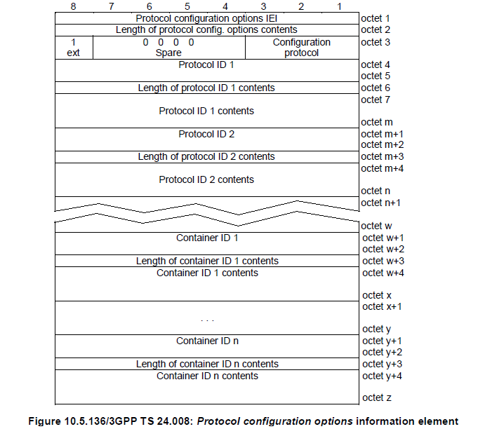
Figure 1. The PCO information element, from 24.008 Figure 10.5.136. A fixed header of three octets, then a variable number of entries that each describe their own length.
Octet 1 is the PCO IEI. It reads 0x27 in every LTE example on this page.Octet 2 is the length of the contents that follow it. Octets 1 and 2 are not counted in that length.Octet 3 carries three fields. The ext bit is set to 1, three spare bits are set to 0, and a three bit Configuration protocol field follows. The value 0 means PPP for use with IP PDP type or IP PDN type, and it is the only value in use.Octet 4 onward is a repeating triple of ID, length of contents, and contents. The figure draws the Protocol ID entries first and the Container ID entries after them, with a zigzag break standing for any number of further entries.Bit numbering runs 8 down to 1 across the top of each octet, which is the 24.008 convention. A decoder that assumes the opposite order will read the ext bit and the Configuration protocol field in the wrong place.
There are various Container ID as shown below. The list would get longer and longer as specification evolves.
NOTE : These are only some of the container IDs that are commonly used based on my experience. There are many more in the specification. Check out 24.008-10.5.6.3 for the complete list.
|
Container ID |
Description (Network to MS Direction) |
|
0001H |
P-CSCF IPv6 Address |
|
0002H |
IM CN Subsystem Signaling Flag |
|
0003H |
DNS Server IPv6 Address |
|
0004H |
Policy Control rejection code |
|
0005H |
Selected Bearer Control Mode; |
|
0006H |
Reserved |
|
0007H |
DSMIPv6 Home Agent Address |
|
0008H |
DSMIPv6 Home Network Prefix |
|
0009H |
DSMIPv6 IPv4 Home Agent Address |
|
000AH |
reserved |
|
000BH |
reserved |
|
000CH |
P-CSCF IPv4 Address |
|
000DH |
DNS Server IPv4 Address |
|
000EH |
MSISDN |
|
000FH |
IFOM-Support |
|
0010H |
IPv4 Link MTU |
|
0011H |
Network support of Local address in TFT indicator |
|
0012H |
Reserved |
|
0013H |
NBIFOM accepted indicator |
|
0014H |
NBIFOM mode |
|
0015H |
Non-IP Link MTU |
|
0016H |
APN rate control parameters |
|
0017H |
3GPP PS data off support indication |
|
0018H |
Reliable Data Service accepted indicator |
|
0019H |
Additional APN rate control for exception data parameters |
|
001AH |
reserved |
|
001BH |
S-NSSAI |
|
001CH |
QoS rules |
|
001DH |
Session-AMBR |
|
001EH |
PDU session address lifetime |
|
001FH |
QoS flow descriptions |
|
0020H |
Ethernet Frame Payload MTU |
|
0021H |
Unstructured Link MTU |
|
0022H |
reserved |
|
0023H |
QoS rules with the length of two octets |
|
0024H |
QoS flow descriptions with the length of two octets |
|
0025H |
Small data rate control parameters |
|
0026H |
Additional small data rate control for exception data parameters |
|
0027H |
ACS information |
|
0028H |
Initial small data rate control parameters |
|
0029H |
Initial additional small data rate control for exception data parameters |
|
002AH |
Initial APN rate control parameters |
|
002BH |
Initial additional APN rate control for exception data parameters |
|
0030H |
ATSSS response with the length of two octets |
|
0031H |
DNS server security information with length of two octets |
|
0032H |
ECS address with the length of two octets |
|
0035H |
ECSP identifier |
|
0036H |
PVS IPv4 Address |
|
0037H |
PVS IPv6 Address |
|
0038H |
PVS name |
|
0039H |
reserved |
|
003AH |
EAS rediscovery indication without indicated impact |
|
003BH |
EAS rediscovery indication with impacted EAS IPv4 address range |
|
003CH |
EAS rediscovery indication with impacted EAS IPv6 address range |
|
003DH |
EAS rediscovery indication with impacted EAS FQDN |
|
003EH |
Uplink data not allowed |
|
003FH |
Uplink data allowed |
|
0040H |
UAS services not allowed indication |
|
0041H |
Service-level-AA container with the length of two octets |
|
0047H |
Reserved |
|
0048H |
EDC usage allowed indicator |
|
0049H |
EDC usage required indicator |
|
004AH |
Network support of MAC address range in 5GS indicator |
|
0050H |
Reserved |
|
0051H |
SDNAEPC EAP message with the length of two octets |
|
0052H |
Reserved |
|
0056H |
UE policy container with the length of two octets |
|
0057H |
URSP provisioning in EPS support indicator |
|
0058H |
Reserved |
|
0059H |
Reserved |
|
0060H |
Reserved |
|
0061H |
NSSAA EAP message with the length of two octets |
|
0062H |
NSSAA status |
|
C021H |
LCP (refer to RFC 3232) |
|
C023H |
PAP (refer to RFC 3232) |
|
C223H |
CHAP (refer to RFC 3232) |
|
8021H |
IPCP (refer to RFC 3232) |
|
FF00H to FFFFH |
Reserved for operator specific use. |
The table gives the names used in the network to MS direction, as its header says. Many IDs carry a different name in the other direction, because the UE asks and the network answers. For example, 0001H is P-CSCF IPv6 Address Request when the UE sends it and P-CSCF IPv6 Address when the network sends it, and 000EH is MSISDN Request against MSISDN. The rows from 0050H to 0062H come from 24.008 v20.0.0. They serve SDNAEPC, the URSP and UE policy transfer in EPS, and network slice-specific authentication over EPC. The gaps in the numbering, such as 002CH to 002FH or 0042H to 0046H, are not assigned in that version.
One worked example makes the layout concrete. The hex string below is a complete PCO information element, and the breakdown under it takes the octets in the order a decoder meets them.
Example 1 : 271B80802110030000108106C0A801028306C0A80102000D04C0A80102

    Octet 1 (Protocol Configuration Option IEI): 27H
    Octet 2 (Length of protocol configuration options contents): 1BH=27
    Octet 3 : 80H = 10000000b
        ext = 1
        spare = 0000
        Configuration Protocol = 000
    Octet 4-253 : 802110030000108106C0A801028306C0A80102000D04C0A80102
        Protocol ID 1 : 8021H (IPCP)
        Length of Protocol ID 1 Contents : 10H=16
        Protocol ID 1 Contents = 030000108106C0A801028306C0A80102H
        Protocol ID 2 : 0004H(DNS)
        Length of Protocol ID 2 Contents : 04H=4
        Protocol ID 2 Contents = C0A80102H
Three octets of header, then a list : the IEI, the length and the ext/spare/Configuration protocol octet are fixed, and everything after them is a repeating entry.Every entry carries its own length : a decoder walks the element from entry to entry, and an unknown ID is skipped by its length rather than stopping the parse.Two families share one ID field : the PPP protocol IDs listed in RFC 3232 and the 3GPP container IDs of 24.008 sit in the same field. Only the value distinguishes them.The list keeps growing : the container IDs in the table above are the common ones, and 24.008 clause 10.5.6.3 holds the complete and current set.
Where PCO Appears in Signaling
The examples above show PCO in two messages, and that is the smallest view of it. The element is optional in twenty of the twenty-five LTE session management messages, and in fifteen of the nineteen 5G ones. It can therefore arrive at any point in the life of a session. It also travels further than a log on any single interface shows. This section covers who the two ends are, which messages carry the element, and why an attach takes a detour before the UE can send it.
The two ends are the UE and the gateway
A NAS log shows PCO passing between the UE and the MME, and reading that as the endpoints is the first mistake to avoid. In EPS the two ends are the UE and the PDN GW (24.301 clause 6.6.1.1). In 5GS they are the UE and the SMF (24.501 clause 6.6.1). Every node between them forwards the element without interpreting it.
Figure 2 sets the EPS path beside the 5GS one. The nodes drawn in grey carry the element across their own interfaces and hand it on unchanged.
Figure 2. PCO is an end to end container. Only the two boxes at the edges read it, and the ones between them relay it across S1, S11 and S5, or across N1 and N11.
One consequence is worth carrying into a debug session. A container the UE requested and never received is a gateway decision, so the log to pull is on the PDN GW or the SMF. A trace taken at the MME or the AMF shows only that the element passed through, and it will never explain why a container is missing.
EPS has a second possible peer. 24.301 clause 6.6.1.3 allows the SCEF to be the node that inserts PCO, and that is the path used for non-IP data delivery.
Which messages carry it
Treating PCO as an attach-time element is the second mistake, and it is the one that hides live configuration changes. The IE is optional across nearly the whole session management protocol, not only in the two messages that set a session up.
In LTE it appears in the activate, modify and deactivate messages for both default and dedicated bearers. It appears again in the bearer resource allocation and modification pairs, in PDN connectivity and PDN disconnect, and in ESM INFORMATION RESPONSE. Five ESM messages do without it : ESM INFORMATION REQUEST, ESM STATUS, REMOTE UE REPORT, REMOTE UE REPORT RESPONSE and ESM DATA TRANSPORT. In 5G the element sits in fifteen 5GSM messages, from PDU session establishment through modification to release.
That reach matters when a session changes after it is up. A network can add a container in a MODIFY EPS BEARER CONTEXT REQUEST hours into a session. A UE that only parses PCO during attach will miss it. 3GPP PS data off is the clearest case. The UE reports its status in PCO during attach and PDN connectivity, and it signals every later change through the bearer resource modification procedure.
The same reach explains why the container list on this page keeps growing. Edge computing is a recent example. The SMF hands the UE the address of an EASDF as the DNS server for the PDU session, and it does so inside the ePCO (24.501 clause 6.2.17).
Why the attach takes a detour
Example 3 opens with a flag that carries no PCO content at all, and it decides where the PCO will travel. The line reads EIT (ESM information transfer): Security protected ESM information transfer required, and the reason behind it is ciphering.
On initial attach the PDN CONNECTIVITY REQUEST rides inside the ATTACH REQUEST, and no NAS security context exists at that moment. Anything sent there crosses the air interface in the clear, and a PCO can hold an APN, a CHAP exchange or an MSISDN. The UE therefore sets the ESM information transfer flag, and that asks the MME to collect the element again once ciphering is on.
The MME sends ESM INFORMATION REQUEST only after the security context is set up, and only when that flag was present (24.301 clause 6.6.1.2.2). It starts timer T3489 and waits for ESM INFORMATION RESPONSE, and the UE puts the protected PCO and the APN in that message.
Figure 3 places the procedure inside the attach. The green line marks the point where ciphering starts, and the two GTP legs show where the element leaves NAS.
Figure 3. The ESM information request procedure exists so the PCO crosses the air interface ciphered. Everything below the green line is protected, and the PCO collected there is the copy the P-GW acts on.
One rule decides which copy counts. A PCO in the ESM INFORMATION RESPONSE replaces any PCO the network received earlier in the same attach (24.301 clause 6.6.1.2.4). A decode that shows the element twice is therefore normal, and the second one is the one that reaches the gateway.
The procedure has a failure mode worth recognising in a log. T3489 is retried twice. On the third expiry the MME abandons the attempt, and it answers with PDN CONNECTIVITY REJECT carrying ESM cause #53, ESM information not received. A reject with that cause points at the detour rather than at the contents of the PCO.
5G has no equivalent step, and the order of the procedures is the reason. A PDU session is established from 5GMM-REGISTERED state, so the NAS security context already exists when the PDU SESSION ESTABLISHMENT REQUEST is sent. The ePCO is protected from the first message, and nothing has to be fetched a second time.
PCO or ePCO
Example 5 carries Extended protocol configuration options rather than PCO, and that is not simply a 5G rename of the same thing. In EPS both forms exist, and the network and the UE have to agree on which one is in use for a PDN connection.
The difference sits in the header rather than in the payload. PCO is a type 4 IE with a maximum length of 253 octets, and one octet holds its length. The extended form is a type 6 IE with a maximum length of 65538 octets, and two octets hold its length. The contents are coded identically in both, so a decoder needs one container parser and two header cases.
In EPS the choice is negotiated during attach. The UE sets the ePCO bit in the UE network capability IE of the ATTACH REQUEST. The MME sets the same bit in the EPS network feature support IE of the ATTACH ACCEPT. Three cases force ePCO whatever the bits say : NB-S1 mode, an APN for UAS services, and a PDN type of non-IP or Ethernet.
In 5GS there is no negotiation and no fallback. The extended form is the only one available, and that is why every container in Example 5 arrives in it.
The ends are the UE and the gateway : PCO terminates at the PDN GW in EPS and at the SMF in 5GS. A missing container is a gateway decision rather than an MME or AMF one.It is not an attach-only element : twenty ESM messages and fifteen 5GSM messages can carry it, so a container can arrive during a modification long after the session came up.The EIT flag moves the PCO : it asks the MME to collect the element again after ciphering is on, and the copy in ESM INFORMATION RESPONSE replaces the earlier one.ESM cause #53 points at that detour : three expiries of T3489 turn a missing ESM INFORMATION RESPONSE into a PDN CONNECTIVITY REJECT, with nothing wrong in the PCO itself.ePCO changes the header, not the payload : 253 octets become 65538 and the container encoding is unchanged, and EPS negotiates the choice while 5GS always uses ePCO.
How Network Configure PCO ?
The simplest answer is "It is completely up to Network !", but one common scenario is "It sends whatever requested by PCO from UE" as shown below.
i) UE --> NW : PCO in PDN Connectivity Request (UE request the information it want to get)
ii) UE <-- NW : PCO in Activate Default EPS Bearer Request (NW informs UE of what it want)
Example 1 - PDN Connectivity
In this example, what NW sends in PCO matches exactly what UE requested in PCO. Two things are worth noticing here. The UE sends its DNS options inside IPCP with both addresses set to 0.0.0.0. That is how PPP asks the peer for a value. The network answers with a Configuration Nak carrying the real addresses, then repeats the same addresses in container 0x000d.
Element ID: 0x27 Length: 26 [Link direction: MS to network (0)] 1... .... = Extension: True Configuration Protocol: PPP for use with IP PDP type or IP PDN type (0)Protocol or Container ID: Internet Protocol Control Protocol (0x8021) Length: 0x10 (16) PPP IP Control Protocol Code: Configuration Request (1) Identifier: 0 (0x00) Length: 16 Options: (12 bytes), Primary DNS Server IP Address, Secondary DNS Server IP Address Primary DNS Server IP Address: 0.0.0.0 Type: Primary DNS Server IP Address (129) Length: 6 Primary DNS Address: 0.0.0.0 (0.0.0.0) Secondary DNS Server IP Address: 0.0.0.0 Type: Secondary DNS Server IP Address (131) Length: 6 Secondary DNS Address: 0.0.0.0 (0.0.0.0)Protocol or Container ID: DNS Server IPv4 Address Request (0x000d) Length: 0x00 (0)Protocol or Container ID: IP address allocation via NAS signalling (0x000a) Length: 0x00 (0)
    Element ID: 0x27
    Length: 27
    [Link direction: Network to MS (1)]
    1... .... = Extension: True
    Configuration Protocol: PPP for use with IP PDP type or IP PDN type (0)
    Protocol or Container ID: Internet Protocol Control Protocol (0x8021)
        Length: 0x10 (16)
        PPP IP Control Protocol
            Code: Configuration Nak (3)
            Identifier: 0 (0x00)
            Length: 16
            Options: (12 bytes), Primary DNS Server IP Address, Secondary DNS Server IP Address
                Primary DNS Server IP Address: 192.168.1.2
                    Type: Primary DNS Server IP Address (129)
                    Length: 6
                    Primary DNS Address: 192.168.1.2 (192.168.1.2)
                Secondary DNS Server IP Address: 192.168.1.2
                    Type: Secondary DNS Server IP Address (131)
                    Length: 6
                    Secondary DNS Address: 192.168.1.2 (192.168.1.2)
    Protocol or Container ID: DNS Server IPv4 Address (0x000d)
        Length: 0x04 (4)
        IPv4: 192.168.1.2
Example 2 - PDN Connectivity
In this example, what NW sends in PCO matches roughly what UE requested in PCO, but in detail some of the information (e.g, CSCF IPv6 address) is missing. However, UE may accept this.
    Element ID: 0x27
    Length: 35
    [Link direction: MS to network (0)]
    1... .... = Extension: True
    Configuration Protocol: PPP for use with IP PDP type or IP PDN type (0)
    Protocol or Container ID: Internet Protocol Control Protocol (0x8021)
        Length: 0x10 (16)
        PPP IP Control Protocol
            Code: Configuration Request (1)
            Identifier: 0 (0x00)
            Length: 16
            Options: (12 bytes), Primary DNS Server IP Address, Secondary DNS Server IP Address
                Primary DNS Server IP Address: 0.0.0.0
                    Type: Primary DNS Server IP Address (129)
                    Length: 6
                    Primary DNS Address: 0.0.0.0 (0.0.0.0)
                Secondary DNS Server IP Address: 0.0.0.0
                    Type: Secondary DNS Server IP Address (131)
                    Length: 6
                    Secondary DNS Address: 0.0.0.0 (0.0.0.0)
    Protocol or Container ID: DNS Server IPv4 Address Request (0x000d)
        Length: 0x00 (0)
    Protocol or Container ID: DNS Server IPv6 Address Request (0x0003)
        Length: 0x00 (0)
    Protocol or Container ID: P-CSCF IPv6 Address Request (0x0001)
        Length: 0x00 (0)
    Protocol or Container ID: P-CSCF IPv4 Address Request (0x000c)
        Length: 0x00 (0)
    Element ID: 0x27
    Length: 15
    [Link direction: Network to MS (1)]
    1... .... = Extension: True
    Configuration Protocol: PPP for use with IP PDP type or IP PDN type (0)
    Protocol or Container ID: Internet Protocol Control Protocol (0x8021)
        Length: 0x04 (4)
        PPP IP Control Protocol
            Code: Configuration Nak (3)
            Identifier: 0 (0x00)
            Length: 4
    Protocol or Container ID: P-CSCF IPv4 Address (0x000c)
        Length: 0x04 (4)
        IPv4: 192.168.137.1
Example 3 - PDN Connectivity
This is the plain case, and it is the one to hold as the reference. The UE asks for three containers, 0x000d, 0x000a and 0x0010, and only 0x000d comes back inside PCO. The request for 0x000a was still honoured, because the address it asks for arrives in the PDN address IE rather than in PCO. The MTU request drew no answer at all, and no cause value explains that.
NAS EPS session management messages: PDN connectivity request (0xd0)0001 .... = PDN type: IPv4 (1) .... 0001 = Request type: initial request (1) ESM information transfer flag 1101 .... = Element ID: 0xd- .... 000. = Spare bit(s): 0x00 .... ...1 = EIT (ESM information transfer): Security protected ESM information transfer requiredProtocol Configuration Options Element ID: 0x27 Length: 29 [Link direction: MS to network (0)] 1... .... = Extension: True Configuration Protocol: PPP for use with IP PDP type or IP PDN type (0)Protocol or Container ID: Internet Protocol Control Protocol (0x8021) Length: 0x10 (16) PPP IP Control Protocol Code: Configuration Request (1) Identifier: 0 (0x00) Length: 16 Options: (12 bytes), Primary DNS Server IP Address, Secondary DNS Server IP Address Primary DNS Server IP Address: 0.0.0.0 Type: Primary DNS Server IP Address (129) Length: 6 Primary DNS Address: 0.0.0.0 (0.0.0.0) Secondary DNS Server IP Address: 0.0.0.0 Type: Secondary DNS Server IP Address (131) Length: 6 Secondary DNS Address: 0.0.0.0 (0.0.0.0)Protocol or Container ID: DNS Server IPv4 Address Request (0x000d) Length: 0x00 (0) Protocol or Container ID: IP address allocation via NAS signalling (0x000a) Length: 0x00 (0) Protocol or Container ID: IPv4 Link MTU Request (0x0010) Length: 0x00 (0)
NAS EPS session management messages: Activate default EPS bearer context request (0xc1)
EPS quality of service
    Length: 1
    Quality of Service Class Identifier (QCI): QCI 9 (9)
Access Point Name
    Length: 12
    APN: nxtgenphone
PDN address
    Length: 5
    0000 0... = Spare bit(s): 0x00
    PDN type: IPv4 (1)
    PDN IPv4: 192.168.1.1 (192.168.1.1)
Protocol Configuration Options
    Element ID: 0x27
    Length: 27
    [Link direction: Network to MS (1)]
    1... .... = Extension: True
    Configuration Protocol: PPP for use with IP PDP type or IP PDN type (0)
    Protocol or Container ID: Internet Protocol Control Protocol (0x8021)
        Length: 0x10 (16)
        PPP IP Control Protocol
            Code: Configuration Nak (3)
            Identifier: 0 (0x00)
            Length: 16
            Options: (12 bytes), Primary DNS Server IP Address, Secondary DNS Server IP Address
                Primary DNS Server IP Address: 192.168.1.2
                    Type: Primary DNS Server IP Address (129)
                    Length: 6
                    Primary DNS Address: 192.168.1.2 (192.168.1.2)
                Secondary DNS Server IP Address: 192.168.1.2
                    Type: Secondary DNS Server IP Address (131)
                    Length: 6
                    Secondary DNS Address: 192.168.1.2 (192.168.1.2)
    Protocol or Container ID: DNS Server IPv4 Address (0x000d)
        Length: 0x04 (4)
        IPv4: 192.168.1.2
Example 4 - PDN Connectivity
Example 4 is the one to study, because the response is shaped by a decision taken outside PCO. The UE requests PDN type IPv4v6 on the ims APN and asks for six containers, three tied to IPv4, two tied to IPv6 and one neutral. The network answers with ESM cause 51, PDN type IPv6 only allowed, and assigns an IPv6 address. Every IPv4 container then disappears from the response, IPCP included, and only the two IPv6 containers come back.
NAS EPS session management messages: PDN connectivity request (0xd0)
0011 .... = PDN type: IPv4v6 (3)
.... 0001 = Request type: initial request (1)
Access Point Name
    Element ID: 0x28
    Length: 4
    APN: ims
Protocol Configuration Options
    Element ID: 0x27
    Length: 38
    [Link direction: MS to network (0)]
    1... .... = Extension: True
    Configuration Protocol: PPP for use with IP PDP type or IP PDN type (0)
    Protocol or Container ID: Internet Protocol Control Protocol (0x8021)
        Length: 0x10 (16)
        PPP IP Control Protocol
            Code: Configuration Request (1)
            Identifier: 0 (0x00)
            Length: 16
            Options: (12 bytes), Primary DNS Server IP Address, Secondary DNS Server IP Address
                Primary DNS Server IP Address: 0.0.0.0
                    Type: Primary DNS Server IP Address (129)
                    Length: 6
                    Primary DNS Address: 0.0.0.0 (0.0.0.0)
                Secondary DNS Server IP Address: 0.0.0.0
                    Type: Secondary DNS Server IP Address (131)
                    Length: 6
                    Secondary DNS Address: 0.0.0.0 (0.0.0.0)
    Protocol or Container ID: DNS Server IPv4 Address Request (0x000d)
        Length: 0x00 (0)
    Protocol or Container ID: DNS Server IPv6 Address Request (0x0003)
        Length: 0x00 (0)
    Protocol or Container ID: P-CSCF IPv6 Address Request (0x0001)
        Length: 0x00 (0)
    Protocol or Container ID: P-CSCF IPv4 Address Request (0x000c)
        Length: 0x00 (0)
    Protocol or Container ID: IP address allocation via NAS signalling (0x000a)
        Length: 0x00 (0)
    Protocol or Container ID: IPv4 Link MTU Request (0x0010)
        Length: 0x00 (0)
NAS EPS session management messages: Activate default EPS bearer context request (0xc1)
EPS quality of service
    Length: 1
    Quality of Service Class Identifier (QCI): QCI 5 (5)
Access Point Name
    Length: 4
    APN: ims
PDN address
    Length: 9
    0000 0... = Spare bit(s): 0x00
    PDN type: IPv6 (2)
    PDN IPv6 if id: 0000000000000011
ESM cause
    Element ID: 0x58
    Cause: PDN type IPv6 only allowed (51)
Protocol Configuration Options
    Element ID: 0x27
    Length: 39
    [Link direction: Network to MS (1)]
    1... .... = Extension: True
    Configuration Protocol: PPP for use with IP PDP type or IP PDN type (0)
    Protocol or Container ID: DNS Server IPv6 Address (0x0003)
        Length: 0x10 (16)
        IPv6: 2001:0:0:1::2
    Protocol or Container ID: P-CSCF IPv6 Address (0x0001)
        Length: 0x10 (16)
        IPv6: 2001:0:0:1::2
Example 5 - PDU Establishment
Example 5 moves to 5G, and the container mechanism survives the move almost unchanged. The IE is now Extended protocol configuration options, so a container length may run to two octets rather than one. The UE asks for eleven entries. The pattern from Example 4 then repeats. The UE requests PDU session type IPv4v6, the network selects IPv4, gives 5GSM cause 0x32 for it, and returns only what an IPv4 session can use.
Protocol discriminator = 0x2e (5GS Session Management) PDU session identity = 1 Procedure transaction identity = 5 Message type = 0xc1 (PDU session establishment request) Integrity protection maximum data data: Maximum data rate per UE for user-plane integrity protection for uplink = 0x00 (64 kbps) Maximum data rate per UE for user-plane integrity protection for downlink = 0x00 (64 kbps) PDU session type = 0x3 (IPv4v6) 5GSM capability: 0x00 (TPMIC=0, ATSSS-ST=0, EPT-S1=0, MH6-PDU=0, RqoS=0)Extended protocol configuration options: Ext = 1 Configuration protocol = 0Protocol ID = 0xc223 (CHAP) Data = 01 00 00 16 10 11 f7 7e 7e 11 f7 7e 7e 11 f7 7e 7e 11 f7 7e 7e 2aProtocol ID = 0xc223 (CHAP) Data = 02 00 00 16 10 9a 62 f4 9f cd d9 60 54 7a a9 37 58 60 99 f0 77 2aProtocol ID = 0x8021 (IPCP) Data = 01 00 00 10 81 06 00 00 00 00 83 06 00 00 00 00Protocol ID = 0x000d (DNS Server IPv4 Address Request) Data =Protocol ID = 0x0003 (DNS Server IPv6 Address Request) Data =Protocol ID = 0x000a (IP address allocation via NAS signalling) Data =Protocol ID = 0x0005 (MS Support of Network Requested Bearer Control indicator) Data =Protocol ID = 0x0010 (IPv4 Link MTU Request) Data =Protocol ID = 0x0011 (MS support of Local address in TFT indicator) Data =Protocol ID = 0x0023 (QoS rules with the length of two octets support indicator) Data =Protocol ID = 0x0024 (QoS flow descriptions with the length of two octets support indicator) Data =
Protocol discriminator = 0x2e (5GS Session Management)
PDU session identity = 1
Procedure transaction identity = 5
Message type = 0xc2 (PDU session establishment accept)
Selected PDU session type = 0x1 (IPv4)
Selected SSC mode = 0x1 (1)
Authorized QoS rules:
  QoS rule 1:
    QoS rule identifier = 1
    Rule operation code = 1 (create new QoS rule)
    DQR = 1 (the QoS rule is the default QoS rule)
    Number of packet filters = 1
    Packet filter identifier = 15
      Packet filter direction = 3 (bidirectional)
      Match-all
    QoS rule precedence = 255
    QFI = 1
Session AMBR:
  Session-AMBR for downlink = 5000 Mbps
  Session-AMBR for uplink = 2000000 kbps
5GSM cause = 0x32 (PDU session type IPv4 only allowed)
PDU address:
  SI6LLA = 0
  PDU session type = 1 (IPv4)
  IPv4 = 192.168.3.2
S-NSSAI:
  Length of S-NSSAI contents = 1 (SST)
  SST = 0x01
Mapped EPS bearer contexts:
  Mapped EPS bearer context 1:
    EPS bearer identity = 5
    Operation code = 1 (create new EPS bearer)
    E = 1 (parameters list is included)
    Number of EPS parameters = 2
    Mapped EPS QoS parameters:
      QCI = 9
    APN-AMBR:
      APN-AMBR for downlink = 4864000000 bits
      APN-AMBR for uplink = 1792000000 bits
Authorized QoS flow descriptions:
  QoS flow description 1:
    QFI = 1
    Operation code = 1 (create new QoS flow description)
    E = 1 (parameters list is included)
    Number of parameters = 2
    5QI = 9
    EPS bearer identity = 5
Extended protocol configuration options:
  Ext = 1
  Configuration protocol = 0
  Protocol ID = 0x8021 (IPCP)
  Data = 03 00 00 0a 81 06 08 08 08 08
  Protocol ID = 0x000d (DNS Server IPv4 Address)
  Data = 8.8.8.8
DNN = "internet.mnc001.mcc001.gprs"
Reference
[1] 3GPP TS 24.008 v20.0.0 - Mobile radio interface Layer 3 specification; Core network protocols; Stage 3. Clause 10.5.6.3 defines the Protocol configuration options IE and clause 10.5.6.3A the extended form, and clause 10.5.6.3 also holds the full container ID list.
[2] 3GPP TS 24.301 - Non-Access-Stratum (NAS) protocol for Evolved Packet System (EPS); Stage 3. Clause 6.6.1 covers the exchange of protocol configuration options, and clause 8.3 lists the ESM messages that carry the IE.
[3] 3GPP TS 24.501 - Non-Access-Stratum (NAS) protocol for 5G System (5GS); Stage 3. Clause 6.6.1 places the two ends at the UE and the SMF, and clause 8.3 lists the 5GSM messages that carry the IE.
[4] 3GPP TS 29.274 - Evolved GPRS Tunnelling Protocol for Control plane (GTPv2-C); Stage 3. The transfer of the element between the MME, the S-GW and the PDN GW.