PUCCH Format 3 is relatively new format that is mainly used for carrier aggregation which uses 3 or more component carriers. It carries 48 coded bits in one subframe, far more than the 2 bits of format 1b. So one PUCCH can acknowledge the PDSCHs of several component carriers at once. Format 3 can also be configured in TDD with a single serving cell, where one uplink subframe acknowledges several downlink subframes.
The topics on this page are listed below.
- PUCCH Format 3 Location
- Signal Generation of PUCCH Format 3
- How does the UE know which PUCCH Format 3 resource to use?
- Reference
PUCCH Format 3 Location
Where in the band does a format 3 PUCCH sit? It follows the same edge-hopping rule as formats 1 and 2, so only the value of m changes. For format 3, m comes from the resource index nPUCCH(3,p) and from NSF,0PUCCH = 5, the spreading factor of the first slot. The PUCCH Format 2 page walks through the same equations with a divisor of 12.
PUCCH Format 3 - RB Mapping
The diagram below uses a 5 MHz grid with RB 0 at the bottom and RB 24 at the top. The grey box at the upper right is the Rel-10 ASN.1 that carries the resource index: n3PUCCH-AN-List-r10, and n3PUCCH-AN-ListP1-r10 for the second antenna port. The equations below the box take that index to m, and m to nPRB.
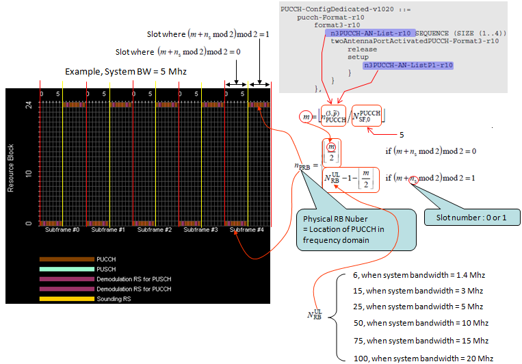
PUCCH format 3 RB mapping in a 5 MHz cell. The equation differs from format 2 only in the divisor, 5 instead of 12.
m = floor(nPUCCH(3,p) / NSF,0PUCCH) : the arrow marks NSF,0PUCCH as 5. So 5 consecutive resource values share one RB pair, one for each orthogonal sequence.p is the antenna port : with two antenna ports, the second port takes its own value from n3PUCCH-AN-ListP1-r10, so its m can differ.The slot rule is the same as format 2 : when (m + ns mod 2) mod 2 = 0, nPRB = floor(m/2). Otherwise nPRB = NRBUL - 1 - floor(m/2).The list holds at most four values : SEQUENCE (SIZE (1..4)) in the box. The last section shows how the UE picks one of them in each subframe.
In the 5 MHz cell, resource values 0 to 4 give m = 0, which is RB 0 in the even slot and RB 24 in the odd slot. Values 5 to 9 give m = 1 and swap the two edges. Each entry of the list is INTEGER (0..549) in 36.331. 550 values are exactly 5 per RB pair for 110 RB pairs, the largest uplink grid in 36.211.
Format 3 has no region parameter in SIB2, unlike nRB-CQI for format 2. So the eNB must choose resource values whose m does not overlap the format 1 and format 2 regions. In practice, the format 3 RBs sit inward of those regions, but 36.211 does not fix that order.
The same edge hopping as formats 1 and 2 : only the divisor of m differs.5 UEs per RB pair : format 3 separates UEs by a length-5 orthogonal sequence, not by 12 cyclic shifts.The eNB plans the format 3 region itself : no SIB parameter reserves it.
Signal Generation of PUCCH Format 3
Format 3 does not spread one symbol over a cyclically shifted sequence, as formats 1 and 2 do. Instead, each SC-FDMA symbol carries 12 different QPSK symbols, and a length-5 orthogonal cover code separates the UEs. This is DFT-S-OFDM with block spreading, and the steps below follow 36.211 clause 5.4.2A.
Before Step 1, 36.212 clause 5.2.3.1 codes the HARQ-ACK bits, with an SR bit or a CSI report when present, into 48 bits. The (32, O) block code of Table 5.2.2.6.4-1 has 11 basis sequences, so it takes up to 11 bits. Its 32 output bits are then repeated circularly to 48. A larger payload is split into two parts, each part is coded into 24 bits, and the two outputs are interleaved.
PUCCH Format 3 Signal Generation - Symbols d
Step 1 : Generation of d( ) The diagram below follows the same scrambling and QPSK chain as format 2, with more bits. 36.211 Table 5.4-1 at the top gives Mbit = 48 for format 3, in the red row. The scrambling initialiser cinit uses the slot number, the physical cell ID and the C-RNTI, as for format 2.
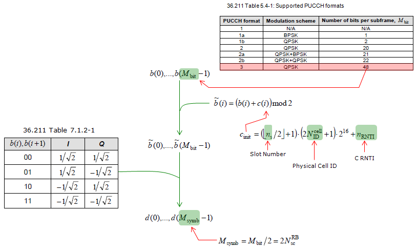
Step 1. 48 scrambled bits become 24 QPSK symbols, which is 2 x 12, one set of 12 for each slot.
Msymb = Mbit/2 = 2NscRB = 24 : the note at the bottom fixes the symbol count to two RBs worth of subcarriers.The same cinit as format 2 : cinit = (floor(ns/2) + 1) x (2NIDcell + 1) x 216 + nRNTI, restarted in every subframe.d(0) to d(11) belong to slot 0 : d(12) to d(23) belong to slot 1. Step 2 shows where this split happens.QPSK only : 36.211 Table 7.1.2-1 on the left maps each bit pair to +/-1/√2 on both axes.
PUCCH Format 3 Signal Generation - Spread Symbols y
Step 2 : Generation of y( ) This is the block spreading. In the diagram below, each set of 12 symbols is copied onto every data SC-FDMA symbol of its slot. Each copy is weighted by one element of an orthogonal sequence w from 36.211 Table 5.4.2A-1, at the bottom. A phase factor from ncscell(ns, l) rotates each copy as well.
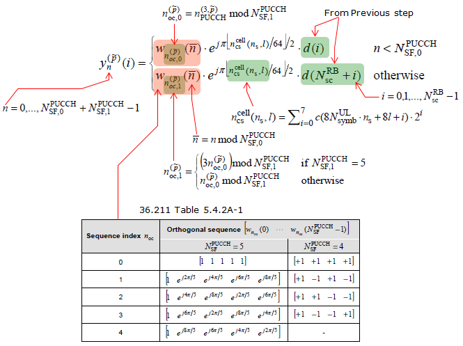
Step 2. Block spreading. Slot 0 repeats d(0) to d(11) and slot 1 repeats d(12) to d(23), and the orthogonal sequence index noc separates the UEs.
n counts the data SC-FDMA symbols of the subframe : n = 0 to NSF,0PUCCH + NSF,1PUCCH - 1, which is 0 to 9 for normal format 3. The upper row applies while n < NSF,0PUCCH, so the first slot uses d(i).NSF,1PUCCH can be 4 : the shortened format 3 leaves the last symbol of the subframe free for SRS. The second slot then uses the length-4 sequences in the right column.The sequence index comes from the resource index : noc,0 = nPUCCH(3,p) mod NSF,1PUCCH. In the second slot, noc,1 = (3noc,0) mod NSF,1PUCCH when NSF,1PUCCH = 5.Table 5.4.2A-1 has two kinds of sequence : five DFT sequences of length 5 and four Walsh sequences of length 4. Index 4 has no length-4 sequence, so only four sequences are available when the subframe is shortened.The phase factor is cell specific : ncscell(ns, l) is an 8-bit pseudo-random value, so ejπfloor(ncscell/64)/2 is a multiple of π/2 that changes from symbol to symbol.
The equation below is the second half of Step 2. After the spreading, each 12-value block is cyclically shifted across its 12 subcarriers.

Step 2, continued. The shift is ncscell(ns, l) mod 12, so it changes with the slot and the SC-FDMA symbol.
The same shift for every UE in the cell : the shift depends only on cell-specific values, so the UEs of one RB pair stay orthogonal through w.
PUCCH Format 3 Signal Generation - Transform Precoding z
Step 3 : Generation of z( ) This is the transform precoding, which makes format 3 an SC-FDMA signal like PUSCH. The equation below takes a 12-point DFT of each shifted block. It also scales the result by 1/√P, where P is the number of antenna ports.
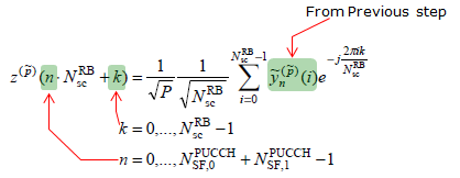
Step 3. One 12-point DFT per SC-FDMA symbol. The output z fills 12 subcarriers in each of the 10 data symbols of the subframe.
k is the subcarrier, n is the symbol : k = 0 to 11 and n = 0 to NSF,0PUCCH + NSF,1PUCCH - 1.1/√P splits the power : with two antenna ports, each port sends half the power.The DMRS are not in z : 36.211 clause 5.4.3 maps z to the RB of each slot and skips SC-FDMA symbols 1 and 5, which carry the DMRS (Table 5.5.2.2.2-1).
Put the steps together, and 48 bits become 24 QPSK symbols, 12 per slot. Each set of 12 is repeated over the data symbols of its slot, weighted by the UE's orthogonal sequence and rotated by a cell-specific phase. A cyclic shift and a 12-point DFT then turn each copy into one SC-FDMA symbol.
One RB pair, up to 5 UEs : the orthogonal sequence index keeps them apart.12 symbols per SC-FDMA symbol : this is why format 3 carries 48 bits while format 2 carries 20.SRS shortens only the second slot : NSF,1PUCCH drops to 4, and the length-4 Walsh sequences take over.
How does the UE know which PUCCH Format 3 resource to use?
The RB mapping needs nPUCCH(3,p), but RRC gives the UE up to four values, not one. The choice among them arrives in each downlink assignment. So the eNB can move the PUCCH from subframe to subframe without new RRC signalling.
36.213 clause 10.1.2.2.2 defines the FDD procedure. For a PDSCH on a secondary cell, the UE reads the TPC field of the DCI on that SCell PDCCH as a pointer. Table 10.1.2.2.2-1 maps '00', '01', '10' and '11' to the 1st, 2nd, 3rd and 4th value of the list. This use of the TPC field is often called the ARI, the ACK/NACK resource indicator. With EPDCCH, the HARQ-ACK resource offset field does the same job.
The TPC field of the PCell DCI keeps its normal job, which is PUCCH power control. The UE assumes the same pointer value in every SCell DCI of one subframe, and 36.213 states that assumption. 36.213 clause 10.1.3.2.2 applies the same table in TDD. There, the TPC field of a primary cell PDCCH with a DAI greater than 1 also acts as the pointer.
There is one fallback. When the UE receives PDSCH only on the primary cell, it does not use format 3. It sends the HARQ-ACK on format 1a or 1b, with the resource taken from the first CCE of the PDCCH, as a single-carrier UE does.
The list itself arrives in PUCCH-ConfigDedicated-v1020. The diagram in the RB mapping section shows the Rel-10 form, where format3-r10 held n3PUCCH-AN-List-r10 directly. In 36.331 v19.3.0, format3-r10 refers to PUCCH-Format3-Conf-r13, and the list field is n3PUCCH-AN-List-r13, now OPTIONAL. The listing below is the current text.
Following is based on
PUCCH-ConfigDedicated-v1020 ::=     SEQUENCE {
    pucch-Format-r10                    CHOICE {
        format3-r10                     PUCCH-Format3-Conf-r13,
        channelSelection-r10                SEQUENCE {
            n1PUCCH-AN-CS-r10                   CHOICE {
                release                             NULL,
                setup                               SEQUENCE {
                    n1PUCCH-AN-CS-List-r10              SEQUENCE (SIZE (1..2)) OF N1PUCCH-AN-CS-r10
                }
            }                                                               OPTIONAL    -- Need ON
        }
    }                                                                       OPTIONAL,   -- Need OR
    twoAntennaPortActivatedPUCCH-Format1a1b-r10     ENUMERATED {true}       OPTIONAL,   -- Need OR
    simultaneousPUCCH-PUSCH-r10                     ENUMERATED {true}       OPTIONAL,   -- Need OR
    n1PUCCH-AN-RepP1-r10                            INTEGER (0..2047)       OPTIONAL    -- Need OR
}

PUCCH-Format3-Conf-r13 ::=  SEQUENCE {
    n3PUCCH-AN-List-r13 SEQUENCE (SIZE (1..4)) OF INTEGER (0..549)  OPTIONAL,   -- Need ON
    twoAntennaPortActivatedPUCCH-Format3-r13        CHOICE {
        release                                         NULL,
        setup                                           SEQUENCE {
            n3PUCCH-AN-ListP1-r13   SEQUENCE (SIZE (1..4)) OF INTEGER (0..549)
        }
    }                                                               OPTIONAL    -- Need ON
}
twoAntennaPortActivatedPUCCH-Format3-r13 carries n3PUCCH-AN-ListP1-r13, the list for the second antenna port. So a UE with two PUCCH antenna ports gets two resource values from one pointer, one for each port. The other branch of pucch-Format-r10, channelSelection-r10, configures PUCCH format 1b with channel selection instead of format 3.
RRC configures up to four resources : n3PUCCH-AN-List-r13 holds 1 to 4 values of INTEGER (0..549).The SCell DCI picks one : its TPC field points at the 1st to 4th value through 36.213 Table 10.1.2.2.2-1.PCell-only scheduling falls back to format 1a or 1b : format 3 is used only when an SCell PDSCH needs acknowledging, in FDD.The Rel-10 field names in the diagram are out of date : the current release wraps the list in PUCCH-Format3-Conf-r13.
Reference
[1] 3GPP TS 36.211 v19.3.0 - clauses 5.4, 5.4.2A, 5.4.3 and 7.1.2, Table 5.5.2.2.2-1, PUCCH format 3 and mapping to physical resources
[2] 3GPP TS 36.212 v19.3.0 - clause 5.2.3.1, channel coding of HARQ-ACK on PUCCH format 3
[3] 3GPP TS 36.213 v19.4.0 - clauses 10.1.1, 10.1.2.2.2, 10.1.3.1 and 10.1.3.2.2, PUCCH format 3 HARQ-ACK procedures
[4] 3GPP TS 36.331 v19.3.0 - PUCCH-ConfigDedicated-v1020 and PUCCH-Format3-Conf-r13