PUCCH Format 1
As you see in PUCCH Format page, the function of PUCCH Format 1,1a,1b is just to deliver 1 or 2 or 4 bits data to eNodeB. But there are pretty complicated process and factors as described below.
- PUCCH Format 1,1a,1b Location
- How are the location of multiple PUCCHs from Multiple UE ?
- Effects of Parameters on PUCCH Format 1 location
- Signal Generation of PUCCH Format 1
- Get the Test Procedure and Log / Amarisoft TechAcademy
There are many topics in LTE (especially on PHY layer) which cannot be cleary explained without going through each parameters and equations shown in the specification. Physical resource allocation is one of these topics.
Physical resource allocation for PUCCH format 1, 1a, 1b is determined by the following process. Don't get panic, equation itself is all within high school math. Only our patience and persistance is required.
First get some outstanding big picture and try to figure out how the big picture is implemented by the following math process.
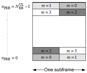
i) PUCCH is located around the extreme end of the system bandwidth in frequency domain. (Normally PUCCH Format 1 is located at a little less extreme edge, comparing with PUCCH format 2)
ii) The location of a PUCCH alternates between the two edges when slot number changes.
iii) Comparing to PUCCH format 2,2a,2b, Format 1 is using more variables to determine its location and most of these variables are set by higher layer message (SIB2,RRC Connection Setup, RRC Connection Reconfiguration etc)
I put the Excel spreadsheet to calculate the location here. (I haven't extensively tested my calculation. Let me know if you find any problem). Following equation is from 36.211 5.4.3 Mapping to physical resources.
< PUCCH Format 1 - PRB Mapping >
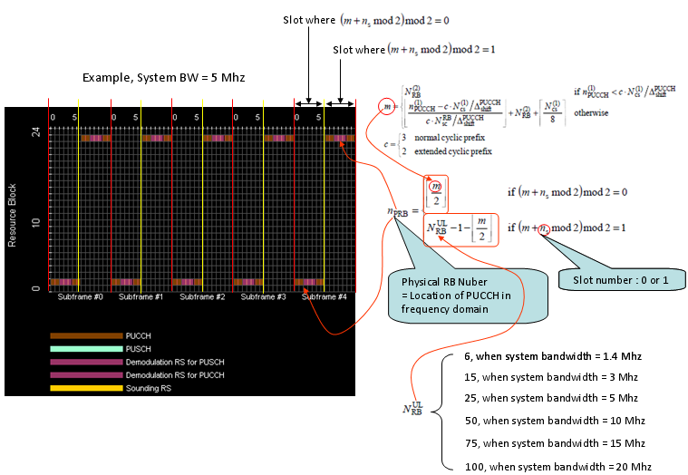
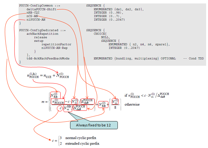
Most of the variables are specified by RRC message as shown below. Refer to following specs for the details.
- 36.211 5.4.3 Mapping to physical resources
- 36.213 10.1.2.1 FDD HARQ-ACK procedure for one configured serving cell
- 36.331 PUCCH-Config
< PUCCH Configuration - RRC Parameters >
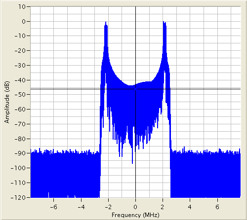
If you see a UL frame carrying a PUCCH (single PUCCH) only in frequency domain, it would look as follows.
< PUCCH Format 1 - Frequency Spectrum >
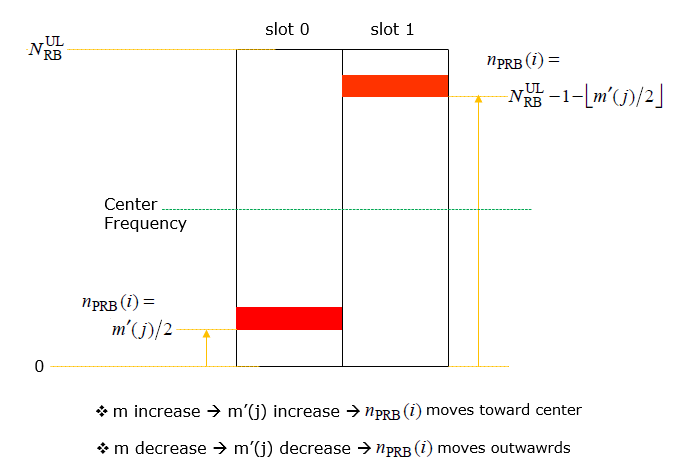
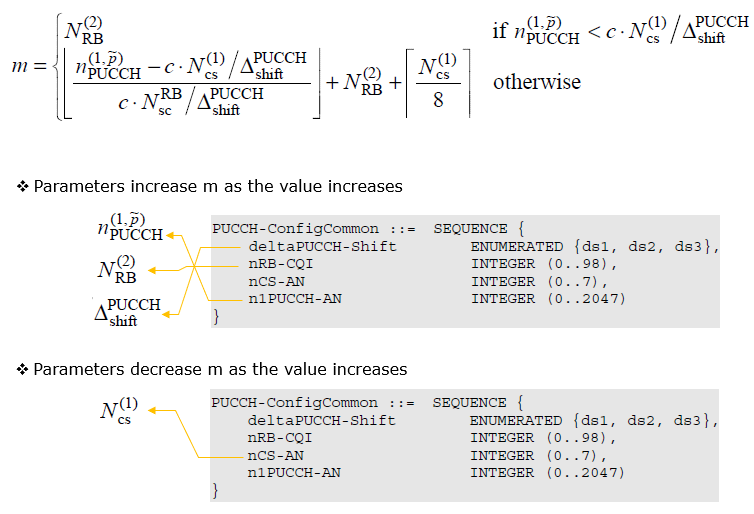
Effects of Parameters on PUCCH Format 1 location
Actually this is already explained in previous section in detail, but it may look too complicated and confusing. It is confusing to me as well. I need to spend quite a lot of time and energy everytime I look into this. So I tried to simplify the previous section in a little bit intuitive way as below.
My intuition can be summarized as three diagrams shown below. I don't think any further verbal explanation is necessary. I think (hope) the illustration itself is self explanatory.
< 36.211 - Figure 5.4.3-1: Mapping to physical resource blocks for PUCCH formats 1 – 3 for non-BL/CE UEs. >
NOTE : Regarding how each of these format are utilized and configured in signaling, check out this tutorial of Amarisoft TechAcademy.
Signal Generation of PUCCH Format 1
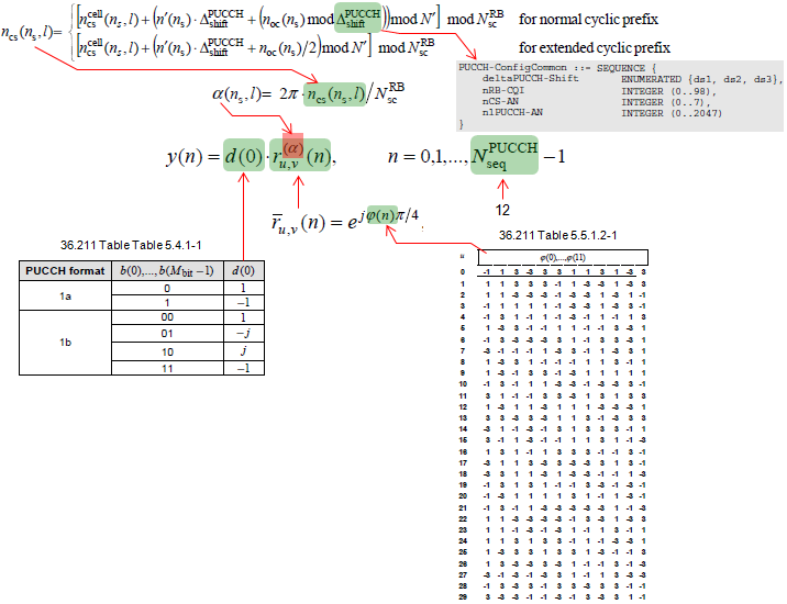
Step 1 : Generation of y(n). By this process, single complex number d(0) get converted to 12 complex numbers.
< PUCCH Format 1 Signal Generation - y(n) >
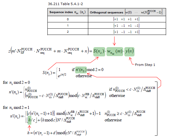
Step 2 : Generation of z(i). By this process and assuming N_SF = 4, 12 complex number y(n) get spreaded into 48 complex numbers.
< PUCCH Format 1 Signal Generation - y(n) >
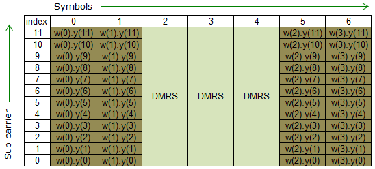
Step 3 : Mapping the data to each resource element
If we assume s(n_s) = 1, n_s = 1 (the first slot). The data (complex number) generated in previous step is allocated to each resouce elements in the PUCCH RB as follows.
< PUCCH Format 1 Signal Generation - RE Mapping >
How are the location of multiple PUCCHs from Multiple UE determined ?
The first question would be "Is it possible for multiple UEs to send PUCCH at the same subframe ?". Putting in another ways, "Is it possible for a eNB to receive multiple PUCCHs at the same subframe ?"
The answer is "It should be possible". (It should be possible since eNB can send multiple PDSCHs in the same subframe for multiple UEs).
Then the next question would be "Would the multiple PUCCHs from the multiple UE be multiplexed onto the same location (same PRB) or mapped to differenet/separate location ?"
We can think of roughly two mechanism for this. One is to multiplex multiple PUCCHs in the same location with using different orthogonal sequences. This mechanism allows the multiple PUCCH from multiple UE can occupy the same location.
On the contrary, there is a method that let PUCCH from different UEs be allocated in different location based on following logic.
< 36.213 10.1.2.1 FDD HARQ-ACK procedure for one configured serving cell >
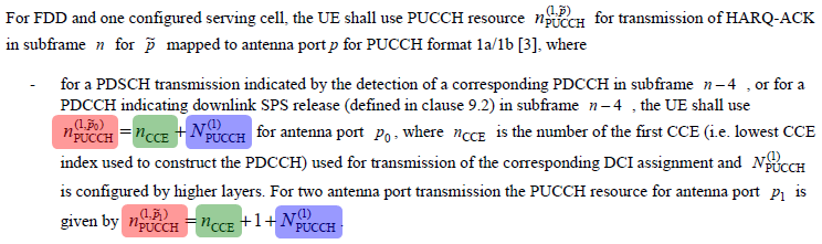
As you see the PRB calculation formula shown in the first section, the location of PUCCH format 1 changes by the parameter n1_PUCCH(marked in pink). and the n1_PUCCH is determined by n_CCE and N1_PUCCH. n_CCE here means the n_CCE for a specific DPCCH for a specific PDSCH.
Then the question would be "Which one of n_CCE and N1_PUCCH can be UE specific ?"
You can easily notice that N1_PUCCH cannot be a UE specific, since it is a common parameter (in SIB2) which implies that all the UE communicating to that specific eNB uses the same value.
Then n_CCE can be a UE specific ? There is no explcit answer to this, but you may be able to realize implcitely that this can be a UE specific. n_CCE here can indicate the location of a specific PDCCH for a specific PDSCH i.e UE specific PDSCH. (See CCE Index page). Therefore, you can say n1_PUCCH can be a UE specific and as a result PRB of PUCCH Format 1 (Location of PUCCH Format 1) can be a UE specific.