When I first tried creating WCDMA protocol test cases several years ago, I was struggled a lot due to the dependencies between different messages in RRC/NAS protocol sequences. But with LTE, I struggled even more. At least in WCDMA, UE send back explicit complaining message (e.g, Reject or Failure messages) but in LTE UE does not explicitely complain.. just stop doing anything and stay stucked there. So it is far more difficult to troubleshoot those issues in LTE if the root cause is from these message correlation.
If you are not the RRC/NAS protocol stack developer or test case developer, you would not see many of these issues on your daily life.. but once it happens, it is extremely difficult to find the root cause. One tip is to list up all the possible correlations and check through one-by-one until you are sure that there is no problem with these correlation issues.
The correlations in this page is not the full least and I will keep updating as I find more (as I come across more problems in my life -:))
A message correlation is a rule that ties an IE in one message to an IE in a later message. The later message may copy the value, answer it, or narrow it. This page lists the correlations of the LTE attach and tracking area update procedures, with the source and target of each IE.
Followings are the topics to be covered in this page.
- Correlation Overview
- EPS Attach Type and Attach Result
- UE Network Capability and Replayed UE Security Capabilities
- PDN Type and Access Point Name
- Old GUTI or IMSI and GUTI
- Reference
Correlation Overview
Which IEs of the attach and tracking area update procedures depend on each other? The two diagrams below give the overview before the tables go into the octets. Each box is a message, and each arrow runs from the IE that sets a value to the IE that must match or answer it.
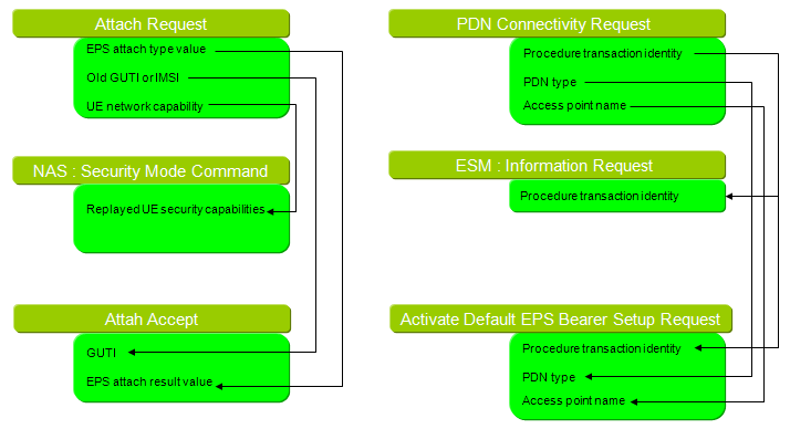
Correlations in the attach procedure. The EMM messages are on the left and the ESM messages on the right.
On the EMM side, the Attach Request feeds two later messages. Its UE network capability comes back in the Security Mode Command. Its EPS attach type value and Old GUTI or IMSI are answered in the Attach Accept. On the ESM side, the PDN Connectivity Request sets the procedure transaction identity. The ESM Information Request and the Activate Default EPS Bearer Context Request reuse it. The PDN type and the access point name are answered in the same Activate Default EPS Bearer Context Request. The diagram labels these messages "Attah Accept" and "Activate Default EPS Bearer Setup Request"; 24.301 names them ATTACH ACCEPT and ACTIVATE DEFAULT EPS BEARER CONTEXT REQUEST.
The ESM Information Request is sent only when the UE sets the ESM information transfer flag in the PDN Connectivity Request. The UE sets it when the APN or the protocol configuration options must go under ciphering, and so must wait until security is active. 24.301 v20.0.0 clause 6.6.1.2.2 requires the MME to copy the PTI of the PDN Connectivity Request into that message.
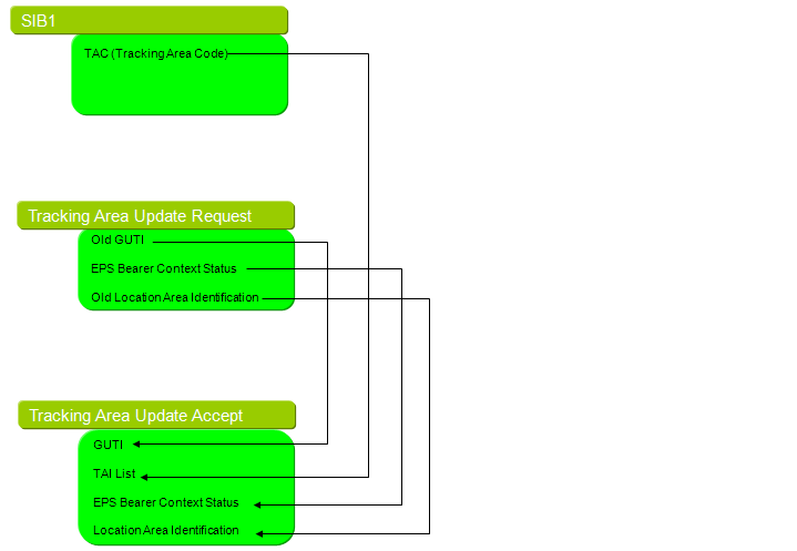
Correlations in the tracking area update procedure. The TAC comes from SIB1, and the other IEs come from the Tracking Area Update Request.
In the tracking area update, the TAC broadcast in SIB1 decides the tracking area the UE is in. The TAI List of the Tracking Area Update Accept then tells the UE where it can move without a new update. If the current TAI is not in that list, the UE starts another tracking area update. The EPS Bearer Context Status also has to match. When the UE includes it in the request, clause 5.5.3.2.4 requires the MME to answer with the bearers that are active on the network side. The MME deactivates locally every bearer that the UE reports as inactive.
Arrows run from the IE that sets a value : to the IE that must match or answer it.PTI of the PDN Connectivity Request : reused in the ESM Information Request and the default bearer activation.TAC in SIB1 : must fall inside the TAI List of the Tracking Area Update Accept.
EPS Attach Type and Attach Result
The first correlation is the simplest to check and one of the most common causes of a stuck attach. The UE states what kind of attach it wants, and the network answers with what it actually granted. The table below gives the two IEs.
|
EPS attach type value |
||
Source |
Message |
RRC Connection Setup Complete + EMM:Attach Request + PDN Connectivity Request |
IE |
Attach request.EPS attach type.EPS attach type value |
|
Target |
Message |
RRC Connection Reconfiguration + EMM: Attach Accept + Activate Default EPS Bearer Request |
IE |
Attach accept.EPS attach result.EPS attach result value |
|
24.301 v20.0.0 Table 9.9.3.11.1 defines five EPS attach type values. They are 1 for EPS attach, 2 for combined EPS/IMSI attach and 3 for EPS RLOS attach. Value 6 is EPS emergency attach, and 7 is disaster roaming attach. Table 9.9.3.10.1 allows only two EPS attach result values: 1 for EPS only, and 2 for combined EPS/IMSI attach.
A combined attach answered with EPS only is valid, but the Attach Accept must then carry an EMM cause, such as #2, #16, #17, #18 or #22. From that cause, clause 5.5.1.3.4.3 decides whether the UE retries the IMSI attach or treats CS fallback as unavailable. A test case that sends result 1 without a cause leaves the UE with no rule to follow. The opposite case, a result of combined attach for a request of EPS attach, grants more than the UE asked for.
EPS attach type value in the Attach Request : 1, 2, 3, 6 or 7.EPS attach result value in the Attach Accept : 1 for EPS only, 2 for combined.Combined request, EPS only result : needs an EMM cause in the Attach Accept.
UE Network Capability and Replayed UE Security Capabilities
The NAS Security Mode Command repeats the security capabilities of the UE back to it. The UE compares them with what it sent, which protects against a bidding-down attack on the first, unprotected Attach Request. The tables below give the octets that must match.
|
Length of UE network capability contents |
||
Source |
Message |
RRC Connection Setup Complete + EMM:Attach Request + PDN Connectivity Request |
IE |
Attach request.UE network capability.Octet1.Length of UE network capability contents |
|
Target |
Message |
dlInformationTransfer + EMM : Security Mode Command |
IE |
Security mode command.Replayed UE security capabilities.Octet1.Length of UE security capability contents |
|
|
EEA |
||
Source |
Message |
RRC Connection Setup Complete + EMM: Attach Request + PDN Connectivity Request |
IE |
Attach request.UE network capability.Octet2 |
|
Target |
Message |
dlInformationTransfer + EMM : Security Mode Command |
IE |
Security mode command.Replayed UE security capabilities.Octet2 |
|
|
EIA |
||
Source |
Message |
RRC Connection Setup Complete + EMM: Attach Request + PDN Connectivity Request |
IE |
Attach request.UE network capability.Octet3 |
|
Target |
Message |
dlInformationTransfer + EMM : Security Mode Command |
IE |
Security mode command.Replayed UE security capabilities.Octet3 |
|
|
UEA |
||
Source |
Message |
RRC Connection Setup Complete + EMM: Attach Request + PDN Connectivity Request |
IE |
Attach request.UE network capability.Octet4 |
|
Target |
Message |
dlInformationTransfer + EMM : Security Mode Command |
IE |
Security mode command.Replayed UE security capabilities.Octet4 |
|
|
UIA |
||
Source |
Message |
RRC Connection Setup Complete + EMM: Attach Request + PDN Connectivity Request |
IE |
Attach request.UE network capability.Octet5 |
|
Target |
Message |
dlInformationTransfer + EMM : Security Mode Command |
IE |
Security mode command.Replayed UE security capabilities.Octet5 |
|
The UE network capability is a mandatory LV IE in the Attach Request, so octet 1 is the length. Octets 2 to 5 carry the EEA, EIA, UEA and UIA algorithm bits. The Replayed UE security capabilities IE of the Security Mode Command is also a mandatory LV IE, with the same order for these four octets. The network must copy each algorithm octet exactly. The length matches only when the UE network capability stops at the UIA octet. 24.301 v20.0.0 clause 9.9.3.36 limits the replayed IE to 5 octets of contents, the last one for GEA, while the UE network capability can run to 13 octets. So a longer UE network capability is answered with a shorter replayed length, and that is not an error.
24.301 v20.0.0 clause 5.4.3.3 requires the UE to check that the replayed capabilities are unchanged. If they differ, clause 5.4.3.5 has the UE send SECURITY MODE REJECT with EMM cause #23, UE security capabilities mismatch. A test system can fail the attach here by shortening the replayed IE. Dropping the UEA and UIA octets of a UE with UTRAN support has the same effect. The NAS Security Mode Control page describes the whole procedure.
EEA, EIA, UEA and UIA octets copied exactly : octets 2 to 5 of both IEs.Length copied only for a short UE network capability : the replayed IE holds at most 5 octets of contents.Mismatch detected by the UE : SECURITY MODE REJECT with cause #23.
PDN Type and Access Point Name
The PDN connectivity request carries what the UE asks for, and the default bearer activation carries what the network grants. The PDN type and the APN can both differ between the two, but only in the ways that 24.301 allows.
|
PDN type value |
||
Source |
Message |
RRC Connection Setup Complete + EMM:Attach Request + ESM : PDN Connectivity Request |
IE |
PDN connectivity request.PDN type.PDN type value |
|
Target |
Message |
RRC Connection Reconfiguration + EMM: Attach Accept + ESM : Activate Default EPS Bearer Request |
IE |
Activate default EPS bearer context request.PDN address.Octet2.PDN type value |
|
|
APN1 |
||
Source |
Message |
RRC Connection Setup Complete + EMM:Attach Request + ESM : PDN Connectivity Request |
IE |
PDN connectivity request.Access point name |
|
Target |
Message |
RRC Connection Reconfiguration + EMM: Attach Accept + ESM : Activate Default EPS Bearer Request |
IE |
Activate default EPS bearer context request.Access point name.Octet2-Octet101.Access point name value |
|
|
APN2 |
||
Source |
Message |
ulInformationTransfer + ESM : PDN Connectivity Request |
IE |
PDN connectivity request.Access point name |
|
Target |
Message |
RRC Connection Reconfiguration + ESM : Activate Default EPS Bearer Request |
IE |
Activate default EPS bearer context request.Access point name.Octet2-Octet101.Access point name value |
|
Table 9.9.4.10.1 defines the PDN type values as 1 for IPv4, 2 for IPv6, 3 for IPv4v6, 5 for non IP and 6 for Ethernet. The UE may ask for IPv4v6 and get a single IP version. Clause 6.5.1.3 then requires an ESM cause in the Activate Default EPS Bearer Context Request. That cause is #50 PDN type IPv4 only allowed, #51 PDN type IPv6 only allowed, or #52 single address bearers only allowed. The PDN type value inside the PDN address IE must then match the address that is actually assigned.
The APN appears twice in the tables. APN1 is the attach case, where the PDN Connectivity Request travels inside the Attach Request. APN2 is an additional PDN connection, requested later in an ulInformationTransfer. In both cases the Activate Default EPS Bearer Context Request returns the APN of the connection. If the UE omitted the APN, the network selects the default APN, and the UE learns its name from that message. The APN page covers the APN format.
IPv4v6 narrowed to one version : needs ESM cause #50, #51 or #52.APN1 during attach, APN2 for an additional PDN : both answered in the default bearer activation.
Old GUTI or IMSI and GUTI
The UE identifies itself in the Attach Request with an old GUTI or with its IMSI, and the Attach Accept normally allocates a new GUTI. The two IEs share the EPS mobile identity format, so their octets line up as the table below shows.
|
GUTI or IMSI |
||
Source |
Message |
RRC Connection Setup Complete + EMM:Attach Request + ESM : PDN Connectivity Request |
IE |
i) Attach request.Old GUTI or IMSI.Octet1.Length of EPS mobile identity contents ii) Attach request.Old GUTI or IMSI.Octet2.Type of identity iii) Attach request.Old GUTI or IMSI.Octet3~Octet 12 |
|
Target |
Message |
RRC Connection Reconfiguration + EMM: Attach Accept + ESM : Activate Default EPS Bearer Request |
IE |
i) Attach accept.GUTI.Octet2.Length of EPS mobile identity contents ii) Attach accept.GUTI.Octet3.Type of identity iii) Attach accept.GUTI.Octet4~13 |
|
The octet numbers differ by one between the two messages. In the Attach Request, Old GUTI or IMSI is a mandatory LV IE, so octet 1 is the length. In the Attach Accept, the GUTI is an optional TLV IE with IEI 50, so octet 1 is the IEI and the length moves to octet 2. The type of identity field then tells the UE whether the value is a GUTI or an IMSI.
The Attach Request always travels in the RRC Connection Setup Complete, because it is the initial NAS message. The value of the new GUTI does not have to equal the old one. The correlation lies in the format, and in one rule. The UE stores the new GUTI and sends it as the old GUTI in its next Attach Request or Tracking Area Update Request. The GUTI arrow in the tracking area update diagram above follows the same rule.
Mandatory LV in the Attach Request, optional TLV in the Attach Accept : the octet numbers shift by one.New GUTI stored by the UE : used as the old GUTI in the next request.
Reference
[1] 3GPP TS 24.301 v20.0.0 - clauses 5.4.3, 5.5.1, 5.5.3, 6.5.1 and 6.6.1.2, and clause 9.9, NAS information elements