Simply put, the code rate can be defined as the ratio of the data rate that is allocated for a subframe and the maximum data rate that ideally can be allocated in the subframe. In other words, it means "The code rate is defined as the ratio between the transport block size and the total number of physical layer bits per subframe that are available for transmission of that transport block". A lower code rate means that more redundency bits are inserted during the channel coding process and a higher code rate means that less redundency bits are insterted.
- Is there any theoretical limit for Code Rate ?
- Example of Code Rate Calculation
- TTCN Code for Code Rate Calculation
- Code Rate vs MCS in LTE
Exact Calculation of Code Rate would be a little tricky and explaining the calculation method in writing may be even more tricky. If you are the type of person (like me) who can grasp the meaning from visualized from, refer to following illustration first and then try to read the rest of this page.
< Is there any theoretical limit for Code Rate ? >
I think this question would imply "Is there any theoretical Max Code Rate that would achive max throughput with minimum BER (or zero BER : Bit Error Rate) ?".
The relation between Code Rate and BER is a kind of statistical (probablistic) relation.. it is hard to find a clear cut value for this answer. When it comes to reality, the situation gets even more blurry since the performance of the reciever comes into play as well.
However, there is a guideline in 3GPP specification. TS36.213 7.1.7 Modulation order and transport block size determination and it says as follows.
The UE may skip decoding a transport block in an initial transmission if the effective channel code rate is higher than 0.930, where the effective channel code rate is defined as the number of downlink information bits (including CRC bits)divided by the number of physical channel bits on PDSCH. If the UE skips decoding, the physical layer indicates tohigher layer that the transport blockis not successfully decoded. For the special subframe configurations 0 and 5 withnormal CP or configurations 0 and 4 with extended CP, shown in table 4.2-1 of TS 36.211: “Evolved Universal Terrestrial Radio Access (E-UTRA); Physical channels andmodulation”, there shall be no PDSCH transmissionin DwPTS of the special subframe.
Based on this, I did some experiement with one of my reference device and eNB simulator. The test condition and the result is as follows.
- System BW = 15 Mhz
- Number of RB = 75
- MCS = 28
- DUT to Equipment Connection : Conductive and Downlink Power is high (meaning SNR is very good)
- Downlink 256 QAM : Disabled
- CFI vs Code Rate (Following is for the subframe with no PBCH)
|
CFI |
3 |
2 |
1 |
|
A |
55056 |
55056 |
55056 |
|
Number of Bits in PDSCH |
54000 |
59400 |
64800 |
|
Code Rate |
1.020 |
0.927 |
0.850 |
As you may guess, I got the best throughput with no CRC error with CFI = 1. I got pretty good throughput at CFI = 2 as well but I start see small portions of CRC error. If you don't decrease MCS at the subframe with PBCH, you would get much higher CRC error. We can say this result is pretty well aligned with the guideline described in 3GPP.
With CFI = 3, my reference device still tries to decode PDSCH even though Code Rate is very high (Based on my experience, all the Devices try to decode anyway however high code rate it is), but too high CRC error that leads to call drop.
< Example of Code Rate Calculation >
Let's take an example with MCS = 8 and No of RBs = 3.
For this we have to get the two numbers based on specification quoted above.
(i) number of downlink information bits (including CRC bits )
(ii) number of physical channel bits
(i) refers to "(Transport Block Size + CRC bits)" which is the size of the message that gets channel coded.
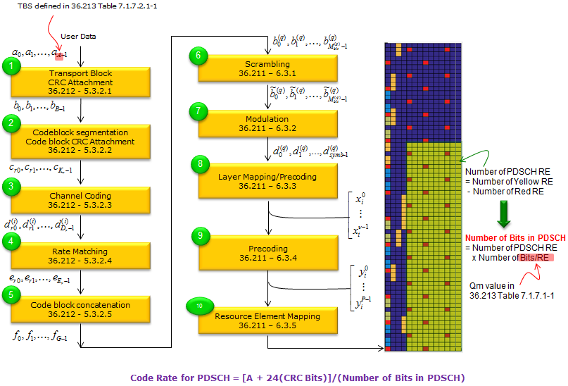
(ii) refers to the number of available bits in the PHYSICAL LAYER. Each resource element(RE) can carry 2, 4, or 6 bits depending on the modulation scheme.We just have to count the number of REs reserved for PDSCH transmission on each subframe, and then multiply it by 2, 4, or 6 (accordint to modulation scheme) and then we will have the number of physical channel bits on PDSCH.
Getting back to our example condition MCS = 8 and No of RBs = 3. In this case,
for item (i), we can easily figure this out from TS36.213 Table7.1.7.1-1
for item (ii) we have
a) 3 x 12 REs/symbol
b) (14 symbols/subframe) x (3 x 12 REs/symbols) = 504 REs/subframe. Out of this 504 REs, we have to remove those REs allocated for PDCCH since it is not carrying the real data. Let's assume that 3 symbols/subframe are allocated for PDCCH. In this case, the number of REs for avaiable in PHY LAYER for data transmission is 504 - (3 x (3 x 12)) which is 396. Now we have to convert this number into "number of bits". In our sample case, the modulation scheme is QPSK which carries 2 bits per RE. Therefore, the value for item (ii) is 2 x 396 = 792. This assumes that the subframe does not carry PBCH, PSS, SSS. If it is the subframe that carries these signals, we have to remove the REs for PBCH, PSS, SSS as well.
Now we have the value (i) and (ii). If you take (i)/(ii), you will get the Code Rate.
I admit the explanation above would sound too complicated and messy. I asked on this to another expert on this area and he gave me much clearer explanation as follows :
The code rate is the result (consequence) of the combination of TBS, MCS, and N_RB we have chosen for the transmission. Effective channel code rate is defined as the number of downlink information bits (including CRC bits) divided by the number of physical channel bits on PDSCH
Let us take the caseMCS=8; ITBS=8, TBS=808; N_PRB=6
The number of downlink information bits =808+24 (CRC bits) = 832. The number of physical channel bits on PDSCH = 6 (N_PRB)*12(no. of subcarriers in a PRB)*7(number of OFDM symbols in a slot)*2(no. of slots in a subframe)*2(number of bits per modulated symbols)=2016
Effective channel code rate = 832/2016 = 0.4127
< TTCN Code for Code Rate Calculation >
Still now clear ? Don't worry, you are not the only one who get confused. I am also one of them.
I just found a useful source clips from LTE Protcol Conformance TTCN (MAC_717.ttcn). For many engineers, one source code would worth 1000 words.
function fl_CalculateCodingRate ( integer p_I_MCS,
integer p_N_PRB,
integer p_TBSize) return boolean
{
const integer tsc_REs_Per_PRB := 138; /* @sic R5s100155 sic@
* 12 * 12 - 6 [Cell specific reference symbols] total 8, and 2 in symbols 0]
* with DCI =2, symbols o and 1 are used for REGs */
var integer v_BitsPerSymbol;
var float v_CodingRate;
// initialise v_BitsPerSymbol
if (p_I_MCS < 10)
{
v_BitsPerSymbol := 2 ; //QPSK
}
else if (p_I_MCS < 17)
{
v_BitsPerSymbol := 4 ; //16QAM
}
else if (p_I_MCS < 29)
{
v_BitsPerSymbol := 6 ; //64QAM
}
else
{
FatalError(__FILE__, __LINE__, "invalid imcs");
}
v_CodingRate := (int2float(p_TBSize + 24)) / (int2float(p_N_PRB * tsc_REs_Per_PRB * v_BitsPerSymbol));
if ( v_CodingRate <= 0.930)
{
return true; // TB size applicable
}
else
{
return false; // Coding rate is high hence TB size is not applied
}
} // end of f_CalculateCodingRate
As you see in the code above, the basic formula for code rate is
Code Rate = (Transport Block Size + Size of CRC Bits)/(Total number of REs x Number of Bits per Symbol)
The equation itself would look simple, but real calculation is not that simple mainly because it is hard figure out 'Total number of REs'. This 'RE (Resource Elements)' is the one that can carry PDSCH or PUSCH data. The REs carrying other bits (e.g, RS, PHICH, PDCCH, SRS etc) are not counted. Even though you allocated the same number of RBs and MCS, the number of REs within the allocated block would get different depending on various situation as follows :
i) Is it Uplink or Downlink (Frame Structure for UL/DL is different)
ii) How many symbols are allocated for control channel (PCFICH value) for Downlink ?
iii) What is transmission mode ? (Depending on Transmission mode, number of symbols for Reference Signal would vary)
iv) Does it carry SRS (Uplink) ?
etc
For more practical examples, refer to Reiver He's LTE Note : LTE FDD DL code rate calculation. You would see every detailed factors you need to consider if you want to calculate Code rate by hand.
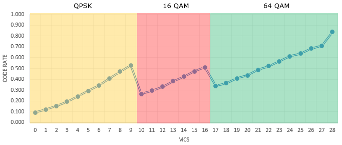
Followings are the code rate for each MCS in LTE assuming that the System Bandwidth is 20 Mhz and 100 RBs are allocated and 256 QAM is not supported. The exact code rate value would change a little bit, but the variation would be roughly within 1%.
|
MCS |
I_TBS |
Modulation |
TBS |
User Data |
Code Rate |
|
100 PRBs |
100 PRBs |
||||
|
0 |
0 |
QPSK |
2,792 |
30,000 |
0.094 |
|
1 |
1 |
QPSK |
3,624 |
30,000 |
0.122 |
|
2 |
2 |
QPSK |
4,584 |
30,000 |
0.154 |
|
3 |
3 |
QPSK |
5,736 |
30,000 |
0.192 |
|
4 |
4 |
QPSK |
7,224 |
30,000 |
0.242 |
|
5 |
5 |
QPSK |
8,761 |
30,000 |
0.293 |
|
6 |
6 |
QPSK |
10,296 |
30,000 |
0.344 |
|
7 |
7 |
QPSK |
12,216 |
30,000 |
0.408 |
|
8 |
8 |
QPSK |
14,112 |
30,000 |
0.471 |
|
9 |
9 |
QPSK |
15,840 |
30,000 |
0.529 |
|
10 |
9 |
16 QAM |
15,840 |
60,000 |
0.264 |
|
11 |
10 |
16 QAM |
17,658 |
60,000 |
0.295 |
|
12 |
11 |
16 QAM |
19,848 |
60,000 |
0.331 |
|
13 |
12 |
16 QAM |
22,920 |
60,000 |
0.382 |
|
14 |
13 |
16 QAM |
25,456 |
60,000 |
0.425 |
|
15 |
14 |
16 QAM |
28,336 |
60,000 |
0.473 |
|
16 |
15 |
16 QAM |
30,576 |
60,000 |
0.510 |
|
17 |
15 |
64QAM |
30,576 |
90,000 |
0.340 |
|
18 |
16 |
64QAM |
32,856 |
90,000 |
0.365 |
|
19 |
17 |
64QAM |
36,696 |
90,000 |
0.408 |
|
20 |
18 |
64QAM |
39,232 |
90,000 |
0.436 |
|
21 |
19 |
64QAM |
43,816 |
90,000 |
0.487 |
|
22 |
20 |
64QAM |
46,888 |
90,000 |
0.521 |
|
23 |
21 |
64QAM |
51,024 |
90,000 |
0.567 |
|
24 |
22 |
64QAM |
55,056 |
90,000 |
0.612 |
|
25 |
23 |
64QAM |
57,336 |
90,000 |
0.637 |
|
26 |
24 |
64QAM |
61,664 |
90,000 |
0.685 |
|
27 |
25 |
64QAM |
63,776 |
90,000 |
0.709 |
|
28 |
26 |
64QAM |
75,326 |
90,000 |
0.837 |
Following plot shows the relation between MCS and Code Rate based on the table show above.