|
Electronics |
||||
|
Transistors
What would be the most important electronic device in modern electronics ? What device would have the most widespread applications ? What device would be the most difficult to have clear understanding on ?
The answer would be a Transistor. At least to me, Transistor is the answer. Also at least to me, it is a component that I have the biggest struggle to understand. I have been wondering for many years on "Why it is so difficult for me ?". I think the reason would be that I haven't got anybody giving me simple/clear high level picture of the device. With no clear big picture, I've gone through a lot of documents showing infinite number of different amplifier circuits. It seems that I start understanding those circuits, but lose track in several days. Also I saw some materials explaining the physics of the transistor and its operation, but in most case they are above my brain capacity. Also I saw a lot of materials explaining on equivalent circuit models to mimic the operation of a transistor, but they would not stay long in my memory.
What I am trying to do in this page is to describe 'Transistor' in a very high level (20000 miles view) but can be very practical to understand its operation in various application. Here goes the topics I am going to talk about.
Let's start with what is a Transistor ? If you spend some time on googling, you may find several different versions on the origin of the name "Transistor". Among these, I think the one that sound the most relevant to the characteristics of a Transistor would be "Transistor is the combined word of 'Trans + resistor'". It means "Variable Resistor". Yes, Transistor is simply as variable resistor. If you have any experience with playing with electric circuits, you may have played with a variable reistor with a rotary nobe. so that you can change the resistance by rotating the nobe. The difference between the transistor and the rotary varible resistor is that we change the resistance with using electric current or voltage (control current, control voltage) as apposed to mechanical rotary to change the resistance. In most case, it is implemented in such a way that a small changes in control current/voltage would produce large ranges of variation in resistance value. This can be illustrated as shown below.
Do you think this is oversimplified ? Yes, it may be, but most of Transistor operation and application circuit can easily understood if you analyze it based on following two facts.
If you just type in the keyword 'Transistor application' in Google, you would have tons and tons of results and you may print out a thick book full of those application circuit. However, if you go through all of those circuits and try to find some common behavior, you would notice most of those circuits would fall into one of the following two : Amplifier or Switch.
Normally transistor is designed in such a way that a small changes in control current/voltage would cause large changes in resistance value and the large resistance variation will eventually cause large changes in output voltage/current. So if you compare the small input current/voltage and large output voltage/current, you can say the small control current/voltage is amplified.
If you think of this operation in terms of Voltage divider, it can be illustrated as below. I don't think you need any further explanation.
Even bigger application of transistor, especially in modern digital world, would be to use it as a switch. Not like those switches we flip back and forth with our fingers, but the one turned on/off by electric signal. Even in this case, the principle is same. We use the property of 'variable resistance' of a Transistor to implement the electric switch. Only a little difference comparing to 'Amplifier' case, we use or tune a transistor in a very specific way in which the resistance changes beween only two states : one is zero resistance and the other is infinite resistance.
A switch has two states : Open and Closed. Electrical representation of Open switch is 'Inifinite resistance' and the representation for Closed switch is 'Zero resistance'. So if we can make a transistor to act as 'Zero resistance' and 'Infinite resistance' with a control current/voltage as shown below, we can use it as a switch.
In high level view, all the logic gates (AND, OR, XOR, NAND) is implemented based on 'Switching capability of Transistor'. These gates are the basic building blocks of all the digital components. If we break it into one step further, transistors are the ultimate building block of all the digital components (from a simple logic gates to all the CPUs in every computers)
Why so much time and effort to study Transistor ?
Reading through what I described above, you may ask "If it is as simple as you said, why some many people/companies have been so much time/money on it for such a long time (several decades since the invention and the investment continues even now). And why we have to keep pulling hairs reading such a thick text books at school". I don't fully agree with the way they teach at school, but the research and investment made in industry has been contributing without any rest to the evolution of transistor. Even though great improvement has been achieved for fast several decades, the principle and fundamental use model still stay same. The improvement/evolution that has been made can be categorized into several branches as illustrated below. Main focus on the improvement has been on 'Smaller Size/Demension'. In many case, reducing the size/demension of a transistor tend to result in improvement in other aspects (e.g, Small Operating Voltage/Current, Faster Switching etc)
One data showing the evolution of transistor in terms of dimension is as follows. This is only for a little bit over past 10 years and coming 10 years. You would notice drastic decrease of the dimension. If you search a little more data showing the very early stage of transistor dimension, you would see even more drastic changes. What does this change (descrease in dimension) mean ? It means that you can put more transistors in a specific area (e.g, area within a CPU) implying higher processing power. Another general tendency with the decreased dimension would be 'faster switching' and 'lower operating voltage/current'. You may take this changes for granted because you have been seeing those improvement almost every year, but these changes are result of huge effort/investment in many fields (e.g, physics for theory and design, optics, chemistry, mechanics for manufacturing and electronics for testing etc).
I created a table showing the evoultion of transistor in terms of dimension as follows. The third colum is calculated by the second column (dimension) divided by the diameter of a Silicon Atom (110 picometer in radius ,220 picometer in diameter). If you use Van der Waals radius of Silicon Atom, the number in the third column would be around a half of the current value (210 picometer in radius, 420 picometer in diameter). The third colum is just to show you the rough idea of how small the device can be. It would not be exact value since there can be additional factors determining the number of items in the space.
The sources that I refered to create the table above are :
What kind of Transitors are out there ?
You may see or heard of so many different kind of transistors in the market, but most of them can fall into only one of two large categories. One of the categories is 'Junction' type and the other is 'FET (Field Effect Transistor)'. To understand the exact difference of these two types, you need to understand the underlying physics to make these device works. But I would not get into the detailed physics. I would just gives you some high level pictures.
Junction type transistor is usually controlled by the small current coming into the base (B) and mostly used for amplication purpose. FET type transistor is usually controlled by the small voltage applied on Gate-Source(Vgs) and mostly used for switching purpose and it become the basic building block of most digital devices.
You would find a good introduction to types of transistors at
How to characterize a Transistor ? : I-V Curve
One of the typical ways to characterize a transistor would be to construct and analyze the I-V curve (or Characteristic curve) that you might have seen in almost any electronics book. The graph may look simple, but it took me very long time to start understanding the real meaning of the curves. And I keep adding only small pieces one-by-one as I repeat the analysis. It never occurred to me for me to understand any new concept just by single look.)
The first step to understand any kind of graph is to understand the meaning of each axis. Each of axis in transistor I-V curve represent followings.
Just by brief look, you may think V_ce is an independent variable and I_c is a dependent variable for this curve, but in reality both V_ce and I_c are dependent variable. Then what is the independent variable ? The independent variable for this curve is Vcc. So the correct mathematical representation of the curve is a parametric fuction like f(Vcc) = [I_c(Vcc), V_ce(Vcc)]. Don't get panic on the math things.. you just repeat the following procedure and that is how you get this graph.
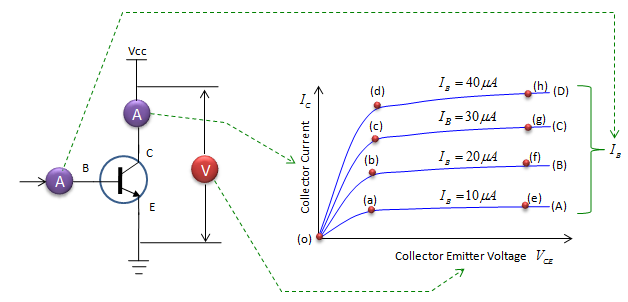
Taking the Graph (A) as an example, i) Fix the current flowing into Base to be 10 uA (Think of how you can provide this fixed current) ii) Set the Vcc to be 0 iii) Read Current Flowing into C (Ic) and Voltage across C-E (Vce) and put a point at (Ic,Vce) iv) Increment Vcc by a little bit (e.g, 0.1 V) v) Go to step iii)
Now let's take a specific curve and follow the meaning of the curve.
Let's take the curve (A). This shows how much current flows into collector (flow through the transistor) when we increment 'Collector Emitter Voltage' at the condition where the base current (current flowing into base) is 10 uA and the base current is maintained same over all the measurement period. Now let's split this curve into a couple of sectors and look at the characteristics of the sectors.
You would see the exactly same pattern in Curve (B), (C), (D) and you can interpret in the same way as you did for curve (A). Then what is the difference among the curve (A),(B),(C),(D) ? As you see, the difference is the slope of (o)-(a),(o)-(b),(o)-(c),(o)-(d). What the slope mean ? it means 'how much collector current changes when you change the collector emitter voltage ? Why we have this difference ? It is because the base current is different.
Now let's compare the point (a), (b), (c), (d). What kind of information you can get from the comparision ? As you see, the 'collector emitter voltage' at (a), (b), (c), (d) are all the same. Then what are differences ? The base current and collector current are different. From this, you can say "With a same collector emittor voltage, if you change the base current, the collector current also changes." For example, "With a same collector emittor voltage, if you increase the base current, the collector current also increase." This same rule applies to the whole region over the curve (A), (B), (C), (D).
|
||||