|
|
||
|
MIMO(Multiple Input Multiple Output)I think everybody would know what MIMO is. Simply put, it is a technique to increase the data throughput by using multiple transmitter antenna and multiple reciever antenna. Followings are topics that will be covered in this page.
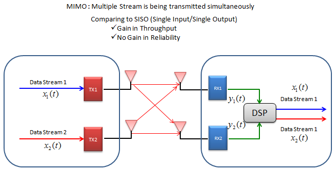
Basic.. Basic .. ConceptFollowing illustration is showing a very basic and over-simplified concept of MIMO. In very strict sense, it may be a little misleading but this can show the most common sense of MIMO concept. As you see in the illustration, with MIMO mutiple independent data streams are transmitted simulteneously and as a result it can achieve much higher data throughput in comparison to SISO (Single Input Single Output) case. However, there is almost no advantage in terms of reliability of data transfer (e.g, less error) comparing to SISO case.
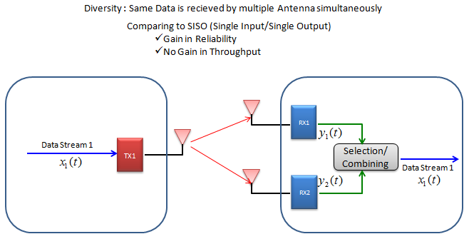
There is another concept which is often confused with MIMO. It is Diversity. What would be the difference between MIMO and Diversity ? Following illustration would show the concept of Diversity. There are basically two types of Diversity called Reciever Diversity and Transmitter Diversity. As you see in the illustration, in this Diversity configuration Single copy of one bit stream is being transmitted and reaches to multiple reciever antenna via a little different path, it means the reciever can have multiple versions of same data. Out of the multiple version, the reciever can select the best one or combine them all together in such a way to improve data quality. By doing this, communication reliability (less error) can be increased.. but no advantage in terms data throughput.
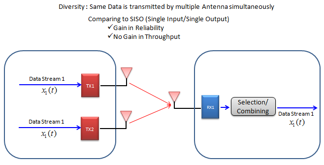
Here goes another type of Diversity. In this Diversity configuration, Multiple copies of one(single) bit stream is being transmitted via multiple Tx antenna and reaches to single reciever antenna via a little different path, it means the reciever can have multiple versions of same data. Out of the multiple version, the reciever can select the best one or combine them all together in such a way to improve data quality. By doing this, communication reliability (less error) can be increased.. but no advantage in terms data throughput.
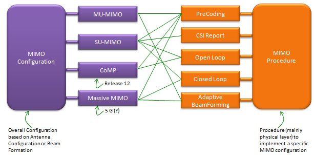
So.. overall concept is simple, but detailed process and implementation is not as simple as you may think. If you just want to get a common sense of MIMO. This would be enough. However, if you want to know very details of MIMO/Diversity especially about what's going on in physical layer, it would be almost impossible to understand the details of MIMO/Diversity concept without going through underlying mathmatics. Actually math itself is not that complicated but interpreting the math and translate the math into real implementation is difficult. I hope my math section in this site would helpful on this. (Please see the Engineering Math - Matrix as you go along this section). However describing and explain the full details of MIMO math would be huge task and it would take several month.. meaning this page will get updated for a while. Overall Configuration and ProcedureBefore jump into mathematical details, I want to summrize overall MIMO configurations that are most commonly accepted or discussed, and the PHY/MAC procedures that are used to implement each configuration. This is purely my personal classification. You may agree in terms of big picture, but may not agree in detailed level. The point is to show several keywords and key technologies related to MIMO. I don't think I can describe/explain all of these at mathematical level (at least in near future), I will be satisfied if I can successfully describe at least "SU-MIMO with Open Loop".
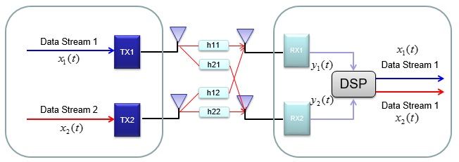
Mathematical Modeling of MIMOIn case of 2 x 2, overall data transmission process can be illustrated as follows. The red arrow and four blocks (h11,h12,h21,h22) between the two antenna is to illustrate the possible data path between the two Tx and two Rx antenna.
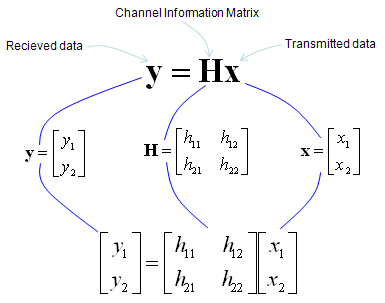
h11, h12,h21,h22 are special numbers (coefficient) to show how much of the data is going through each of the possible path. The greater the value is, the larger portions of data is being transmitted in that path. A matrix which is made up of these channel path coefficient is called "Channel Information Matrix". The reciever and transmitter relationship is represented as follows.
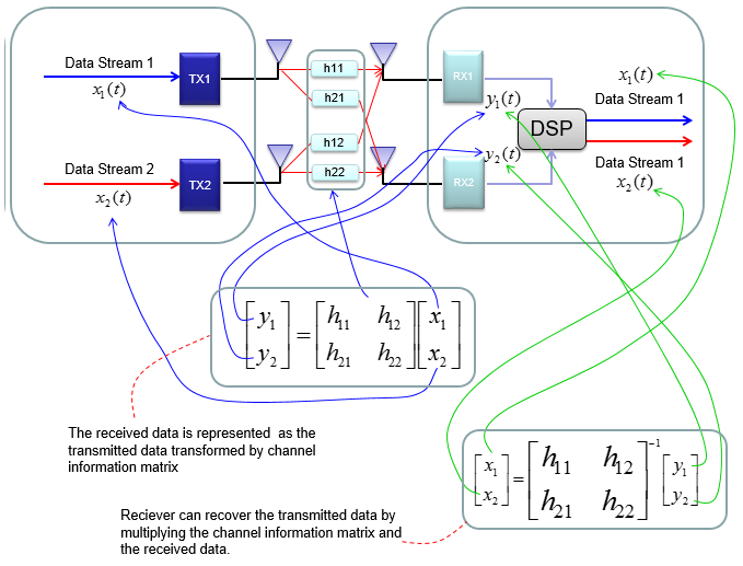
As I said the math itself is very simple. It would be like a first example at the first chapter of any linear algebra book. The important this is how to interpret this equation into real implementation. If I interpret it in an illustration, it would be as the path represented in green arrows. By this way, we can mathematically represent the recieved data (data distorted by the air path between transmitter and reciever antenna), but just calculating the recieved is not our goal (not the function of the reciever). Our goal is to extract/figure out the 'transmitted data (original data)'. Mathematically this is also simple and it is represented in green arrows.
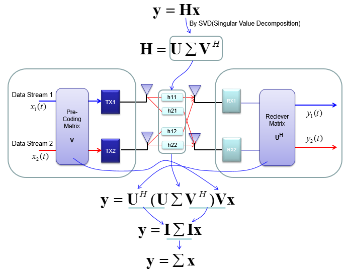
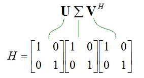
As you see in the process illustrated in green arrow, to recover the transmitted data (original data) from the received data we need to take inverse of the channel information matrix. Unfortunately there are a couple of issues with this method. i) Not all matrix is invertable. There are some matrix for which inverse matrix does not exists. (Please refer to here and see what kind of matrix is the one which is not invertable). ii) Calculating the inverse matrix is not the simple process. So if there is some way to preprocess the data in such a way that UE can decode the data without doing inverse matrix calculation of the channel matrix. To workaround these problems, we change the channel information matrix into three matrices by the method called SVD(Singular Value Decomposition). See the SVD page and clearly understand the meaning of this process. Probably my page would not be enough to give you full understanding about SVD. Google as much materials about this as possible and try to have some "Intuitive" understanding of the concept. When we apply any mathematical technique in engineering area, it should be meaningful in the engineering sense and should be implementable. The meaning and implementation of SVD can be illustrated as follows.
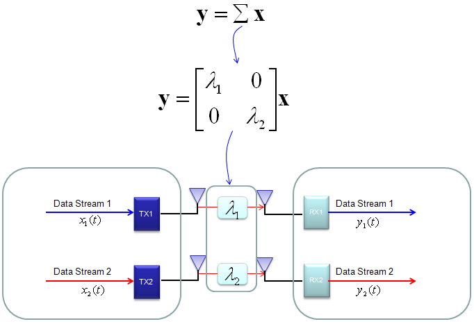
The important point is that by implementing this method, we can express the channel information matrix as a simple 'diagonal matrix'. That diagonal matrix is expressed as follows and can be illustrated as follows. Isn't it look simple and clear ? -:)
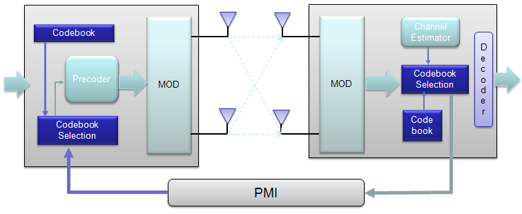
How the transmitter can figure out Precoding matrix ?In previous section, I roughly explained how to design(implement) Precoder. Simply put, take the channel matrix (H) and do SVD of the matrix and take the unitary matrix of the SVD result. Sound simple ? Maybe... Anyway let's assume that it sound simple and everybody understand this -:) However, in reality there is a critical issues that were not mentioned above. In previous section, the channel matrix H should be given to find Precoding matrix. Next question is, who (transmitter or reciever) can figure out H. It is the reciever because the reciever(UE in this case) can perform the channel estimation based on specific reference signal transmitted by the transmitter (eNB in this case). However, the precoding matrix is needed at transmitter(eNB). Then, how can the transmitter know of the precoding matrix ? Conceptually the simplest way would be that the reciever (UE) notify eNB of the whole precoding matrix. This is simple only in concept, but it is not simple to implement since it would require pretty big bandwidth to send the whole precoding matrix and this can be a huge overhead. To workaround this kind of overhead problem, 3GPP came up with a little bit of short cut as described below. In this method, they predefines a set of matrix based on the extensive investigation of the radio channel during the standardization process. These predefined matrix are known to both UE and eNB. And then UE select a specific precoder(precoding matrix) based on the its own channel estimation and informs eNB of the index of the precoding matrix that it selected. Since this is only the index of the matrix (not the matrix itself), we can implement this method without causing much overhead. For some MIMO implementation (e.g, TM4 in LTE = Closed Loop MIMO), you estimate the channel and select a specific precoding matrix and send it back to the receiver as shown below.
The algorithm by which UE select the codebook which is best fit for the channel at specific moment is as follows.
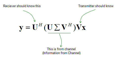
Once a specific codebook element (precoding matrix) is selected as shown here, that precoding matrix is used to transform the incoming bits as explained in Precoding section. Considerations for RealityNow you know about various aspect of MIMO channel model and conceptual mathematical representation. I hope it make sense to you at least in terms of mathematically. But as you know, when you try to implement the mathematical model into a real system, almost always you would meet something you haven't imagined when you are playing only in mathematical world. Let's look into folloing mathematical model again.
Can you guess what is known variable and what is unknown variable for each side (reciever and transmitter side) ? We can think of followings as a kind of known variables.
The issue is how to figure out the matrix V. About this matrix, there are two main problems.
One of the most common solution for this is that the reciever analyze channel matrix (H) and inform the transmitter of the best matrix V. This is called 'Closed loop MIMO' and LTE TM4 (Transmission Mode 4) belongs to this category. Now this kind of closed-loop method can solve all the problems listed above ? Unfortunately No. What are the problems now ? The problems that you can easily think of would be as follows :
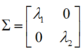
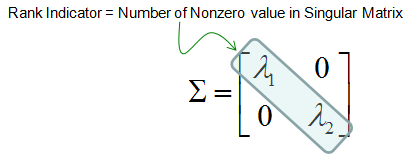
Rank IndicatorThe term Rank Indicator came from the pure mathematical term Rank Index. So, simply put, Rank Indicator is a special kind of UE measurement that reports Rank Index. Putting it in more practical aspect, Rank Indicator is a kind of number (indicator) that represents how well a MIMO communication works. For example, let's assume that a UE is communicating with a eNB with 2x2 MIMO configuration and UE reports RI(Rank Indicator) of '2', it implies that the 2x2 MIMO is performing as a real MIMO fashion. However, if UE reports RI of '1', it implies that the communication is going on as if it is with single antenna. It means that the 2x2 MIMO is not performing with the best efficiency. Explaining the same thing in a more formal way, it would go as follos : Let's remind us of the definition of Singular Matrix. It is defined as follows. It is a diagonal matrix. Once you get the singular matrix of a channel you can extract a couple of very important information from it.
One of the most important information you can get from the singular matrix is Rank Indicator. Rank Indicator is defined as Number of the diagonal elements which is not zero. Physical meaning of Rank Indicator is the number of independent communication channel. In case of 2 x 2 Singular matrix (for 2 x 2 MIMO) as an example, if the Rank Indictor is 2. Both diagonal elements as shown below is non-zero value and two separate communication pipe is established. If the Rank Indicator of the matrix is 1, one of the diagonal element (Lamda 1 or Lamda 2) is zero. It means even though we setup two antenna, the really working data stream is only 1, implying that the signal from one of the antenna is totally got lost or burried under noise which cannot be decoded.
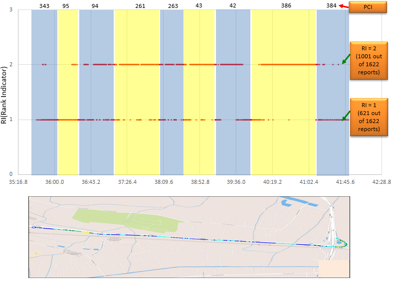
Following plot is from the data captured by a drive test tool Azenqos Drive Test tool (AZQ Android). I got the log captured by the tool and exported the data as csv file and then plot it on Microsoft Excel. The map displaying the path of the measurement shown at the bottom is the one automatically created by AZQ reporting tool. In this specific example, you would see a considerable amount of report with RI = 1, it implies that in many case 2x2 MIMO does not work with the full efficiency.
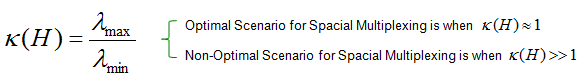
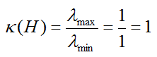
Condition NumberThen you might have question. Rank Indictor cares only on the number of non-zero values in the singular matrix. Does this mean that the amount of these number doesn't matter ? For example, isn't there any difference in terms of real communication performance between (lamda1 = 1, lamda2 = 1) and (lamda1 = 2, lamda2 = 0.1) ? In both case, Rank Indicator is same but real communication performance is different. So in order to properly estimate the real performance of MIMO channel we may need another indicator, that indicator is Condition Number as defined as below (according to reference [1]. I strongly recommend you to read this reference)
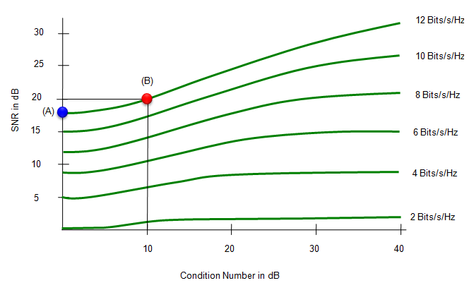
As stated above, as the difference among the diagonal numbers are less and less, the more optimal the MIMO channel works. Following graph from [1] shows this property. Horizonal axis indicates Condition Number in dB unit and Vertical Axis indicates the SNR in dB unit. Each line shows the case where the same amount of data rate is achieved. Each points on the line indicate 'To achieve a certain performance(data rate) at a certain condition number, how much SNR is required ?". or you can interpret it as "How much performance (data rate) you can get when you were given a certain condition number and a certain SNR". For example, let's look at the point labed (B). This point tells "In this specific communication system, when the condition number is 10 dB and SNR is 20 dB, we can achieve max 12 bits/s/Hz data rate". In order words, "to achieve 12 Bits/s/Hz data rate at the condition number 10 dB, we need at least 20 dB SNR". Now let's look at point (A). It tells "In this specific communication system, when the condition number is 0 dB and SNR is 16 dB, we can achieve max 12 bits/s/Hz data rate". In order words, "to achieve 12 Bits/s/Hz data rate at the condition number 0 dB, we need at least 16 dB SNR". What would you tell if you compare point (A) and point (B) ? At both points, we can achive the same performance (data rate), but at point (A) we could achieve the data rate even with poorer SNR comparing to point (B). In other words, as Condition Number get closer to 0 dB, we can achieve the data rate with poorer SNR. Try to pick some other places and describe the situation as I did until you get familiar with the interpretation of the graph and you will get the practical understanding of Condition Number.
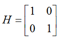
Now let's look into a couple of example of channel matrix and see how/what information we can get out of them. The example matrix itself comes from reference [1] and the tool that I used to perform SVD is reference [2] (Wolfram Alpha). First example goes as follows. Can you visualize the physical setup of transmitter and reciever from this matrix ? Since it is 2 x 2, you would have two transmitter antenna and two reciever antenna. It is 2 x 2 matrix. The elements except those on diagonal line are all zero. It means that there is no crosstalk between each antenna path. All the elements in the diagonal line are all '1'. It means 100% energy from transmitter antenna 1 is delivered to reciever antenna 1 without any loss and 100% energy from transmitter antenna 2 is delivered to reciever antenna 2 without any loss. Of course, you would never have this kind of condition in real wireless communication. But you can have this kind of condition when you do a lab test connecting 2 DUD antenna to 2 communication port on a test equipment.
Now let's do SVD to get Singular Matrix. Using Wolfram Alpha, I got the following result.
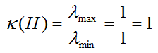
Now let's extract some information from the singular matrix. First.. what is Rank Indicator value ? It is 2 since the number of Non-zero elements on diagonal line is 2. Then let's take the condition number. It is '1' as shown below. It means it is perfect condition for spatial multiplexing and you should have maximum performance from this channel.
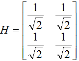
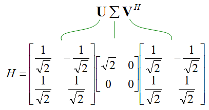
Second example goes as follows. Can you visualize the physical setup of transmitter and reciever from this matrix ? Since it is 2 x 2, you would have two transmitter antenna and two reciever antenna. It is 2 x 2 matrix. All the elements even non-diagonal elements are none zero. It means that there is crosstalk in all the possible ways. All the elements in the matrix are are same value which is 1/sqrt(2). It means 50% energy from transmitter antenna 1 is delivered to reciever antenna 1 and another 50% energy from transmitter antenna 1 is delivered to reciever antenna 2. and it also means 50% energy from transmitter antenna 2 is delivered to reciever antenna 1 and another 50% energy from transmitter antenna 2 is delivered to reciever antenna 2.
Now let's do SVD to get Singular Matrix. Using Wolfram Alpha, I got the following result.
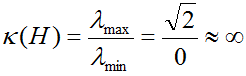
Now let's extract some information from the singular matrix. First.. what is Rank Indicator value ? It is 1 since the number of Non-zero elements on diagonal line is only 1. Then let's take the condition number. In pure mathematical sense, it cannot be calculated since the denominator is zero. But in practical sense, you can think of '0' as a very small number. In that case, you can get the condition number as shown below which is very large number. It means this channel is the worst condition for MIMO.
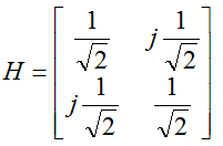
Third example goes as follows. Can you visualize the physical setup of transmitter and reciever from this matrix ? Since it is 2 x 2, you would have two transmitter antenna and two reciever antenna. It is 2 x 2 matrix. All the elements even non-diagonal elements are none zero. It means that there is crosstalk in all the possible ways, but the value between diagonal element and non-diagonal elements has 90 degree phase shift. It means 50% energy from transmitter antenna 1 is delivered to reciever antenna 1 and another 50% energy from transmitter antenna 1 is delivered to reciever antenna 2 with 90 degree phase shift. and it also means 50% energy from transmitter antenna 2 is delivered to reciever antenna 1 with 90 degree phase shift and another 50% energy from transmitter antenna 2 is delivered to reciever antenna 2. It means two signals transmitted from two transmitter antenna and comming into one reciever antenna does not interfere at all.
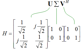
Now let's do SVD to get Singular Matrix. Using Wolfram Alpha, I got the following result.
Now let's extract some information from the singular matrix. First.. what is Rank Indicator value ? It is 2 since the number of Non-zero elements on diagonal line is 2. Then let's take the condition number. It is calculated to be 1 which means the perfect condition for MIMO. As you see here, even though there is cross talk between two communication path. It can be a very good condition for MIMO depending on the characteristics of the crosstalk. Would there be any way to implement this kind of channel condition ? Yes.. there is. If you cross polarize the antenna,you can have this kind of channel condition.
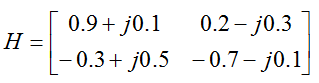
Here goes another example which can be more realistic. Can you visualize the physical setup of transmitter and reciever from this matrix ? Since it is 2 x 2, you would have two transmitter antenna and two reciever antenna. It is 2 x 2 matrix. All the elements even non-diagonal elements are none zero. It means that there is crosstalk in all the possible ways, but it is not easy to intuitively know exactly how much engergy goes to which antenna. Of course you can calculate this by taking the magnitue and angle of all of these complex numbers.. but let's just think of intuitive meaning. Since the magnitude and angle of all the elements are not the same, the crosstalk between the communication paths would not go 100% destructive way.
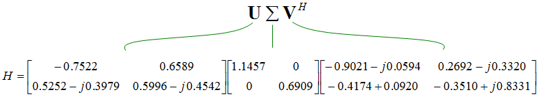
In this kind of situation, SVD can play important role. I got the result as below using Wolfram Alpha.
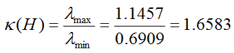
Now let's extract some information from the singular matrix. First.. what is Rank Indicator value ? It is 2 since the number of Non-zero elements on diagonal line is 2. Then let's take the condition number. It is calculated to be 1.6563 which is not the best case for MIMO and not the worst case either. It is less than 3 in dB unit. If you plug this number into the graph you saw above, it is pretty good condition for MIMO.
How UE and Network can figure out MIMO capability of each other ?In early stage of LTE deployment, most of UE supported only Category 3 or 4. In this case it is assumed that both Network and UE can support up to only 2x2 MIMO. However, recently (as of Jul 2017) we see the UEs and Networks supporting more than 2 antenna and all of the following MIMO configurations are becoming a common capability.
With these many options, Network need to know of the exact UE capability of Antenna configuration. Technically UE does not need to know about the network capability because UE is supposed to use whatever the network ask for, it is up to Network to figure out UE capability and configure the MIMO configuration not to exceed UE capability. However, there is way by which a UE can figure out Network (eNB) antenna configuration as well. How a UE can figure out the MIMO Capability of eNB : UE can figure out how many antenna eNB is using by checking PBCH CRC Mask. However, UE can figure out only the number of Antenna that eNB is using, it cannot figure out whether the Network can use all those antenna in MIMO or the Network use them in diversity purpose until it reaches RRC Connection Setup or RRC Connection Reconfiguration. How a NW can figure out the MIMO Capability of UE : Network can figure out the MIMO capability of UE via UE Capability Information message. Actually UE Capability Information does not carry any explicit information of UE MIMO capability. However Network can figure out UE MIMO capability indirectly from UE Category reported in UE Capability Information message. In UE Category table, you can figure out the number of layers that can be supported. From this information, the Network can indirectly figure out UE MIMO capability. For example, if the UE category says the UE category support the number of layer 2, it implies that the UE would support 2x2 or 4x2. If the UE category says the UE category support the number of layer 4, it implies that the UE would support 4x4 | | +-antennaInfo ::= CHOICE [explicitValue] OPTIONAL:Exist | | | +-explicitValue ::= SEQUENCE [1] | | | +-transmissionMode ::= ENUMERATED [tm3] | | | +-codebookSubsetRestriction ::= CHOICE [n2TxAntenna-tm4] OPTIONAL:Exist | | | | +-n2TxAntenna-tm3 ::= BIT STRING SIZE(2) [111111
| | +-antennaInfo ::= CHOICE [explicitValue] OPTIONAL:Exist | | | +-explicitValue ::= SEQUENCE [1] | | | +-transmissionMode ::= ENUMERATED [tm4] | | | +-codebookSubsetRestriction ::= CHOICE [n2TxAntenna-tm4] OPTIONAL:Exist | | | | +-n2TxAntenna-tm4 ::= BIT STRING SIZE(2) [111111
| | +-antennaInfo ::= CHOICE [explicitValue] OPTIONAL:Exist | | | +-explicitValue ::= SEQUENCE [1] | | | +-transmissionMode ::= ENUMERATED [tm3] | | | +-codebookSubsetRestriction ::= CHOICE [n4TxAntenna-tm4] OPTIONAL:Exist | | | | +-n4TxAntenna-tm3 ::= BIT STRING SIZE(64) [1111111111111111111111111111111111111111111111111111111111111111]
| | +-antennaInfo ::= CHOICE [explicitValue] OPTIONAL:Exist | | | +-explicitValue ::= SEQUENCE [1] | | | +-transmissionMode ::= ENUMERATED [tm3] | | | +-codebookSubsetRestriction ::= CHOICE [n4TxAntenna-tm4] OPTIONAL:Exist | | | | +-n4TxAntenna-tm3 ::= BIT STRING SIZE(64) [1111111111111111111111111111111111111111111111111111111111111111]
+-nonCriticalExtension ::= SEQUENCE [10] OPTIONAL:Exist +-lateNonCriticalExtension ::= OCTET STRING CONSTRAINTED [0000000101101010] OPTIONAL:Exist | +-RRCConnectionReconfiguration-v8m0-IEs ::= SEQUENCE [01] | +-lateNonCriticalExtension ::= OCTET STRING OPTIONAL:Omit | +-nonCriticalExtension ::= SEQUENCE [10] OPTIONAL:Exist | +-antennaInfoDedicatedPCell-v10i0 ::= SEQUENCE [1] OPTIONAL:Exist | | +-maxLayersMIMO-r10 ::= ENUMERATED [fourLayers] OPTIONAL:Exist | +-nonCriticalExtension ::= SEQUENCE OPTIONAL:Omit Reference
|
||