DCI
The function of DCI in 5G Trial is exactly same as LTE DCI, but items carried by the DCI is quite different from LTE DCI.
If you are completely new to LTE and not familiar with the DCI, I would recommend you to read at least the first page of the LTE DCI page.
In 5G Trial specification, only 4 different types of DCI are defined. Two for Downlink and Two for Uplink as listed below.
DCI Format A1 is used to schedule xPUSCH. It can be formatted in several different ways as shown below.
|
Field |
# of bits |
Value |
Description |
|
DCI Format Descriminator |
2 |
|
00 - Format A1 |
|
xPUSCH Range |
2 |
|
< 213 - 9.2 > 00 : the stopping of xPUSCH is the 12th symbol 01 : the stopping of xPUSCH is the 13th symbol 10 : the stopping of xPUSCH is the final (14th) symbol 11 : Reserved |
|
Transmission Timing of xPUSCH |
3 |
000(Bin) |
indicate 'l' = {0,1,2,3,4,5,6,7} |
|
RB Assignment |
9 |
325(Dec) |
|
|
Reserved |
9 |
|
|
|
CSI/BSI/BRI request |
3 |
|
000 - none of CSI/BSI/BRI is requested 001 - BSR reporting is required 010 - allocate BRRS and BRI reporting is required 011 - allocate BRRS but BRI reporting is not required 100 - allocate CSI-RS and CSI reporting is required 101,110,111 - reserved |
|
Transmission timing of CSI-RS / BRRS |
2 |
|
This field indicate 'm' in following equation CSI-RS / BRRS Transmission Timing = n + m ,where n = current subframe m = {0,1,2,3} |
| Indication of OFDM symbol index for CSI-RS / BRRS allocation |
2 |
|
If this DCI allocate CSI-RS, 00 - 13th symbol 01 - 14th symbol 10 - 13th & 14th symbol 11 - Reserved If this DCI allocate BRRS and higher layer gives 1 or 2 symbol BRRS configuration, 00 - 13th symbol 01 - 14th symbol 10 - 13th & 14th symbol 11 - Reserved If this DCI allocate BRRS and higher layer gives 5 or 10 symbol BRRS configuration, 00 - 5 symbols in slot 0 01 - 5 symbols in slot 1 10 - 10 symbols 11 - Reserved |
| Process Indicator / Number of BSI Request |
2 |
|
If this DCI allocates either of CSI-RS or BRRS, this field indicates 'Process Indicator' as follows : 00 - Process #0 01 - Process #1 10 - Process #2 11 - Process #3 If this DCI triggers BSI report, this field indicates 'Number of BSI reportsr' as follows : 00 - 1 BSI report 01 - 2 BSI report 10 - 4 BSI report 11 - Reserved |
| "UCI on xPUSCH w/o UL-SCH data" indicator |
1 |
|
If UCI report is NOT triggered, this field is invalid and shall be set to 0 If UCI report is triggered, 0 - allows multiplexing of UL-SCH and UCI 1 - only UCI on xPUSCH |
| Beam switch indication |
1 |
|
213 - 8.3.4 , 8.4.4 |
| SRS Request |
3 |
|
MSB 2 bits : The indication of SRS Configuration 00 - No SRS Request 01 - Config #0 10 - Config #1 11 - Config #2 If MSB 2 bits != 00 LSB 1 bit : indicate as follows 0 - SRS on 13th OFDM symbol 1 - SRS on 14th OFDM symbol If MSB 2 bits == 00 LSB 1 bit is invalid (should be set to 0) |
| Antenna Ports and Number of Layers |
3 |
|
< 212 - Table 5.3.3.1.1-1 > 0 - 1 Layer, Port 40 1 - 1 Layer, Port 41 2 - 1 Layer, Port 42 3 - 1 Layer, Port 43 4 - 2 Layers, ports {40, 41} 5 - 2 Layers, ports {42, 43} 6, 7 - Reserved |
| SCID |
1 |
|
Indicate which n_SCID is applied for both DMRS in subframe n and CSI-RS in subframe n+m 0 - n_SCID = 0 1 - n_SCID = 1 |
| Precoding Matrix Indicator |
3 |
|
211 - Table 5.4.4A.2-1 |
| TPC command for xPUSCH |
2 |
|
213 - Table 6.1.1.1 |
|
UL dual PCRS |
1 |
|
If Single Layer transmission is configured 0 - the scheduled xPUSCH uses a PCRS AP corresponding to a DM-RS AP 1 - the scheduled xPUSCH uses two PCRS AP(s) the first AP is corresponding to the allocated DMRS AP the second AP is the one whose REs are co-located in the same subcarrier with the first PCRS AP Else this field is invalid and should be set to 0 |
< More than Zero RB Allocation >
|
Field |
# of bits |
Value(bin) |
Description |
|
DCI Format Descriminator |
2 |
|
00 - Format A1 |
|
xPUSCH Range |
2 |
|
< 213 - 9.2 > 00 : the stopping of xPUSCH is the 12th symbol 01 : the stopping of xPUSCH is the 13th symbol 10 : the stopping of xPUSCH is the final (14th) symbol 11 : Reserved |
|
Transmission Timing of xPUSCH |
3 |
Not 000 |
indicate 'l' = {0,1,2,3,4,5,6,7} xPUSCH Timing (subframe) = n + 4 + l + m ,where n = subframe of DCI reception |
|
RB Assignment |
9 |
<=324(Dec) |
|
|
HARQ Process Number |
4 |
|
|
|
MCS |
4 |
|
|
|
NDI |
1 |
|
|
|
CSI/BSI/BRI request |
3 |
|
000 - none of CSI/BSI/BRI is requested 001 - BSR reporting is required 010 - allocate BRRS and BRI reporting is required 011 - allocate BRRS but BRI reporting is not required 100 - allocate CSI-RS and CSI reporting is required 101,110,111 - reserved |
|
Transmission timing of CSI-RS / BRRS |
2 |
|
This field indicate 'm' in following equation CSI-RS / BRRS Transmission Timing = n + m ,where n = current subframe m = {0,1,2,3} |
| Indication of OFDM symbol index for CSI-RS / BRRS allocation |
2 |
|
If this DCI allocate CSI-RS, 00 - 13th symbol 01 - 14th symbol 10 - 13th & 14th symbol 11 - Reserved If this DCI allocate BRRS and higher layer gives 1 or 2 symbol BRRS configuration, 00 - 13th symbol 01 - 14th symbol 10 - 13th & 14th symbol 11 - Reserved If this DCI allocate BRRS and higher layer gives 5 or 10 symbol BRRS configuration, 00 - 5 symbols in slot 0 01 - 5 symbols in slot 1 10 - 10 symbols 11 - Reserved |
| Process Indicator / Number of BSI Request |
2 |
|
If this DCI allocates either of CSI-RS or BRRS, this field indicates 'Process Indicator' as follows : 00 - Process #0 01 - Process #1 10 - Process #2 11 - Process #3 If this DCI triggers BSI report, this field indicates 'Number of BSI reportsr' as follows : 00 - 1 BSI report 01 - 2 BSI report 10 - 4 BSI report 11 - Reserved |
| "UCI on xPUSCH w/o UL-SCH data" indicator |
1 |
|
If UCI report is NOT triggered, this field is invalid and shall be set to 0 If UCI report is triggered, 0 - allows multiplexing of UL-SCH and UCI 1 - only UCI on xPUSCH |
| Beam switch indication |
1 |
|
213 - 8.3.4 , 8.4.4 |
| SRS Request |
3 |
|
MSB 2 bits : The indication of SRS Configuration 00 - No SRS Request 01 - Config #0 10 - Config #1 11 - Config #2 If MSB 2 bits != 00 LSB 1 bit : indicate as follows 0 - SRS on 13th OFDM symbol 1 - SRS on 14th OFDM symbol If MSB 2 bits == 00 LSB 1 bit is invalid (should be set to 0) |
| Antenna Ports and Number of Layers |
3 |
|
< 212 - Table 5.3.3.1.1-1 > 0 - 1 Layer, Port 40 1 - 1 Layer, Port 41 2 - 1 Layer, Port 42 3 - 1 Layer, Port 43 4 - 2 Layers, ports {40, 41} 5 - 2 Layers, ports {42, 43} 6, 7 - Reserved |
| SCID |
1 |
|
Indicate which n_SCID is applied for both DMRS in subframe n and CSI-RS in subframe n+m 0 - n_SCID = 0 1 - n_SCID = 1 |
| Precoding Matrix Indicator |
3 |
|
211 - Table 5.4.4A.2-1 |
| TPC command for xPUSCH |
2 |
|
213 - Table 6.1.1.1 |
|
UL dual PCRS |
1 |
|
If Single Layer transmission is configured 0 - the scheduled xPUSCH uses a PCRS AP corresponding to a DM-RS AP 1 - the scheduled xPUSCH uses two PCRS AP(s) the first AP is corresponding to the allocated DMRS AP the second AP is the one whose REs are co-located in the same subcarrier with the first PCRS AP Else this field is invalid and should be set to 0 |
|
Field |
# of bits |
Value(bin) |
Description |
|
DCI Format Descriminator |
2 |
|
00 - Format A1 |
|
xPUSCH Range |
2 |
|
< 213 - 9.2 > 00 : the stopping of xPUSCH is the 12th symbol 01 : the stopping of xPUSCH is the 13th symbol 10 : the stopping of xPUSCH is the final (14th) symbol 11 : Reserved |
|
Transmission Timing of xPUSCH |
3 |
Not 000 |
indicate 'l' = {0,1,2,3,4,5,6,7} xPUSCH Timing (subframe) = n + 4 + l + m ,where n = subframe of DCI reception |
|
RB Assignment |
9 |
326(Dec) |
|
|
Frequency Band Index(n_RACH) |
3 |
|
n_RACH = {0,1,2,3,4,5,6,7} in 211 - 5.7.2 |
|
OCC indicator (f') |
1 |
|
|
|
Cyclic Shift Indicator(v) |
2 |
|
|
|
Reserved |
3 |
000(Bin) |
|
|
CSI/BSI/BRI request |
3 |
|
000 - none of CSI/BSI/BRI is requested 001 - BSR reporting is required 010 - allocate BRRS and BRI reporting is required 011 - allocate BRRS but BRI reporting is not required 100 - allocate CSI-RS and CSI reporting is required 101,110,111 - reserved |
|
Transmission timing of CSI-RS / BRRS |
2 |
|
This field indicate 'm' in following equation CSI-RS / BRRS Transmission Timing = n + m ,where n = current subframe m = {0,1,2,3} |
| Indication of OFDM symbol index for CSI-RS / BRRS allocation |
2 |
|
If this DCI allocate CSI-RS, 00 - 13th symbol 01 - 14th symbol 10 - 13th & 14th symbol 11 - Reserved If this DCI allocate BRRS and higher layer gives 1 or 2 symbol BRRS configuration, 00 - 13th symbol 01 - 14th symbol 10 - 13th & 14th symbol 11 - Reserved If this DCI allocate BRRS and higher layer gives 5 or 10 symbol BRRS configuration, 00 - 5 symbols in slot 0 01 - 5 symbols in slot 1 10 - 10 symbols 11 - Reserved |
| Process Indicator / Number of BSI Request |
2 |
|
If this DCI allocates either of CSI-RS or BRRS, this field indicates 'Process Indicator' as follows : 00 - Process #0 01 - Process #1 10 - Process #2 11 - Process #3 If this DCI triggers BSI report, this field indicates 'Number of BSI reportsr' as follows : 00 - 1 BSI report 01 - 2 BSI report 10 - 4 BSI report 11 - Reserved |
| "UCI on xPUSCH w/o UL-SCH data" indicator |
1 |
|
If UCI report is NOT triggered, this field is invalid and shall be set to 0 If UCI report is triggered, 0 - allows multiplexing of UL-SCH and UCI 1 - only UCI on xPUSCH |
| Beam switch indication |
1 |
|
213 - 8.3.4 , 8.4.4 |
| SRS Request |
3 |
|
MSB 2 bits : The indication of SRS Configuration 00 - No SRS Request 01 - Config #0 10 - Config #1 11 - Config #2 If MSB 2 bits != 00 LSB 1 bit : indicate as follows 0 - SRS on 13th OFDM symbol 1 - SRS on 14th OFDM symbol If MSB 2 bits == 00 LSB 1 bit is invalid (should be set to 0) |
| Antenna Ports and Number of Layers |
3 |
|
< 212 - Table 5.3.3.1.1-1 > 0 - 1 Layer, Port 40 1 - 1 Layer, Port 41 2 - 1 Layer, Port 42 3 - 1 Layer, Port 43 4 - 2 Layers, ports {40, 41} 5 - 2 Layers, ports {42, 43} 6, 7 - Reserved |
| SCID |
1 |
|
Indicate which n_SCID is applied for both DMRS in subframe n and CSI-RS in subframe n+m 0 - n_SCID = 0 1 - n_SCID = 1 |
| Precoding Matrix Indicator |
3 |
|
211 - Table 5.4.4A.2-1 |
| TPC command for xPUSCH |
2 |
|
213 - Table 6.1.1.1 |
|
UL dual PCRS |
1 |
|
If Single Layer transmission is configured 0 - the scheduled xPUSCH uses a PCRS AP corresponding to a DM-RS AP 1 - the scheduled xPUSCH uses two PCRS AP(s) the first AP is corresponding to the allocated DMRS AP the second AP is the one whose REs are co-located in the same subcarrier with the first PCRS AP Else this field is invalid and should be set to 0 |
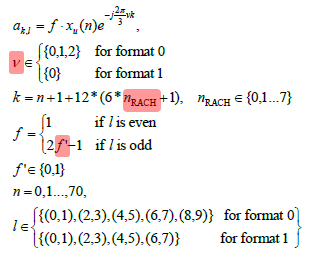
< 211 - 5.7.2 RACH RE Mapping >
DCI format A2 is also used for the scheduling of xPUSCH.
All of the information fields in the DCI format A1 are also used for DCI format A2 except the following field.
- DCI Format Descriminator = 01
DCI Format B1 is used to schedule xPDSCH. It can be formatted in several different ways as shown below.
|
Field |
# of bits |
Value |
Description |
|
DCI Format Descriminator |
2 |
|
00 - Format B1 |
|
xPDSCH Range |
2 |
|
< 213 - 8.1.4 > * MSB (starting of xPDSCH including DMRS symbol) : 0 is the second symbol, 1 is the third symbol * LSB (stopping of xPDSCH) : 0 is the 12th symbol, 1 is the 14th symbol. |
|
RB Assignment |
9 |
325(Dec) |
|
|
Reserved |
14 |
|
|
|
CSI/BSI/BRI request |
3 |
|
000 - none of CSI/BSI/BRI is requested 001 - BSR reporting is required 010 - allocate BRRS and BRI reporting is required 011 - allocate BRRS but BRI reporting is not required 100 - allocate CSI-RS and CSI reporting is required 101,110,111 - reserved |
|
Transmission timing of CSI-RS / BRRS |
2 |
|
This field indicate 'm' in following equation CSI-RS / BRRS Transmission Timing = n + m ,where n = current subframe m = {0,1,2,3} |
| Indication of OFDM symbol index for CSI-RS / BRRS allocation |
2 |
|
If this DCI allocate CSI-RS, 00 - 13th symbol 01 - 14th symbol 10 - 13th & 14th symbol 11 - Reserved If this DCI allocate BRRS and higher layer gives 1 or 2 symbol BRRS configuration, 00 - 13th symbol 01 - 14th symbol 10 - 13th & 14th symbol 11 - Reserved If this DCI allocate BRRS and higher layer gives 5 or 10 symbol BRRS configuration, 00 - 5 symbols in slot 0 01 - 5 symbols in slot 1 10 - 10 symbols 11 - Reserved |
| Process Indicator / Number of BSI Request |
2 |
|
If this DCI allocates either of CSI-RS or BRRS, this field indicates 'Process Indicator' as follows : 00 - Process #0 01 - Process #1 10 - Process #2 11 - Process #3 If this DCI triggers BSI report, this field indicates 'Number of BSI reportsr' as follows : 00 - 1 BSI report 01 - 2 BSI report 10 - 4 BSI report 11 - Reserved |
| Transmission timing of xPUCCH for UCI report |
3 |
|
This field is used only when DCI format any UCI report and this field indicate the transmission time offset value k = {0,1,2,3,4}. Otherwise, this field is reserved and be set to all zero |
| Frequency resource index of xPUCCH for UCI report |
4 |
|
This field is used only when DCI format any UCI report. Otherwise, this field is reserved and be set to all zero |
| Beam switch indication |
1 |
|
213 - 8.3.4 , 8.4.4 |
| SRS Request |
3 |
|
MSB 2 bits : The indication of SRS Configuration 00 - No SRS Request 01 - Config #0 10 - Config #1 11 - Config #2 If MSB 2 bits != 00 LSB 1 bit : indicate as follows 0 - SRS on 13th OFDM symbol 1 - SRS on 14th OFDM symbol in subframe n+4+m+k+1 If MSB 2 bits == 00 LSB 1 bit is invalid (should be set to 0) |
| Antenna Ports and Number of Layers |
4 |
|
< 212 - Table 5.3.3.1.3-1 > 0 - 1 Layer, port 8 (Ch. estimation w/o OCC) 1 - 1 Layer, port 9 (Ch. estimation w/o OCC) 2 - 1 Layer, port 10 (Ch. estimation w/o OCC) 3 - 1 Layer, port 11 (Ch. estimation w/o OCC) 4 - 2 Layers, ports {8, 9} (Ch. estimation w/o OCC) 5 - 2 Layers, ports {10, 11} (Ch. estimation w/o OCC) 6 - 2 Layers, ports {8, 12} (OCC=2) 7 - 2 Layers, ports {9, 13} (OCC=2) 8 - 2 Layers, ports {10, 14} (OCC=2) 9 - 2 Layers, ports {11, 15} (OCC=2) 10-15 |
| SCID |
1 |
|
Indicate which n_SCID is applied for both DMRS in subframe n and CSI-RS in subframe n+m 0 - n_SCID = 0 1 - n_SCID = 1 |
| TPC command for xPUSCH |
2 |
|
213 - Table 6.1.2 |
|
UL PCRS |
2 |
|
00 : {No PCRS} 01 : {PCRS on AP 60} 10 : {PCRS on AP 61} 11 : {PCRS on AP 60 and 61} |
< More than Zero RB Allocation >
|
Field |
# of bits |
Value(bin) |
Description |
|
DCI Format Descriminator |
2 |
|
00 - Format B1 |
|
xPUSCH Range |
2 |
|
< 213 - 9.2 > 00 : the stopping of xPUSCH is the 12th symbol 01 : the stopping of xPUSCH is the 13th symbol 10 : the stopping of xPUSCH is the final (14th) symbol 11 : Reserved |
|
RB Assignment |
9 |
<=324(Dec) |
|
|
HARQ Process Number |
4 |
|
|
|
MCS |
4 |
|
|
|
NDI |
1 |
|
|
| Redundancy Version |
2 |
|
|
| Bit-mapping index for HARQ-ACK multiplexing (BMI) |
3 |
|
< 213-8.5 > |
|
CSI/BSI/BRI request |
3 |
|
000 - none of CSI/BSI/BRI is requested 001 - BSR reporting is required 010 - allocate BRRS and BRI reporting is required 011 - allocate BRRS but BRI reporting is not required 100 - allocate CSI-RS and CSI reporting is required 101,110,111 - reserved |
|
Transmission timing of CSI-RS / BRRS |
2 |
|
This field indicate 'm' in following equation CSI-RS / BRRS Transmission Timing = n + m ,where n = current subframe m = {0,1,2,3} |
| Indication of OFDM symbol index for CSI-RS / BRRS allocation |
2 |
|
If this DCI allocate CSI-RS, 00 - 13th symbol 01 - 14th symbol 10 - 13th & 14th symbol 11 - Reserved If this DCI allocate BRRS and higher layer gives 1 or 2 symbol BRRS configuration, 00 - 13th symbol 01 - 14th symbol 10 - 13th & 14th symbol 11 - Reserved If this DCI allocate BRRS and higher layer gives 5 or 10 symbol BRRS configuration, 00 - 5 symbols in slot 0 01 - 5 symbols in slot 1 10 - 10 symbols 11 - Reserved |
| Process Indicator / Number of BSI Request |
2 |
|
If this DCI allocates either of CSI-RS or BRRS, this field indicates 'Process Indicator' as follows : 00 - Process #0 01 - Process #1 10 - Process #2 11 - Process #3 If this DCI triggers BSI report, this field indicates 'Number of BSI reportsr' as follows : 00 - 1 BSI report 01 - 2 BSI report 10 - 4 BSI report 11 - Reserved |
| Transmission timing of xPUCCH for UCI report |
3 |
|
This field is used only when DCI format any UCI report and this field indicate the transmission time offset value k = {0,1,2,3,4}. Otherwise, this field is reserved and be set to all zero |
| Frequency resource index of xPUCCH for UCI report |
4 |
|
This field is used only when DCI format any UCI report. Otherwise, this field is reserved and be set to all zero |
| Beam switch indication |
1 |
|
213 - 8.3.4 , 8.4.4 |
| SRS Request |
3 |
|
MSB 2 bits : The indication of SRS Configuration 00 - No SRS Request 01 - Config #0 10 - Config #1 11 - Config #2 If MSB 2 bits != 00 LSB 1 bit : indicate as follows 0 - SRS on 13th OFDM symbol 1 - SRS on 14th OFDM symbol in subframe n+4+m+k+1 If MSB 2 bits == 00 LSB 1 bit is invalid (should be set to 0) |
| Antenna Ports and Number of Layers |
4 |
|
< 212 - Table 5.3.3.1.3-1 > 0 - 1 Layer, port 8 (Ch. estimation w/o OCC) 1 - 1 Layer, port 9 (Ch. estimation w/o OCC) 2 - 1 Layer, port 10 (Ch. estimation w/o OCC) 3 - 1 Layer, port 11 (Ch. estimation w/o OCC) 4 - 2 Layers, ports {8, 9} (Ch. estimation w/o OCC) 5 - 2 Layers, ports {10, 11} (Ch. estimation w/o OCC) 6 - 2 Layers, ports {8, 12} (OCC=2) 7 - 2 Layers, ports {9, 13} (OCC=2) 8 - 2 Layers, ports {10, 14} (OCC=2) 9 - 2 Layers, ports {11, 15} (OCC=2) 10-15 |
| SCID |
1 |
|
Indicate which n_SCID is applied for both DMRS in subframe n and CSI-RS in subframe n+m 0 - n_SCID = 0 1 - n_SCID = 1 |
| TPC command for xPUSCH |
2 |
|
213 - Table 6.1.2 |
|
UL PCRS |
2 |
|
00 : {No PCRS} 01 : {PCRS on AP 60} 10 : {PCRS on AP 61} 11 : {PCRS on AP 60 and 61} |
DCI format B2 is also used for the scheduling of xPDSCH.
All of the information fields in the DCI format B2 are also used for DCI format A2 except the following field.
- DCI Format Descriminator = 01