I think the most steps in any wireless system (especially high end wireless system like Cellular communication system) is Synchronization. However, in terms of troubleshooting this step would be one of the trickest part. If you just take outside looking of the device or of Basestation, you would not get any clue on what got wrong in this step. Also, most of device (UE) log or Base station log, you would not see much detailed information about this step. You may only see 'Pass / Fail' print out in the log. Even when you find a specific log that print out some further details of this process, in most case those information would be printed out as a series of mysterious numbers. If you do not have the detailed understandings of the algorithm used for the synchronization process of the specific device, it would be almost impossible to interpret those information in the log. Usually this is the area of lower layer DSP engineer or FPGA engineer. However, it would be helpful if you have at least general understanding on how Synchronization process works and overall design concept of this process.
- NR Synchronization Process - Conclusion First !!!
- Overal Procedure of Synchronization and Initial Access
- How Synchronization work ?
- What kind of Information can be derived from the Synchronizaiton Signal ?
- Where to put and when to send ?
- Synchronization Signal in Frame Structure
NR Synchronization Process - Conclusion First !!!
For those who does not like long reading (including me -:), I would like to put the conclusion first. But I would suggest you to go through the whole page when you have some free time and try to get some big picture or principles of synchronization process in general in most of wireless communication.
When we say 'Synchronization' in communication technology, it usually mean 'synchronization for transmission' and 'synchronization for reception'.
In UE's point of view, 'transmitting direction' is called 'Uplink' and 'receiving direction' is called 'Downlink'. Applying this terms to synchronization process, we have two types of synchronization in cellular communication including 5G/NR called 'Downlink Synchronization' and 'Uplink Synchronization'.
Overal Procedure of Synchronization and Initial Access
Following is overall sequence of the Initial Access for most of cellular system with the focus on Synchronization process. Technically, step (1), (2), (3) can all be regarded as synchronization step. But when we just say "Synchronization", it usually mean Downlink Synchronization as indicated in step (1), (2). Of course, Uplink Synchronization is very important as well, but usually the uplink process (step (3)) is regarded as part of RACH process and normall treated under "RACH Procedure" or "Initial Access" process.
In this page, I would mostly handle on 'Downlink Synchronization' and I would treat Uplink Synchronization in another page dealing with RACH process / Initial Access.
When we design the synchronization signal and procedure, you have consider a lot of things into consideration. In NR(5G), there would be even longer list of factors you would have to consider in designing this procedure. I put down some of common factors being proposed in 3GPP technical discussions (TDocs) on this illustration, but there would be never ending list of factors you may add.

How Synchronization work ?
The most common way to implement the Synchronization is
i) Create a predefined signal (a predefined data sequence : This signal is called Sync signal)
ii) Put the signal into a specific OFDMA symbol in a specific subframe and transmit
Since UE already have (or can derive) all the details of the predefined sync signal, it can search and detect the data from the stream of data reaching the UE. Because the sync signal is located in the predefined location in time, UE can detect the exact timing from the decoded sync signal.
What kind of Information can be derived from the Synchronizaiton Signal ?
Most part of the answer to this question is obvious from the definition of 'Synchronization'. Roughly we can derive following informations from the synchronization signal. Item i) or ii) is obvious... but we can design the Synchronization signal in such a way that we can derive some additional information from it. For example, in LTE (as you see in LTE Physical Cell IDpage), we can derived Physical Cell ID from LTE Sync signal.
In NR (5G), it has been discussed on adding some additional information onto the sync signal.
i) Radio Frame Boundary (the location of the first symbol in a radio frame)
ii) Subframe Boundary (the location of the first symbol in a subframe)
iii) Some additional information (e.g, Physical Cell ID, Hypercell ID, System ID etc)
Now wiith the final decision on NR Sync signal specification , I don't see much of the additional information comparing to LTE sync signal. Even though the location and transmission period of the sync signal is pretty much different from LTE Sync signal, it looks almost same as LTE Sync signal in terms of the type of information we can derive from the sync signal. However, in NR Sync signal and PBCH signal is regarded as single block. If we consider PBCH as a part of sync signal, we can say NR sync signal carries more information as mentioned above.
Where to put and when to send ?
NOTE : NR Synchronization Signal transmission method is now determined and specified in 38.211 and what is described in this section would not be exactly same as NR Sync Signal Transmission. But I leave this section as it is, just to give you the general idea of various options of Sync signal transmission. If you are not interested in this kind of general description and jump directly into NR Synchronization, go to the section NR Syncrhonization Signal.
The questions is "At which subframe and at which OFDM symbol(s), the Sync signal will be placed". Several different idea / possibilities are proposed as shown below.
Descriptions will posted later (Try to make your own story out of this .. or refer to R1-166653 ([2])
|
|
In this proposal, Network put the synchronization signal in a special location in time and frequency domain in a predefined timing interval. This is the same idea that we use in current LTE. The advatange of this idea is that it is simple to implement and UE implementation for detecting synchronization can be simple. The disadvantage is that this is not flexible and we would not be able to remove this resources even when we have better idea for synchronization in the future. Also, Network is transmitting the sync signal all the time even when there is no UE around it. So it can be a waste of radio resource and energy. |
|
|
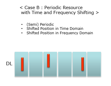
In this proposal, it is allowed that the location of synchnronization can be shifted in time and/or frquency domain within a certain window. The advantage is that it can have more flexibility comparing to the previous proposal. The disadvantage would be that UE sync signal detection process would get a little bit more complicated and it requires more complicated design. |
|
|
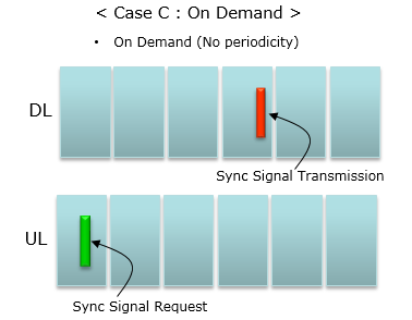
In this proposal, Network does not transmit the sync signal all the time. It transmit the sync signal only when it gets the transmission request from UE. Advantage of this proposal is that the location of sync signal can be very flexible and it can minimize the resource allocation and energy consumption for sync signal transmission because it transmit the signal only when it is really necessary. Disadvantage is that it would cause more energy consumption on UE side since UE has to send request signal to get the sync signal. Another disadvantage would be that Network should have much sophisticated Uplink signal detection process because it should be able to detect the Uplink signal that UE send without any timing reference.
|
|
|
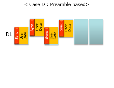
In this option, Network Transmit the synchronization signal at the beginning of each downlink frame as a preamble and UE aquire the synchronization from the preamble. This is similar concept that is used in WLAN. Advatange for this option would be similar to the advantage of On-Demand case. Disadvantage is that it would make UE design complicated and the sync signal overhead would increase because every downlink frame should reserve a certain amount of resources for synchoronization signal. |

Synchronization Signal in Frame Structure
NOTE : NR Synchronization Signal in Frame Structure is now determined and specified in 38.211 and what is described in this section would not be exactly same as NR Sync Signal locations within NR Frame. But I leave this section as it is, just to give you the general idea of various options of Sync signal transmission. If you are not interested in this kind of general description and jump directly into NR Synchronization, go to the section NR Syncrhonization Signal.
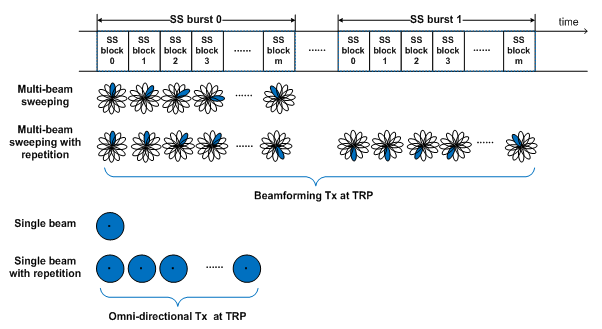
Since both Single Beam and Multibeam should be supported in 5G, there would be a little bit different strategy depending on whether it is for Single beam or Multi Beam. Within each beam management type, there can be different strategy depending on whether the network transmit the SS signal in repetitive maner or in single transmission. All of these patterns are well described in R1-1611272 as shown below.
A couple of questions that may help you to get more concrete understanding would be (Try to find answers to these questions when 3GPP specification is finalized. You may find answers to these questions even now in case of Pretrial specification)
- What is the unit of SS block ? Is it a OFDM symbol ? or a subframe ?
- What is the unit of SS burst ? Is it a subframe or multiple subframes ?
- What is the size of a SS burst ? (i.e, how many SS blocks in a SS burst) ?
- Are the data in each SS block all the same except Beam Pattern/Direction ?
- How the time gap between each SS burst is defined / configured ?
Reference
[1] 3GPP R1-166107. 3GPP TSG RAN WG1 Meeting #86 - Synchronization and initial access mechanism in NR
[2] 3GPP R1-166653. 3GPP TSG RAN WG1 Meeting #86 - Consideration on synchronization for NR
[3] 3GPP R1-166910. 3GPP TSG RAN WG1 Meeting #86 - LG_Discussion on DL Synchronization in NR v1.1_final
[4] 3GPP R1-166948. 3GPP TSG RAN WG1 Meeting #86 - Transmission of synchronization signal on demand
[5] 3GPP R1-166949. 3GPP TSG RAN WG1 Meeting #86 - Band agnostic synchronization and cell search
[6] 3GPP R1-167028. 3GPP TSG RAN WG1 Meeting #86 - Sync and Beam Acquisition Procedure in Multi-Beam Based Approach
[7] 3GPP R1-167672. 3GPP TSG RAN WG1 Meeting #86 -Synchronization in NR considering beam sweeping
[8] 3GPP R1-167705. 3GPP TSG RAN WG1 Meeting #86 - Design on NR DL Synchronization
[9] 3GPP R1-167707. 3GPP TSG RAN WG1 Meeting #86 - Initial performance evaluation of different beamforming options for NR synchronization signals
[10] 3GPP R1-1611272 3GPP TSG RAN WG1 Meeting #87 (RAN1-NR#1) - Overview of NR initial access
[11] 3GPP R1-1703422 3GPP TSG RAN WG1 Meeting #88 - On NR-SS structure and time indexing