The PBCH Transport Process encompasses a series of steps to prepare and transmit the Physical Broadcast Channel (PBCH) information. The PBCH is a key component in cellular communication networks, particularly in LTE and 5G systems. It serves as the primary channel through which a base station (eNodeB in LTE, gNodeB in 5G) transmits MIB to UEs.
The PBCH carries crucial information that a UE needs to decode other broadcast information and to establish a connection with the network.
- PBCH Transport Process
- (1) PBCH Payload Generation
- (2) Scrambling
- (3) CRC Attachment
- (4) Channel Coding
- (5) Rate Matching
- (6) Scrambling
- (7) Modulation
- (8) Resource Element Mapping
- RRC Parameters
- Reference
PBCH Transport Process
Following diagram illustrates the PBCH Transport Process in a cellular communication system, detailing the sequence of steps involved in preparing and transmitting the PBCH from gNB to UE
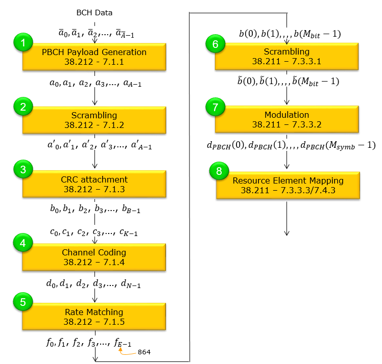
Followings are short descriptions of each of the steps illustrated above. I would not explain much in words for this process and I don't think I can make you understand the details of this process just by words. The purpose of following description (illustrations) is to give you high level picture of the algorithm and let you know of what kind of lower layer, higher layer parameters are involved in each of the step.
(1) PBCH Payload Generation
The following illustration outlines the PBCH Payload Generation process, a crucial initial step in the PBCH Transport Process within cellular networks like 5G NR. This process is instrumental in creating the payload that will be transmitted over the Physical Broadcast Channel.
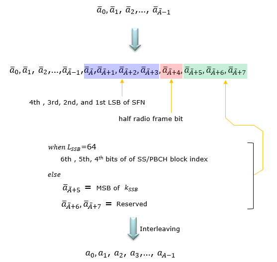
The BCH data sequence begins with bits labeled from ã0 to ã(A-1). This sequence is then augmented with additional bits that encode specific system information:
- The bits ã(A-1), ã(A+1), ã(A+2), and ã(A+3) correspond to the 4th, 3rd, 2nd, and 1st LSBs of the System Frame Number (SFN).
- The bit ã(A+4) denotes a half radio frame bit.
- When LSSB equals 64, the bits ã(A+5), ã(A+6), and ã(A+7) are the 6th, 5th, and 4th bits of the SS/PBCH block index, respectively.
- If LSSB is not equal to 64, then ã(A+5) is the MSB of kSSB, with ã(A+6) and ã(A+7) being reserved.
After these bits are inserted, an interleaving process is applied, reordering the sequence into a0 to a(A-1), which completes the payload generation phase ready for subsequent transmission steps.
(2) Scrambling
The image details the scrambling process for cellular communication data, which is a critical step in the PBCH Transport Process. The process begins with the generation of an initialization sequence cinit that is dependent on the cell ID NcellID and the System Frame Number (SFN). The sequence is specifically generated at the start of each SFN where mod(SFN, 8) equals 0.
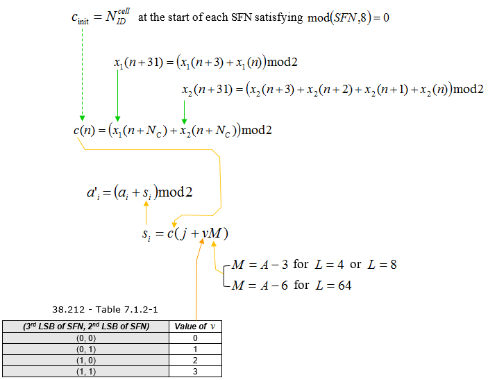
The scrambling sequence c(n) is formulated using two sequences x1(n) and x2(n). These sequences are recursively updated using the relationships:
- x1(n+31) = (x1(n+3) + x1(n)) mod 2
- x2(n+31) = (x2(n+3) + x2(n+2) + x2(n+1) + x2(n)) mod 2
The data bit ai is scrambled with the bit si from the scrambling sequence c(n), resulting in the scrambled bit a'i = (ai + si) mod 2.
The value of si is derived from the pseudo-random sequence generated by c(j + vM), where M is defined as A - 3 for L = 4 or L = 8, and A - 6 for L = 64.
The accompanying table maps the third and second LSB of the SFN to the value of v, which influences the pseudo-random sequence generation:
- For (0, 0), v is 0.
- For (0, 1), v is 1.
- For (1, 0), v is 2.
- For (1, 1), v is 3.
This scrambling ensures the transmitted signal's clarity, distinguishing it from noise and other signals for precise reception and decoding.
(3) CRC Attachment
Following illustrates the CRC Attachment process, which is the third step in the PBCH Transport Process. CRC on a broadcast channel does more than detect errors. The UE has no prior knowledge of which SS/PBCH block it is looking at, so it decodes several hypotheses and uses the CRC to decide which one was right.
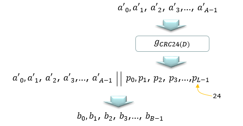
A sequence of scrambled bits is represented as a'0, a'1, a'2, ..., a'A-1. A CRC polynomial, represented as GCRC24(D), is applied to this data sequence, producing a set of CRC bits p0, p1, p2, ..., pL-1, with L being the length of the CRC which is 24 bits.
These CRC bits are then appended to the original data sequence, resulting in an concatenated data string a'0, a'1, a'2, ..., a'A-1 | p0, p1, p2, ..., pL-1. This appended sequence serves as a checksum for error detection at the receiver's end. The combined sequence, now including the CRC, is denoted as b0, b1, b2, ..., bB-1.
The CRC attachment is essential for maintaining data integrity during transmission and is a common practice in digital communication systems for error detection and correction.
(4) Channel Coding
Following diagram presents the Channel Coding step, which is the fourth stage in the PBCH Transport Process. The parameters annotated on the right of the illustration make this a PBCH polar encoder rather than a general one. They are worth reading before the block itself.
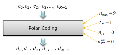
It begins with a sequence of bits, represented as c0, c1, c2, ..., cK-1, which are then fed into a Polar Coding scheme.
Polar Coding transforms the original bits into a new set of coded bits that have properties making them more robust against errors over a noisy communication channel. Parameters such as nmax = 9, IL = 1,npc = 0 and nwmpc = 0 are related to the specific configuration of the Polar Coding process.
The output from the Polar Coding block is a new sequence of coded bits d0, d1, d2, ..., dN-1, which are ready for the subsequent steps in the transmission process. This encoded sequence is designed to be more resilient to the effects of noise and interference when transmitted over the air interface.
(5) Rate Matching
Step five is drawn in the diagram at the top of this page and is named in the list of steps above, but it has had no section of its own until now. It is also the step that fixes the one number everything downstream depends on, so it is worth reading closely rather than skipping.
Polar coding in step four produces a block whose length is a power of two. The space available in the SS/PBCH block is not a power of two, so the two do not meet without an adjustment. 38.212 clause 7.1.5 is that adjustment. It takes the coded sequence d0 to d(N-1) and produces f0 to f(E-1). The rate matching algorithm itself sits in clause 5.4.1.
Figure 1 annotates that output with the number 864, and 864 is where the rest of the chain comes from. Step six scrambles 864 bits. Step seven maps them two at a time onto QPSK symbols, which gives 432 symbols. Step eight has to find 432 resource elements for them.
That last number is not a coincidence, and checking it against 38.211 is the quickest way to see why E is 864 rather than any other value. Table 7.4.3.1-1 gives the PBCH resource elements inside an SS/PBCH block. Symbols 1 and 3 carry subcarriers 0 to 239, which is 240 each. Symbol 2 carries subcarriers 0 to 47 and 192 to 239, which is 96. The total is 576.
38.211 also says the PBCH mapping must skip every resource element reserved for the PBCH demodulation reference signal. 576 elements less the 432 the data needs leaves 144 for the reference signal, which is one element in four. E is 864 because that is exactly what fits once the reference signal has its quarter.
Rate matching is where the block length is decided : polar coding gives a power of two, and the SS/PBCH block is not one, so clause 7.1.5 reconciles the two.864 is the number to remember : it is the rate matching output, the input to the second scrambling, and twice the number of QPSK symbols that follow.The figure works backwards from the resource grid : 576 PBCH resource elements less one in four for DM-RS leaves 432, and 432 QPSK symbols carry 864 bits.Skipping this step hides the arithmetic : without it the 864 in Figure 1 and the M_bit in steps six and seven appear without any origin.
(6) Scrambling
The image illustrates the scrambling process which is step six in the PBCH Transport Process, essential for data preparation in cellular networks. This is the second scrambling in the chain and it does a different job from the first. The first was keyed to the frame number. This one is keyed to the SS/PBCH block index, which is what lets a UE work out which block it received.
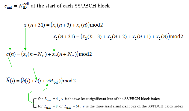
NOTE : Lmax is the maximum number of SS/PBCH blocks in an SS/PBCH period. This value is determined by subcarrier spacing and frequency range. See this table to see the specific Lmax value for each cases.
It begins with the initialization of the sequence cinit based on the cell's NIDcell at the start of each SS/PBCH block.
Two sequences, x1(n) and x2(n), are used to generate the scrambling sequence c(n). These sequences are updated for each n using a linear feedback shift register, with updates performed as follows:
- x1(n+31) = (x1(n+3) + x1(n)) mod 2
- x2(n+31) = (x2(n+3) + x2(n+2) + x2(n+1) + x2(n)) mod 2
The data bits b̃(i) are scrambled by XORing with the bits from the sequence c(i + vMbit), where Mbit is a variable that depends on the length Lmax of the SS/PBCH block index:
- For Lmax = 4, v is the two least significant bits of the SS/PBCH block index.
- For Lmax = 8 or Lmax = 64, v is the three least significant bits of the SS/PBCH block index.
This step is crucial to ensure that the transmitted signal is robust against interference, enabling accurate decoding by the receiver.
(7) Modulation
The image depicts the Modulation process Only one modulation order is ever used here, and that is the point. PBCH has to be decodable at the edge of the cell by a UE that has no channel estimate yet. The scheme is therefore fixed at the most robust option rather than adapted.
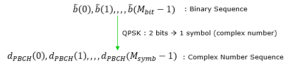
The process starts with a binary sequence b̃(0), b̃(1), ..., b̃(Mbit - 1). This binary sequence is then modulated using QPSK, which maps every two bits of the binary sequence to one complex number symbol, thereby creating a complex number sequence dPBCH(0), dPBCH(1), ..., dPBCH(Msymb - 1).
QPSK is a type of modulation that is particularly efficient in terms of spectrum usage because it transmits two bits per symbol, which is represented as a complex number. After modulation, the data is represented in a format suitable for transmission over a radio frequency channel, with the sequence now prepared to be mapped onto the resource elements of the carrier frequency.
(8) Resource Element Mapping
The 432 symbols from step seven have to be placed somewhere, and the place is fixed rather than scheduled. 38.211 Table 7.4.3.1-1 sets out the resource elements an SS/PBCH block reserves for PBCH, and the mapping fills them in increasing order of subcarrier and then symbol.
- Symbols 1 and 3 of the SS/PBCH block carry PBCH across subcarriers 0 to 239.
- Symbol 2 carries PBCH on subcarriers 0 to 47 and 192 to 239 only, because SSS occupies the middle of that symbol.
- The mapping skips every resource element reserved for the PBCH demodulation reference signal.
- The frequency domain placement of the block as a whole is a separate question, and the page linked below covers it.
Refer to Frequency Domain Allocation of SS Block page.
RRC Parameters
The main purpose of PBCH is to carry(broadcast) MIB. See Master Information Block section for the details of MIB. The name of this section is slightly misleading, because there is no PBCH configuration for RRC to send. PBCH is the one channel a UE must read before any RRC message has arrived.
That constraint explains most of the design above. Everything the UE needs in order to decode PBCH has to be either fixed by the specification or derivable from what the UE already has. The cell identity comes from PSS and SSS, and it seeds both scrambling steps. The block index comes from the DM-RS sequence and the payload itself, and it seeds the second one. Nothing here is configured.
The payload runs the other way. The MIB that PBCH carries is what makes the first RRC message reachable, because it points at the CORESET and search space where SIB1 is scheduled. PBCH is therefore the boundary between what is fixed and what is configured, which is why it appears in no RRC listing on this page.
PBCH takes no configuration : it is decoded before any RRC message exists, so every parameter it needs is fixed or derived rather than signalled.The cell identity does the seeding : the same physical cell identity recovered from PSS and SSS initialises the scrambling in step two and step six.The payload is the configuration : the MIB inside PBCH is what tells the UE where to find SIB1, so the flow of configuration starts here rather than arriving here.
Reference
[1] 3GPP TS 38.212 - NR; Multiplexing and channel coding. Clause 7.1 covers steps one to five, from payload generation through rate matching.
[2] 3GPP TS 38.211 - NR; Physical channels and modulation. Clause 7.3.3 covers steps six to eight, and Table 7.4.3.1-1 gives the resource elements PBCH occupies.