As of now (Jun 2016), there is no determined technical details (or agreement) in 3GPP. However, from recent RAN1 meetings several technical proposals started coming out. So it might be a good time to start following up technical issues on Massive MIMO happening in 3GPP.
That sentence dates the page, and the answer arrived some time later. It is worth saying up front that 3GPP never picked one of these architectures. What did 3GPP actually specify in the end ? at the bottom of this page covers where the question went instead.
- Overall System Architecture
- How / Where to implement the Massive MIMO
- What did 3GPP actually specify in the end ?
- Reference :
Overall System Architecture
First, let's think of overal system architecture of Massive MIMO. One example architecture proposed in R1-164708 ([1]) is as below. At the beginning of the process is a Baseband Unit and at the end is Physical Antenna Array. In between these two end points, there is special unit called Radio Distribution Network (RDN). The data out of the baseband unit is carried to the Radio Distribution Network through a set of TXRUs, where TXRU stands for Transceiver Unit.
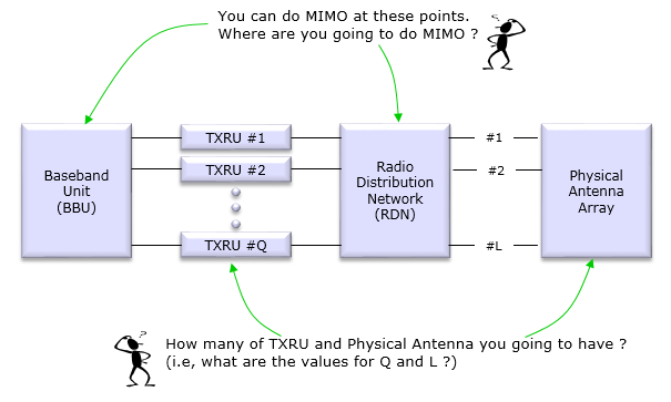
< R1-164708 - Where to apply the MIMO >
The two stick figures in the R1-164708 illustration mark the questions that decide everything else. Where do you apply the beamforming, and how many of each box do you build ?
Two counts are named there and then used in every bullet list further down, so they are worth fixing now. Q is the number of TXRUs, drawn as TXRU #1 through TXRU #Q. L is the number of physical antenna elements, drawn as #1 through #L.
A TXRU is a Transceiver Unit. It is a complete radio chain with its own converter, mixer and amplifier, and it is the expensive item in the diagram. The RDN between the TXRUs and the elements is a network of splitters and phase shifters, and it is comparatively cheap.
The ratio of L to Q is the one number that classifies everything below. When L equals Q, every element has its own radio chain. When Q is one, a single chain drives the whole array. Everything between those two is hybrid.
The three referenced documents label these quantities differently, which the page notes later on. The mapping is small enough to give here.
|
Quantity |
R1-164708 |
R1-165179 |
|---|---|---|
|
data streams entering the precoder |
not labelled |
S |
|
digital chains, one per TXRU |
Q |
N_D |
|
antenna elements per digital chain |
L / Q |
N_A |
|
physical antenna elements in total |
L |
N_A x N_D |
R1-165362 uses a third set of labels. It names the chains TX-1 through TX-Q, and it counts beams rather than elements. K is the number of streams entering the digital stage, and B is the number of beams formed in the analog stage.
How / Where to implement the Massive MIMO
Basically you can do something on MIMO at two level, one is at Baseband Unit level and the other is at RF level. And as you can easily guess, there can be possibility of combining the both. Depending on how/where to implement the MIMO, R1-164708 categorize three different types of implementation as summarized below.
Before the three types, it helps to see them as one trade rather than three separate ideas. Beamforming applies a weight to each element, and the only real question is where that weight is applied.
A weight applied in the baseband is a complex multiplication. It can differ from one sub-band to the next, it can change every slot, and it costs nothing but arithmetic. A weight applied in the RF domain is a phase shifter. It acts on the whole carrier at once, and it changes slowly.
That single difference explains every bullet in the three lists below. Digital weights buy frequency selectivity and per user precision. Analog weights buy a large array without paying for a radio chain at every element.
< Figure 1. The three architectures on one axis >
Figure 1 places the three on the same axis, which is the number of elements per radio chain. The left end pays for a chain per element and gets full freedom. The right end pays for almost nothing and gets one wide-band beam.
|
Fully digital |
Hybrid |
Fully analog |
|
|---|---|---|---|
|
TXRU count |
Q = L |
1 < Q < L |
Q = 1 |
|
where the weights sit |
baseband |
baseband and RF |
RF |
|
frequency selective |
yes, per sub-band |
in the digital part only |
no, wide-band only |
|
beams at one time |
up to Q |
up to Q |
one |
|
converters needed |
one pair per element |
one pair per chain |
one pair |
|
what limits it |
cost and power of L chains |
Q caps the stream count |
no per user precision |
Fully Digital Architecture
In this architecture, MIMO/Beamforming is fully done by baseband unit (BBU) meaning MIMO is fully done purely mathematically. Practically RDN is not doing anything. However, we cannot add and remove the hardware while the system is working. So RDN will be still there even in Fully Digital Architecture. In this case, RDN sets a specifically fixed configuration and passes data from TXRU directly to Physical Antenna.
Followings are some of the illustrations based on several different references. As you see, the terminology is a little bit different in different documents, but I left those terminology as in the original documents. It would be good chance to see a little bit different versions of presentation for a same concept.
R1-165179 draws the digital case at its simplest, with the converter count made explicit.
Illustration Based on R1-165179
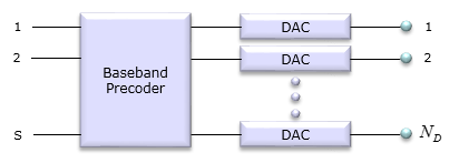
S streams enter the baseband precoder, and each of its N_D outputs goes to its own DAC. Every DAC then feeds one antenna, with nothing in between. No phase shifter appears anywhere in the drawing, and that absence is the defining feature. N_D is therefore both the converter count and the element count.
R1-165362 draws the same architecture, but counts beams where R1-165179 counts converters.
Illustration Based on R1-165362
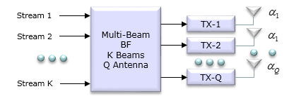
The single block on the left forms K beams across Q antennas, and it forms them mathematically. Each TX chain that follows drives exactly one element, marked with its own coefficient. Reading the two drawings together shows one structure counted two ways, once by converter and once by beam.
Several characteristics of this architecture are as follows :
- This is the structure that we are using in current LTE
- The number of TXRU should be at least two, meaning Q >= 2.
- This architecture is suitable when Q and L are comparable (similar)
- MIMO/Beamforming in this architecture can be wide-band wise and sub-band wise
- (However) it is difficult to use this architecture in very wideband because it requires very high speed ADC/DAC which cause very large energy consumption.
- It would generate too much cost if the number of antenna gets large because each antenna requires its own transceiver unit.
Fully Analog/RF Architecture
In this architecture, there is no MIMO/Beamforming at BBU level. It is done by RDN which means it is done at RF level.
Followings are some of the illustrations based on several different references. As you see, the terminology is a little bit different in different documents, but I left those terminology as in the original documents. It would be good chance to see a little bit different versions of presentation for a same concept.
R1-165179 draws the analog case as the exact opposite of its own digital one.
Illustration Based on R1-165179
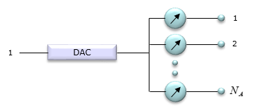
One stream enters and one DAC follows it, so Q equals one. The split into N_A branches happens after the converter, and each branch carries a phase shifter, drawn as an arrow inside a circle. All of the beamforming therefore sits in hardware, downstream of the only converter in the diagram.
R1-165362 draws a more general analog case, and the difference from the previous drawing is worth noticing.
Illustration Based on R1-165362
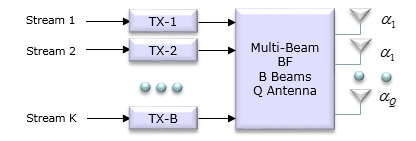
Here K streams enter, and there are B transmit chains rather than a single one. The point is that no precoding happens across those chains. The whole beamforming block sits after them, in the RF domain, and that is what makes the case analog rather than hybrid. Fully analog constrains where the weights are applied, not how many chains exist.
Several characteristics of this architecture are as follows :
- This architecture is suitable when L is much greater than Q ( L >> Q)
- MIMO/Beamforming in this architecture is wide-band wise
Hybrid Architecture
As name implies, in this architecture MIMO/Beamforming happens both at BBU and RDN. It doesn't mean that the exact the same MIMO/Beamforming happens twice. It means that the final effect of MIMO/Beamforming is splitted into two separate parts (BBU and RDN).
Followings are some of the illustrations based on several different references. As you see, the terminology is a little bit different in different documents, but I left those terminology as in the original documents. It would be good chance to see a little bit different versions of presentation for a same concept.
R1-165179 builds its hybrid drawing by placing its own two earlier drawings end to end.
Illustration Based on R1-165179
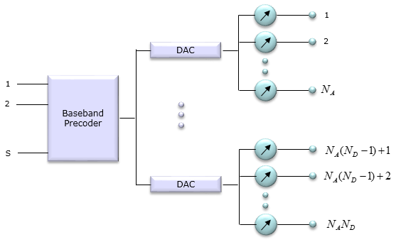
The baseband precoder takes S streams and produces N_D outputs, which is the digital layer. Each DAC then feeds its own group of N_A phase shifters, which is the analog layer. Multiplying the two gives N_A times N_D elements driven by only N_D converters. Note that no element is shared between converters, so this drawing is already a sub array configuration.
The fully connected configuration places one shared beamforming network after the transmit chains.
Illustration Based on R1-165362 : Fully Connected Configuration
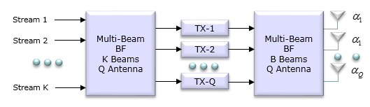
Two Multi-Beam BF blocks appear here, one before the TX chains and one after them. The second block spans every antenna, so every chain can reach every element. That reach is what fully connected means, and it is paid for with Q times L phase shifters.
The sub array configuration replaces that shared network with one small network per chain.
Illustration Based on R1-165362 : Sub Array Configuration
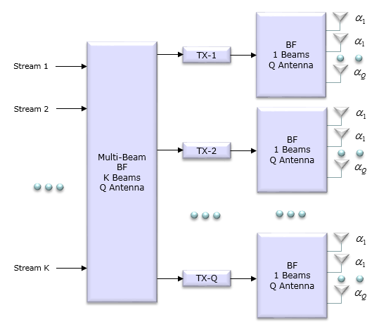
Each TX chain now owns its own BF block, marked as forming a single beam over its own antennas. No element appears under more than one chain. The phase shifter count falls to L, and in exchange each stream is limited to the aperture of its own block.
Several characteristics of this architecture are as follows :
- Q sits strictly between 1 and L, so the array is larger than the number of radio chains.
- The digital part can still be frequency selective, and the analog part cannot.
- The number of streams at one time is limited by Q, and never by L.
- The number of converters follows Q rather than L, which is what keeps the power consumption tolerable at wide bandwidth.
- It suits the case where L is large and a chain per element is not affordable, which is the usual situation at millimetre wave.
Fully connected and sub array are not the same thing
The last two illustrations show two ways of wiring the analog part. The difference matters more than the drawings suggest, and it is the main design choice inside a hybrid array.
In the fully connected configuration every TXRU reaches every antenna element. That needs Q times L phase shifters, and each stream can use the whole aperture. The beamforming gain available to one stream is the full array gain.
In the sub array configuration each TXRU drives its own separate block of elements, and no element is shared. That needs L phase shifters in total, which is Q times fewer. Each stream only reaches its own block, so its gain follows the block size instead of the whole array.
|
Fully connected |
Sub array |
|
|---|---|---|
|
phase shifters |
Q x L |
L |
|
aperture available to one stream |
the whole array |
one block of L / Q elements |
|
wiring |
every chain to every element |
each chain to its own block |
|
build |
one large network |
repeated identical panels |
So fully connected spends hardware to buy gain and flexibility, and sub array gives up gain to save hardware. Sub array is also easier to manufacture, because each block is a self contained panel that can be repeated.
What did 3GPP actually specify in the end ?
This page was written while RAN1 was still collecting proposals, and the opening paragraph says so. The outcome is worth recording, because it is not the kind of answer the question expects.
3GPP did not standardise any of these three architectures. It did not choose fully digital, or hybrid, or fully analog, and it did not fix a value for Q or for L. None of those terms appear as normative requirements.
What the specification defines instead is the antenna port. A port is a logical entity defined by a reference signal, so it describes what the UE can measure rather than what the operator built. Everything normative sits above that line.
So the specification fixes how many CSI-RS ports a UE can be asked to measure. It also fixes how those ports are arranged for the codebook, and what the UE reports back. In the Rel-17 ASN.1 the CSI-RS resource declares nrofPorts as ENUMERATED {p1, p2, p4, p8, p12, p16, p24, p32}, so 32 is the ceiling.
Behind those ports a vendor may build any of the three architectures. A fully digital array of 32 elements and a hybrid array of 256 elements presenting 32 ports look the same to the UE. Separating ports from antennas is exactly what makes that possible, and Antenna elements, TXRUs and antenna ports works through the distinction.
The architecture question did not disappear. It moved from the specification to the product and the datasheet, and the trade drawn in Figure 1 is still the same trade.
The interface is standardised, not the radio : Ports, codebooks and reports are normative, while Q and L are not.The port count is the visible ceiling : NR stops at 32 CSI-RS ports whatever sits behind them.The choice became commercial : Vendors pick along the axis in Figure 1 according to band, bandwidth and cost.
Reference :
[1] R1-164708 : 3GPP TSG-RAN WG1 #85 - NR Massive MIMO Design Considerations
[2] R1-165179 : 3GPP TSG-RAN WG1 #85 - Multi-Antenna Technology for NR Interface
[3] R1-165362 : 3GPP TSG-RAN WG1 #85 - Multi-antenna Architectures and Implementation Issues in NR