5G/NR - Interworking with LTE  


Interworking with LTE - NSA / ENDC in a Nutshell


  • There are two types of LTE - NR interworking : ENDC and NEDC
  • In ENDC (Eutra / NR Dual Carrier), Eutra (LTE) become MCG(Main Cell Group) and NR become SCG(Secondary Cell Group), meaning that LTE is main cell and NR just work as a secondary cell.
  • In NEDC (NR/Eutra Dual Carrier), NR become MCG(Main Cell Group) and Eutra (LTE) become SCG(Secondary Cell Group), meaning that NR is main cell and LTE just work as a secondary cell.
  • ENDC is dominant form of deployment, NEDC is just done in specification, I personally haven't seen any example of real deployment.
  • In ENDC, Core Network is based on LTE Core, NR just provide additional RAN pipe.
  • In ENDC, Downlink traffic is always split between LTE and NR, but there is two options for Uplink traffic.
    • Option 1 : All the uplink goes through LTE only
    • Option 2 : Uplink gets split between LTE and NR. The ratio of the split is configured by RRC
  • When NR is added to the LTE cell, UE should be able to detect SSB of NR cell and perform RACH procedure to NR

Interworking with LTE - NSA / ENDC in Detail

This is about one of NR deployment options where LTE work as a master and NR work as a secondary cell (In 3GPP terms, this is about EN-DC (EUTRA-NR Dual Connectivity) / MR-DC with EPC as described in 37.340). In this configuration, UE get connected to LTE network first and then connected to NR via RRC Connection Reconfiguration process. Further details on lower layer process is yet to be studied, but just looking into the conentents of RRCConnectionReconfiguration would give you some general idea about the mechanism.
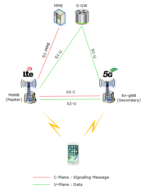
Overall Network Architecture

Overall RAN architecture of EN-DC can be illustrated as below (this is based on 37.340 - 4.3.1 and 4.3.2). As you see here, UE is communicating with both LTE eNB and NR gNB in Radio side, but all those communication (signaling and data) are going through LTE core network. Though not shown in this illustration, I would point out that LTE eNB and NR gNB are using their own PHY/MAC (i.e, independent MAC Scheduler)).

As you see here, in case of data plane both Master Node(LTE) and Secondary Node(gNB) has direct interface with LTE corenetwork(S-GW), but in case of control plane only Master Node(LTE) has direct interface with LTE core network(MME).

NOTE : This illustration is just to give you the big picture of how 4G/5G RAN connected to each other and how they are connected to core network (EPC). It is based on general concept of Option 3, but not showing any specific variation of the option (e.g, plain option 3 or 3a or 3x). For further details of those deployment options, refer to Deployment Scenario page and some references linked in the page.

Now let's read the picture. If you take a close look at the illustration and just describe it in words, you would get the descrition as follows. If you don't like reading (like me :), just take 10 minutes (not 10 seconds) and look thorugh each and every part and lines of the picture.
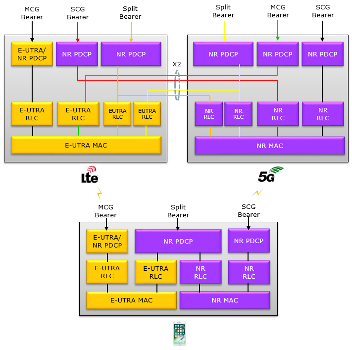
  •   For C-Plane
    •   There is an interface between MN(Master Node : MeNB in this csae) and the SN (Secondary Node : En-gNB in this case). This interface is called X2-C.
    •   There is an interface between MN and CN(Core Network : MME in this case). This interface is called S1-MME.
    •   There is NO direct interface(connection) between SN and CN
  •   For U-Plane
    •   There is an interface between MN(Master Node : MeNB in this csae) and the SN (Secondary Node : En-gNB in this case). This interface is called X2-U.
    •   There is an interface between MN and CN(Core Network : MME in this case).  This interface is called S1-U
    •   There is an interface(connection) between SN and CN. This interface is called S1-U.

Overall Layer 2 Architecture

Following is based on 37.340 - Figure 4.2.2-3 and Figure 4.2.2-1. As mentioned before, there are roughly two options when LTE and NR interplay. One option is to make LTE as a master and NR as a slave. The other option is to make NR as a master and LTE as a slave. In real deployment, especially at the early deployment, the first option (i.e, LTE Master and NR Slave) would be the major deployment option. This illustration is also to show the overal radio stack structure of LTE Master and NR Slave.

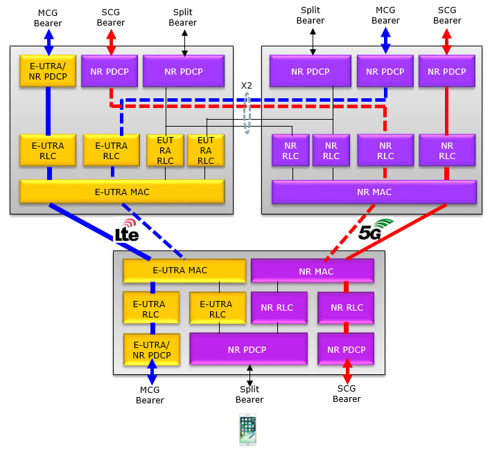
Various types of Bearer for LTE-NR Interworking (EN-DC)

In terms of Over The Air(OTA) and Physical Layer perspective, LTE-NR interworking (EN-DC) in NSA(Non-StandAlone) is only one possibility (assuming that LTE always becomes the Anchor), but with the same OTA/Physical layer there can still be multiple possibilities of implementing higher layer bearer.

38.331 - 5.3.1.1 RRC connection control states as follows :

    In case of EN-DC, the SCG cells use another RAT, namely NR. When configured with EN-DC, user data carried by a DRB may either be transferred via MCG, via NR SCG or via both MCG and NR SCG. Also RRC signalling carried by a SRB may either be transferred via MCG or via both MCG and NR SCG. When DRBs and SRBs are configured with transmission via both MCG and SCG, duplication may be used in both DL and UL.

I just tried to turn this statement into illustration as follows (This illustration is based on 37.340 - Figure 4.2.2-3 and Figure 4.2.2-1)  :

The statement 'DRB may either be transferred via MCG, via NR SCG or via both MCG and NR SCG' can be illustrated as follows.

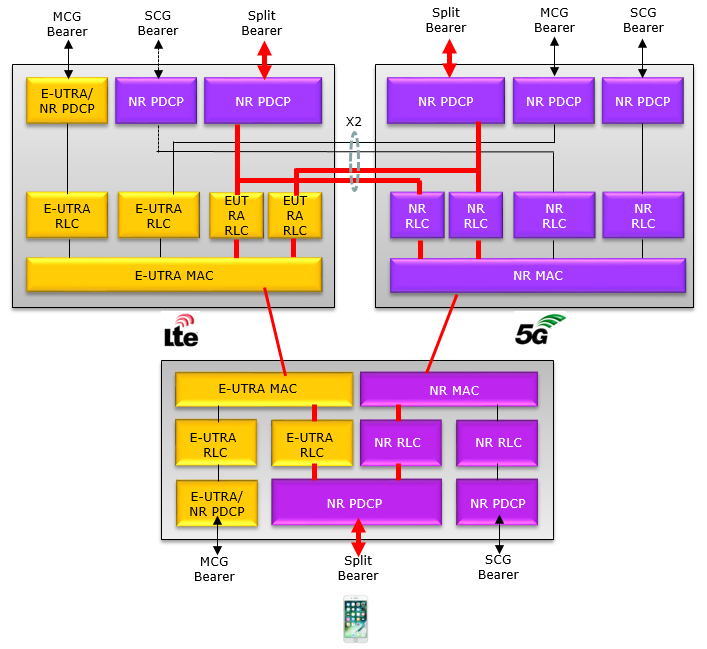
There is another bearer type called split Bearer (or split DRB). It can be illustrated as follows. You may find more details about this in Split Bearer page.

Types of NR(SCG) addition in EN-DC(LTE+NR Interworking)

In ENDC(Eutra NR Dual Connectivity), LTE would become a MCG(Master Cell Group) and NR would become a SCG(Secondary Cell Group). MCG work as the anchor and UE performs initial registration to this anchor cell group, and this anchor cell add one or more Secondary Cells (SCG). In 36.331-5.3.1.1, there are three different types(ways) of adding SCGs to the LTE anchor cell as follows.

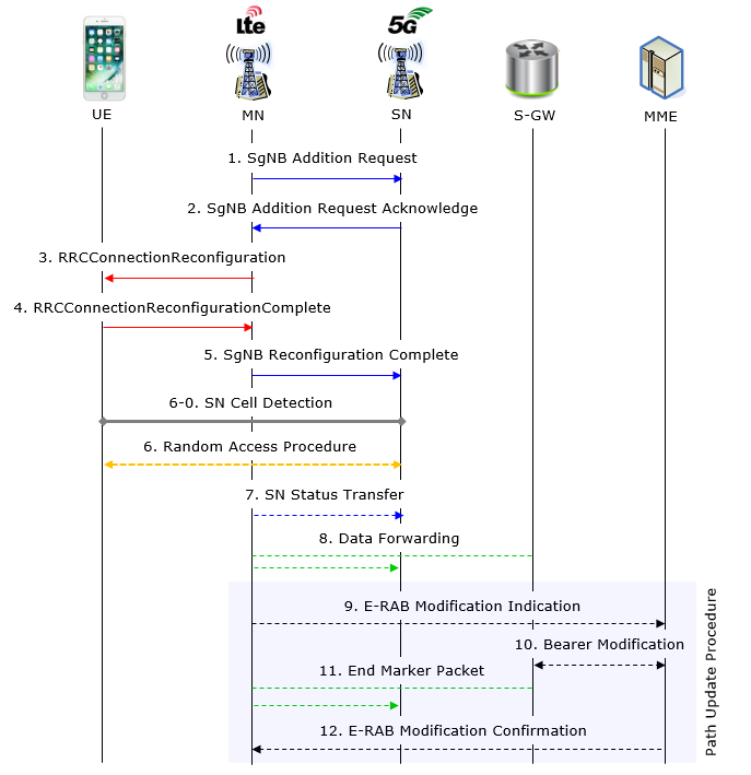
    Type 1 : Reconfiguration with sync and key change

      •   Perform RA Procedure to PScell
      •   Reset NR MAC
      •   Re-establish NR RLC
      •   Re-establish NR PDCP
      •   Refresh  NR SCG security

    Type 2 : Reconfiguration with sync but without key change

      •   Perform  RA to the PSCell,
      •   Reset NR MAC
      •   Re-establish NR RLC re-establishment and
      •   Re-establish PDCP data recovery (for AM DRB)

    Type 3 : Regular NR SCG reconfiguration without Sync / SCG Security

      •   Does not perform RA to the PScell
      •   Does not refresh NR SCG security
      •   Reset NR MAC
      •   Re-establish NR RLC

Overall Signaling Procedure

This section is about how to add NR cell(Secondary Node) to an existing LTE Cell.(Master Note). Overall signaling flow is illustrated below. This flow is based on 37.340 - 10.2.1 except the step 6-0 which is added by me. As you may notice,the process is iniated by MN (Master Node : LTE eNB in this case) and final confirmation is done by MME.

< 37.340 - Figure 10.2.1-1: Secondary Node Addition procedure >


Step 1 : MN (Master Node : LTE eNB) send SgNB Addition Request to SN (Secondary Node : NR gNB in this case). LTE eNB forward following informations to NR gNB.

  •   E-RAB Characteristics (E-RAB Parameters, TNL address information)
  •   The requested SCG configuration information including the entire UE capabilities and UE capability coordination result
  •   The latest measurement result for SN to choose
  •   Securiy Information to enable SRB3
  • In case of bearer option that requires X2-U between MN and SN
    •   X2-U TNS address information
  •   In case of SN terminated split bearers,
    •   the maximum supportable QoS level

Step 2 : (If SN decided to accept the request), it sends SgNB Addition Request Acknowlege performing followings

  •   Allocate the necessary radio resources transport network resources
  •   decides Pscell and other SCG Scells and provide the new SCG radio resource configuration to MN
  •   In case of bearer options that requires X2-U between MN and SN
    •   provides X2-U TNS address informations
  •   In case of SCG radio resources being requested
    •   provide SCG radio resource configuration

Step 3 : If NR gNB accept the SN addition request and provides all the necessary information to LTE eNB, LTE eNB generate RRC Connection Reconfiguation message carrying all the necessary information and send it to UE. This message carries NR RRC Connection Cofiguration in it so that UE can figure out the necessary configuration information for NR gNB.

Step 4  : After UE received RRCConnectionReconfiguration, it checks if all the configurations in the message is doable in UE side, it sends RRCConnectionReconfigurationComplete message. This message includes NR RRC Response as well.

Step 5  : Once MN (LTE eNB) received RRCConnectionReconfigurationComplete from UE, the MN informs SN(NR gNB) that UE has completed the reconfiguration procedure.

Step 6-0  : Based on the information contained in NR RRCConnectionConfiguration within RRC Connection Reconfiguration message, UE detects SSBlock(PSS, SSS and PBCH) of NR gNB.  For the details of SSBlock, see SSBlock page.

Step 6  : Once it successfully detects PSS, SSH, PBCH of NR gNB, it performs RACH procedure to PSCell of the SN (NR gNB). UE aquire all the information required for RACH procedure from RRC Connection Reconfiguration message instead of SIB, this process is described in RACH Process for LTE-Interworking(ENDC) .

Following is a summary of overall NSA procedure which would give you more practical sense. This would be the most common NSA protocol sequence that you may see from RRC/NAS log.

Direction

Message/Procedure

Comments

UE <-- NW

SIB2 with 5G support indication

See this note for an example

UE <-> NW

< LTE Initial Attach Start>


...


UE <-- NW

UECapabilityInformqtionEnquiry

NW request UE to notify NR capability

UE --> NW

UECapabilityInformation

UE Report NR capability. See this note


...


< LTE Initial Attach Complete>


UE <-- NW

RrcConnectionReconfiguration for NR Cell Measurement

See this note for an example

UE --> NW

RrcConnectionReconfigurationComplete


UE --> NW

MeasurementReport with NR Cell Measurement

See this note for an example

UE <-- NW

RrcConnectionReconfiguration for NR Addition

See this note for the details

UE --> NW

RrcConnectionReconfigurationComplete


UE <-> NW

Peform RACH process to NR Cell

See this note for an example

LTE RRC Configuration

The major role of RRC in LTE-NR Interworking(more specifically ENDC) is to add NR as a secondary cell to LTE Anchor cell. The major IE(information elements) related to this process are

  •   nr-Config
  •   nr-SecondaryCellGroupConfig
  •   nr-RadioBearerConfig1

These few IEs has very complicated structures in it and carries so much information. Basically they carries all the information that combines MIB, SIB and RRC Configuration messages in standalone NR.  I will take a while to get the detailed understanding on each and every elements of informations in it. Followings are rough summary of informations carried by the RRC Connection Reconfiguration message.

Function (Information)

Description

Frequency and Bandwidth

     in NR Downlink

spCellConfigCommon.frequencyInfoDL

spCellConfigCommon.initialDownlinkBWP

Frequency and Bandwidth

     in NR Uplink

spCellConfigCommon.uplinkConfigCommon.frequencyInfoUL

spCellConfigCommon.uplinkConfigCommon.initialUplinkBWP

PRACH to NR

spCellConfigCommon.uplinkConfigCommon.initialUplinkBWP.rach-ConfigCommon

PDCCH Configuration

     to decode RAR(PDSCH)

spCellConfigCommon.initialDownlinkBWP.pdcch-ConfigCommon

PDSCH Configuration

     to send RAR(PDSCH)

spCellConfigCommon.initialDownlinkBWP.pdsch-ConfigCommon

PUSCH Configruation

     for Common Channel

spCellConfigCommon.uplinkConfigCommon.initialUplinkBWP.PUSCH-ConfigCommon

PDCCH Configuration

     for dedicated channels

(msg4 and onwards)

spCellConfigDedicated.initialDownlinkBWP.pdcch-Config

PDSCH Configuration

     for dedicated channels

(msg4 and onwards)

spCellConfigDedicated.initialDownlinkBWP.pdsch-Config

PUCCH Configruation

     for Dedicated Channel

(msg4 Ack/Nack and onwards)

spCellConfigDedicated.initialDownlinkBWP.pdcch-Config

PUSCH Configruation

     for Dedicated Channel

(msg4 Ack/Nack and onwards)

spCellConfigDedicated.initialDownlinkBWP.pdcch-Config

tdd UL/DL Configuration

spCellConfigCommn.tdd-UL-DL-ConfigurationCommon

spCellConfigDedicated.tdd-UL-DL-ConfigurationDedicated


RRCConnectionReconfiguration-v1430-IEs ::= SEQUENCE {

    sl-V2X-ConfigDedicated-r14      SL-V2X-ConfigDedicated-r14      OPTIONAL,   -- Need ON

    sCellToAddModListExt-v1430      SCellToAddModListExt-v1430      OPTIONAL,   -- Need ON

    perCC-GapIndicationRequest-r14  ENUMERATED{true}                OPTIONAL,   -- Need ON

    systemInformationBlockType2Dedicated-r14    

                               OCTET STRING (CONTAINING SystemInformationBlockType2)  OPTIONAL,

    nonCriticalExtension            RRCConnectionReconfiguration-v15x0-IEs      OPTIONAL

}


RRCConnectionReconfiguration-v1510-IEs ::= SEQUENCE {

    nr-Config-r15                   CHOICE {

        release                         NULL,

        setup                           SEQUENCE {

            endc-ReleaseAndAdd-r15  BOOLEAN,

            nr-SecondaryCellGroupConfig-r15 OCTET STRING        OPTIONAL,   -- Need ON

            p-MaxEUTRA-r15                  P-Max               OPTIONAL    -- Need ON

        }

    }                                                           OPTIONAL,   -- Need ON

    sk-Counter-r15                  INTEGER (0.. 65535)         OPTIONAL,   -- Need ON

    nr-RadioBearerConfig1-r15       OCTET STRING                OPTIONAL,   -- Need ON

    nr-RadioBearerConfig2-r15       OCTET STRING                OPTIONAL,   -- Need ON

    tdm-PatternConfig-r15           CHOICE {

        release                         NULL,

        setup                           SEQUENCE {

            subframeAssignment-r15          SubframeAssignment-r15,

            harq-Offset-r15                 INTEGER (0.. 9)

        }

    }                                                           OPTIONAL,   -- Need ON

    nonCriticalExtension            SEQUENCE {}                 OPTIONAL

}


RRCConnectionReconfiguration-v15x0-IEs ::= SEQUENCE {

    endc-Config-r15             SEQUENCE {

        scg-ConfigReleaseNR-r15             BOOLEAN,

        sk-Counter-r15                      INTEGER (0.. 65535)    OPTIONAL,   -- Need ON

        nr-SecondaryCellGroupConfig-r15     OCTET STRING           OPTIONAL,   -- Need ON

        nr-RadioBearerConfig-r15            OCTET STRING           OPTIONAL,   -- Need ON

        nr-RadioBearerConfigS-r15           OCTET STRING           OPTIONAL,   -- Need ON

        tdm-PatternSingle-Tx-r15            SEQUENCE {

            subframeAssignment-r15              SubframeAssignment-r15,

            harq-Offset-r15                     INTEGER (0.. 9)    OPTIONAL    -- Need ON

            }                       OPTIONAL    -- Need ON

    }                                                              OPTIONAL    -- Need ON  

        nonCriticalExtension            SEQUENCE {}                OPTIONAL

}


nr-SecondaryCellGroupConfig1-r15,nr-SecondaryCellGroupConfig2-r15 : Includes NR RRCReconfiguration message.

                                             The field includes the configuration of RBs configured with NR PDCP.

nr-RadioBearerConfig : Include NR RadioBearerConfig. Mainly for DRB, EPS, NR PDCP Configuration


RRCConnectionResume-v15x0-IEs ::= SEQUENCE {

    sk-Counter-r15                      INTEGER (0.. 65535)         OPTIONAL,   -- Need ON

    nr-RadioBearerConfig-r15            OCTET STRING                OPTIONAL,   -- Need ON

    nr-RadioBearerConfigS-r15           OCTET STRING                OPTIONAL,   -- Need ON

    nonCriticalExtension                SEQUENCE {}                 OPTIONAL

}

Example >

As mentioned above, RRC Connection Reconfiguration in LTE for Adding NR Cell carries only a couple of container that carries a huge tree of NR RRC message.  Due to the complicated RRC structure in NR, I found it difficult to put the whole structure and description of any NR RRC message in a single page. In this example, you will see a couple of starting points of NR RRC part as shown below and you should follow the link until you reach the final destination.

NOTE : If you want to see the contents of full log with Amarisoft Log viewer, go to LogAnalysis section and click on 'Sample Log' in this tutorial of Amarisoft TechAcademy.

rrcConnectionReconfiguration

    measConfig

    mobilityControlInfo

    dedicatedInfoNASList

    radioResourceConfigDedicated

    nonCriticalExtension

        laterNonCriticalExtension

        nonCriticalExtension

            otherConfig-r9

            fullConfig-r9

            nonCriticalExtension

                sCellToReleaseList-r10

                sCellToAddModList-r10

                nonCriticalExtension

                    systemInformationBlockType1Dedicated-r11

                    nonCriticalExtension

                        wlan-OffloadInfo-r12

                        scg-Configuration-r12

                        sl-SyncTxConfrol-r12

                        sl-DiscConfig-r12

                        sl-CommonConfig-r12

                        nonCriticalExtension

                            sCellToReleaseListExt-r13

                            sCellToAddModListExt-r13

                            lwa-Configuration-r13

                            lwip-Configuration-r13

                            rdwi-Configuration-r13

                            nonCriticalExtension

                                sl-V2X-ConfigDedicated-r14

                                sCellToAddModListExt-v1430

                                perCC-GapIndicationRequest-r14

                                systemInformationBlockType2Dedicated-r14

                                nonCriticalExtension

                                    nr-Config-r15

                                        endc-ReleaseAndAdd-r15

                                        nr_SecondaryCellGroupConfig-r15

                                            cellGroupID

                                            rlc-BearerToAddModList

                                            mac-CellGroupConfig

                                            physicalCellGroupConfig

                                            spCellConfig 

                                                servCellIndeix

                                                reconfigurationWithSync

                                                   spCellConfigCommon

                                                      physCellId

                                                      frequencyInfoDL

                                                      initialDownlinkBWP

                                                         genericParameters

                                                         pdcch_ConfigCommon

                                                            setup

                                                               commonControlResources

                                                               commonSearchSpaces

                                                               searchSpaceSIB1

                                                               searchSpaceOtherSystemInformation

                                                               pagingSearchSpace

                                                               ra_ConfrolResourceSet

                                                               ra_SearchSpace

                                                         pdsch_ConfigCommon

                                                            setup

                                                               pdsch_AllocationList

                                                      uplinkConfigCommon

                                                         frequencyInfoUL

                                                         initialUplinkBWP

                                                         supplementaryUplinkConfig

                                                      supplementaryUplinkConfig

                                                      ssb_PositionsInBurst

                                                      ssb_periodicityServingCell

                                                      dmrs_TypeA_Position

                                                      lte_CRS_ToMatchAround

                                                      rateMatchPatternToAddModList

                                                      rateMatchPatternToReleaseList

                                                      subcarrierSpacing

                                                      tdd_UL_DL_ConfigurationCommon

                                                         referenceSubcarrierSpacing

                                                         dl_UL_TransmissionPeriodicity

                                                         nrofDownlinkSlots

                                                         nrofDownlinkSymbols

                                                         nrofUplinkSlots

                                                         nrofUplinkSymbols

                                                      tdd_UL_DL_ConfigurationCommon2

                                                      ss_PBCH_BlockPower

                                                      newUE_Identity

                                                      t304

                                                      rach_ConfigDedicated

                                                rlf-TimersAndConstants

                                                rlmInSyncOutOfSyncThreshold

                                                spCellConfigDedicated

                                                   tdd_UL_DL_ConfigurationDedicated

                                                   initialDownlinkBWP

                                                      pdcch_Config

                                                      pdsch_Config

                                                      sps_Config

                                                      radioLinkMonitoringConfig

                                                   downlinkBWP_ToReleaseList

                                                   downlinkBWP_ToAddModList

                                                   firstActiveDownlinkBWP_Id

                                                   bwp_InactivityTimer

                                                   defaultDownlinkBWP_Id

                                                   uplinkConfig

                                                      initialUplinkBWP

                                                      uplinkBWP_ToReleaseList

                                                      uplinkBWP_ToAddModList

                                                      firstActiveUplinkBWP_Id

                                                      pusch_ServingCellConfig

                                                   supplementaryUplink

                                                   pdsch_ServingCellConfig

                                                   csi_MeasConfig

                                                   carrierSwitching

                                                   sCellDeactivationTimer

                                                   crossCarrierScheduleConfig

                                                   tag_Id

                                                   ue_BeamLockFunction

                                                   pathlossReferenceLinking

                                        p_MaxEUTRA-r15

                                    sk-Counter-r15

                                    nr-RadioBearerConfig1-r15

                                    nr-RadioBearerConfig2-r15

                                    tdm-PatternConfig-r15

                                    nonCriticalExtension

Measurement (LTE-NR Measurement)

In real operation, it is expected for LTE to perform the measurement of the NR cell before it tries adding it. When it comes to measurement, first we need to think of what kind of measurement event to be used. And since this is interfrequency/interRAT from the point of LTE we need to think of measurement gap.

In terms of measurement event, we are using the existing event B1 and B2 and not new event is defined for NR measurement(see here for the details), but in terms of measurement gap, we got a lot of new gap patterns for NR measurement(see here for the details).

NOTE : If you want to see the contents of full log with Amarisoft Log viewer, go to LogAnalysis section and click on 'Sample Log' in this tutorial of Amarisoft TechAcademy.

Example 01 >

Following example message is from Amari Callbox and a commercial UE. I am just putting the measurement related part here and refer to this file for the full contents of the message.

  message c1: rrcConnectionReconfiguration: {

    rrc-TransactionIdentifier 0,

    criticalExtensions c1: rrcConnectionReconfiguration-r8: {

      measConfig {

        measObjectToAddModList {

          {

            measObjectId 1,

            measObject measObjectEUTRA: {

              carrierFreq 300,

              allowedMeasBandwidth mbw100,

              presenceAntennaPort1 TRUE,

              neighCellConfig '01'B

            }

          },

          {

            measObjectId 2,

            measObject measObjectNR-r15: {

              carrierFreq-r15 632256,

              rs-ConfigSSB-r15 {

                measTimingConfig-r15 {

                  periodicityAndOffset-r15 sf20-r15: 0,

                  ssb-Duration-r15 sf1

                },

                subcarrierSpacingSSB-r15 kHz30

              },

              quantityConfigSet-r15 1,

              bandNR-r15 setup: 78

            }

          }

        },

        reportConfigToAddModList {

          {

            reportConfigId 1,

            reportConfig reportConfigInterRAT: {

              triggerType event: {

                eventId eventB1-NR-r15: {

                  b1-ThresholdNR-r15 nr-RSRP-r15: 56,

                  reportOnLeave-r15 FALSE

                },

                hysteresis 0,

                timeToTrigger ms100

              },

              maxReportCells 8,

              reportInterval ms120,

              reportAmount r1,

              reportQuantityCellNR-r15 {

                ss-rsrp TRUE,

                ss-rsrq TRUE,

                ss-sinr TRUE

              }

            }

          }

        },

        measIdToAddModList {

          {

            measId 1,

            measObjectId 2,

            reportConfigId 1

          }

        },

        quantityConfig {

          quantityConfigEUTRA {

            filterCoefficientRSRP fc3

          },

          quantityConfigNRList-r15 {

            {

              measQuantityCellNR-r15 {

                filterCoeff-RSRP-r15 fc3

              }

            }

          }

        },

        measGapConfig setup: {

          gapOffset gp0: 16

        }

      },

......

}


  message c1: measurementReport: {

    criticalExtensions c1: measurementReport-r8: {

      measResults {

        measId 1,

        measResultPCell {

          rsrpResult 69,

          rsrqResult 30

        },

        measResultNeighCells measResultNeighCellListNR-r15: {

          {

            pci-r15 500,

            measResultCell-r15 {

              rsrpResult-r15 79,

              rsrqResult-r15 65,

              rs-sinr-Result-r15 89

            }

          }

        }

      }

    }

  }

}

SCG Failure

Various type of failure can happen during NR addition after UE recieves RRC Connection Reconfiguration. When this happens, UE send SCG Failure Information message with various failure cause as listed below. This is based on 38.331 5.7.3.3. You should see 38.331 v15.4 or higher)

Failure type of SCG-FailureInformation


t310-Expiry

This is triggered when UE is experience consecutive Out-Of_Sync at low layer. (Refer to 38.331-7.1.1 for further details.)

Related Parameter : t310, n310, n311


t312-Expiry

(Applicable for failureType-v1610). Not receiving N311 consecutive in-sync indications from lower layers for the SpCell, receiving RRCReconfiguration with reconfigurationWithSync for that cell group after measurement report is triggered ( Refer to 38.331-7.1.1 for further details.)


synchReconfigFailure-SCG

This is triggered when initial synchronization failed.

It is triggered when UE fails to complete NR RACH until T304 expires

Related Parameter : t304 (see 38.331 - 5.3.5.8.3 and 7.1.1 for further details)


randomAccessProblem

This is triggered when random access process has failed

Related Parameter : PreambleTransMax (see 38.331 - 5.7.3.3 for further details)


rlc-MaxNumRetx

This is triggered when the maximum number of retransmissions has been reached

Related Parameter : maxRetxThreshold (see 38.331 - 5.7.3.3 for further details)


srb3-IntegrityFailure

This is triggered when SRB3 Integrity fails (see 38.331 - 5.7.3.3 for further details)


scg-reconfigFailure

This is triggered when Reconfiguration message is not compatible with UE (see 38.331 - 5.7.3.3 for further details)

NOTE : If you speak / understand Korean, you may refer to this YouTube by Sean Mobile Channel(@22:00)

Carrier Aggregation Setup in NR

After you add NR cell to LTE Anchor completing ENDC, you can add other NR cells to establish Carrer Aggregation(CA). The addition of secondary NR cells can be done at the same step as ENDC establishment or done separately after the ENDC Setup. This NR CA process is very similar to LTE CA establishment process. Overall procedure is as shown below.

Step

Direction

Procedure

1

UE <-> NW

Establish ENDC Connection (NR Primary Cell + NR Secondary Cells)

2

UE < NW

NR Secondary Cell Activation by MAC CE


RRC Connection Message Structure for NR Secondary Cells

spCellConfig

    reconfigurationWithSync

        spCellConfigCommon

    spcellConfigDedicated

sCellToAddModList[0]

    sCellIndex

    sCellConfigCommon

    sCellConfigDedicated

sCellToAddModList[1]

    sCellIndex

    sCellConfigCommon

    sCellConfigDedicated

....

sCellToAddModList[n]

    sCellIndex

    sCellConfigCommon

    sCellConfigDedicated

Reference

[1] LTE-NR tight-interworking and the first steps to 5G (Errisson Research Blog)  

[2] 4G-5G Interworking (SamSung)