This page introduces several candiates for 5G Frame Structure before 3GPP finalize the specification. Now (as of Sep 2017) 3GPP official specification (38.211) defines the Frame Structure. If you are interested in some historical aspects of the 5G Frame structure, it would be good to read through this page. However, if you are interested only in the final conclusion on the 5G/NR Frame Structre, refer to 5G/NR Frame Structure Page.
There has been long long discussions on frame structure both in academia and in 3GPP and now we have pretty clear agreements on what a NR(5G) radio frame would look like. I will follow up various discussions about 5G frame structure from early academic discussion to recent 3GPP agreement in this single page so that you can follow through how the idea on frame structure has evolved. Once 3GPP TS 38.211 is released, I will create another page purely based on 3GPP specification.
- Frame Structure Agreement - 3GPP RP 38.802, 38.804
- Frame Structure Candidates - From early TDoc, Academic Papers
Frame Structure Agreement - 3GPP RP 38.802, 38.804
According to TR 38.802 (Ref [17]) section 5.3 and TR 38.804 (Ref [18]) section 5.4.7, it is agreed as follows :
- Maximum channel bandwidth per NR carrier is 400 Mhz in Rel 15.
- All details for channel bandwidth up to 100 Mhz per NR Carrier are to be specified in Rel 15
- One Numerology corresponds to one subcarrier spacing in frequency domain
- At least for single numerology case, candidates of the maximum numbers of subcarrier is 3300 or 6600 in Rel 15
- Subframe Duration is fixed to be 1 ms <== this is a little different from what many people expected. It is likely that one TTI length is much shorter than this to meet the latency requirement
- One TTI duration corresponds to a number of consecutive symbols for one transmission in time domain (TR 38.804 5.4.7)
- The combination of one numerology and one TTI duration determines how transmission is made on physical layer.
- Frame Length is fixed to be 10 ms
- Scalable numerology should allow the subcarrier spacing from 15 Khz to 480 Khz.
- Number of subcarrier per PRB is 12
- Number of OFDM symbols per slot may vary depending on subcarrier spacing
- For subcarrier spacing <= 60, the number of OFDM symbols / slot = 7 or 14
- For subcarrier spacing > 60, the number of OFDM symbols / slot = 14
- Slot Aggregation (data transmission scheduling to span one or multiple slots
- No explicit DC subcarrier is reserved for both Downlink and Uplink
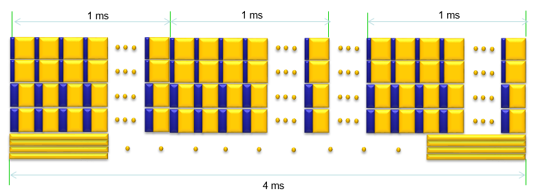
- All numerologies align on symbol boundaries every 1 ms in NR carrier (regardless of subcarrier spacing and CP-overhead)
Following illustration is my interpretation of what is described above (it is difficult to capture every espect in a single diagram, but I hope this can give you some big picture).

Frame Structure Candidates - From early TDoc, Academic Papers
Even thoutgh there are many WhitePapers on 5G issued from many different organizations or companies now (as of Oct 2015), I haven't seen much document touching on Frame Structure of the 5G. As of now (as of Oct 2015), the only documents that I see dealing with these topic are a workshop document from Erricson and a document from METIS.
In this page, I will start with introducing some of idea from these document and keep adding other ideas as I find more documents.
Even though there is no international specification for the detailed frame structure, it would be pretty obvious that the length of the subframe will be much shorter than the one we use in current LTE (1 ms subframe, 10 ms radio frame).
In this page, I will list various kinds of subframe structure with focus of symbol length, subcarrier spacing from various source as if we do brainstorming. I have two reasons why I put all the possibilities here. One is because there is no fixed standards yet and another reason is to give the readers more chance to see more diverse aspects of technical issues determining these basic parameters. Once 3GPP specification is fixed, you may see only very dry description of fixed parameters without any background information about why/how the standard is determined in that specific ways. Following all these ideas or discussions, it will be very helpful for you to understand the final standard when it is available.
Following is the topics discussed in this page.
- Overall Requirement for Frame Structure
- Why Short Subframe ?
- Factors determining Subframe Structure (Subcarrier Spacing, # of Subcarriers, # of Symbols etc)
- Symbol Length/SubCarrier Spacing
- Subframe Structure - Control Channel and Reference Signal
- Subframe Structure - Control and Data
Overall Requirement for Frame Structure
Before we design anything, usually we need to set a certain criteria (requirement) to meet by the design. Same will apply to 5G Subframe design. What kind of criteria (requirement) we need to think of when we define the 5G subframe.
There is a long list of possible requirement described in R1-162206 ([11]) as summarized below.
- major components : TTI (Transmission Time Interval) and SF (Subframe)
- allowing for scalability to address different services
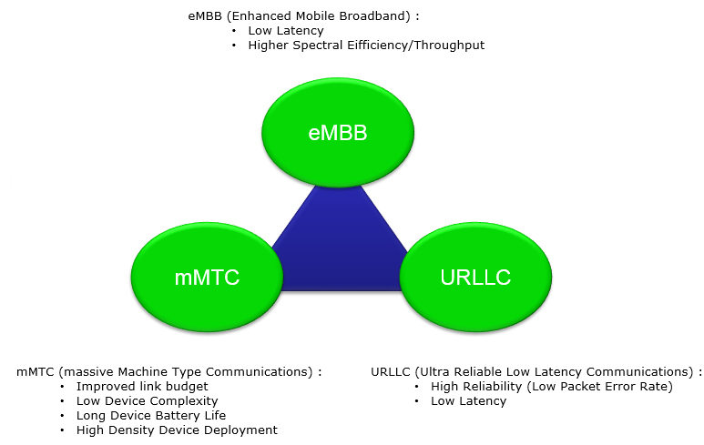
- support of multiplexing of different services (eMBB, mMTC, URLLC)
- support of user multiplexing according to basestation-to-UE uplink/downlink and UE-to-UE sidelink
- support of extreme physical properties, e.g, very wideband and narrow band, TDD and FDD, sub 6 Ghz and mmWave
- efficient use of channel reciprocity in TDD (using frequent sounding opportunities)
- support of dynamic TDD assignment with support for managing interference between source and destination pairs
- support of self-contained subframe which enables a transmission and ACK/NACK in the same subframe.
- support of self-contained subframe with a single interlace structure
- possible support of self-contained subframe with multiple interlace structure for forward compatibility and subject to overhead constraints for given target latency
- support for modes where a short intermediate round of communication between the source cnad destination can occur within a subframe
- support of tight coupling across aggregated carrier (i.e, supporting carrier aggregation)
Why Short Subframe ?
The main reason is pretty obvious. It is to meet such a short latency requirement in 5G. It is commonly agreed that the latency requirement would be only around 1 ms. In current LTE using 1 ms subframe, the latency in reality is in the range of several tens of ms and upto over 100 ms. So it can be easily guessed that the subframe length should be much shorter than 1 ms to meet the 1ms end-to-end radio latency requirement.
Then how short it should be ? How about 0.5 ms ? It may be OK if data transmission happens in a single step. But it may take several steps to complete a single data transfer as in the example below. If the single subframe length is 0.5 ms, it would be easily get over 1ms to complete the process.
i) UE -> NW : Scheduling Request
ii) UE <- NW : Grant
iii) UE -> NW : Data Transmission
iv) UE <- NW : ACK/NACK
There is another reason for short subframe length and this is more related to physical properties of 5G operating frequency. In case when OFDM operates in very high frequency like mmWave, it is very difficult to make it work in such a short subcarrier spacing like 15 Khz as we do in current LTE. Usually frequency drift (like doppler shift or drift due to poor local oscillator) happens in propotion to operating frequency. If we use the frequency like 26 Ghz, even a small fraction of frequency drift happens, it would get easily over several tens of Khz. Therefore, it is highly likely that 5G will use OFDM with much wider sub carrier spacing (meaning Wide Subcarrier) comparing to current LTE. If the subcarrier width gets wider, the symbol length gets shorter (this is based on inverse relationship between frequency domain and time domain). If we assume that we will pack the same number of symbols within a subframe, the shorter symbol length would create shorter subframe. (I hope I would not confuse you).
Factors determining Subframe Structure (Subcarrier Spacing, # of Subcarriers, # of Symbols etc)
When I was reading various documents about possible subframe structures for 5G, the first questions poping up my mind was 'where these strange numbers (e.g, xx Khz subframe structure, xx symbols in a subframe, xx subcarriers etc). I think I could make some guess, but was not sure exact technical background to determine these numbers. And I found some technical background for this from 3GPP TDoc R1-162204 ([7]) and R-162157([8]). Followings are the proposal from the document.
The specific values for each parameters about the subframe structure would be determined by the service types that will be supported in a specific situation. The major categories of service types and fundamental requirements for each service type are described as follows in R1-162204([7]).
Symbol Length/SubCarrier Spacing
As in other aspect of frame structure, there are many different ideas has been proposed on Symbol length and subcarrier spacing. In thise section, I will introduce you some of these ideas.
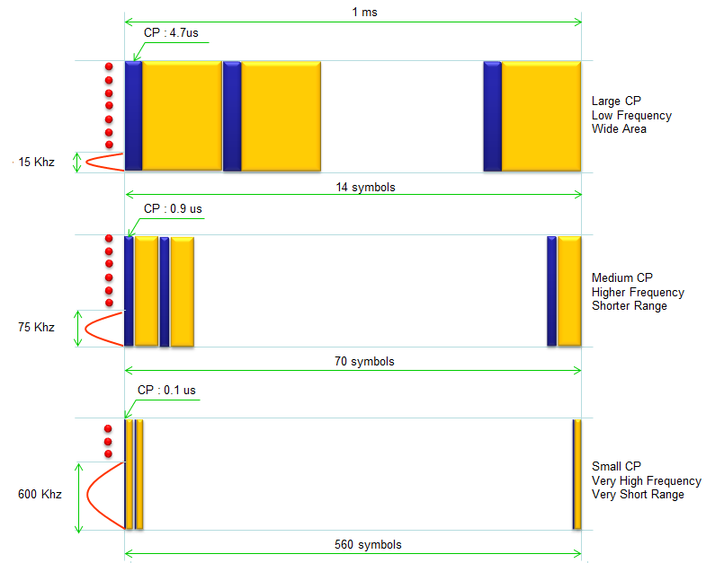
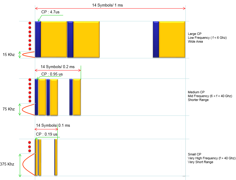
Example 1 >
Following illustration is based on data proposed in Ref [1]. This is designed with considersation of compatibility with current LTE. Three types of SubCarrier Spacing are shown here. The first one shows the subcarrier spacing and Symbol Length which is same as current LTE. The second one shows the subcarrier spacing gets 5 times wider than the current LTE and symbol length gets 5 times shorter comparing to the current LTE. The second one shows the subcarrier spacing gets 40 times wider than the current LTE and symbol length gets 40 times shorter comparing to the current LTE
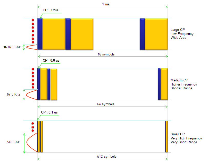
Example 2 >
Following illustration is based on data proposed in Ref [1]. This is new subframe design. For now, I am not sure what is the advantage of these subcarrier/symbol structure comparing to the structure shown above. General trend is understandable. The wider the subcarrier spacing is, the shorter the symbol length is. This is physical property. But I am not sure how they come up with this specific (rather strange) number. I will get this updated as I find/understand more.
Example 3 >
Followings are proposed by Huawei and HiSilicon in R1-162167 ([8]). As you see here, it is proposed to use different subcarrier spacing, different CP length and even different TTI (I am not sure if exact the same parameter value like 15 Khz, 1 ms TTI will be used in mmWave, Low Latency subframe, but I think overal structure/concept itself is applicable).
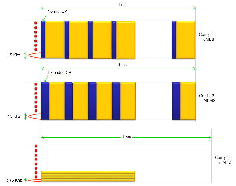
In real application, this proposal envison the possibility of using all these structure multiplexed together as illustrated below. (I think this kind of application is a main motivation of proposing a 5G waveform candidate called f-OFDM). Feasibility of this type of multiplexing is examined in R1-163224 ([10]).
Example 4 >
Followings are proposed by Intel in R1-162386 ([12]). Overall concept is similar to Example 1 and Example 2. I strongly recommend you to read this TDoc since it describes not only all these proposals but also pretty clear techical background for each of these proposals (options).
Subframe Structure - Control Channel and Reference Signal
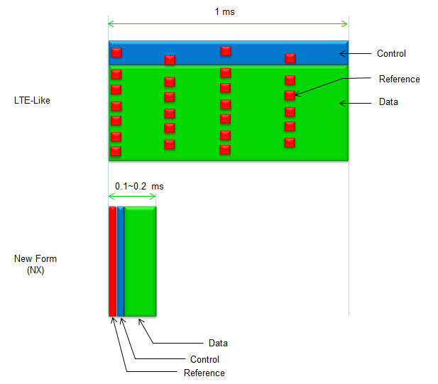
Now let's look into the Subframe Structure in terms of resource element allocation. For this one as well, I will start introducing the proposal from Ericsson (Ref [1]).
As illustrated below, there can be two major types suggested. One is the type which is more like current LTE/LTE-Advanced and the other type is for new waveform. In LTE-Like structure, the reference signal is distribute over both time and frequency domain. But in new subframe, the reference signal is distributed across frequency domain only. In terms of time domain, it takes only one or more consecutive symbols. This is understandable because the subframe length is very short we can assume that the channel condition would not vary (meaning coherent ) within a subframe.
Subframe Structure - Control and Data
In this section, I will keep accumulating the examples of subframe structure from various papers and whitepapers. Each one would have its own design concept. We don't know which type of subframe will be defined by 3GPP yet. But reviewing various types of proposal will give you a lot of insight with various aspects and help you understand 3GPP specification when it is released.
Example 1 >
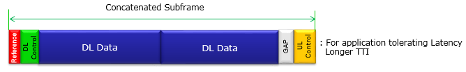
One interesting idea proposed by many players is the subframe structure in which both DL data and UL control (mainly for ACK/NACK for DL data) sits within the same subframe, so that DL transmission and corresponding ACK/NACK completes within the single TTI. It would be very challenging in Physical layer DSP or FPGA, but it think it would simplify the MAC layer HARQ process. You might have experience how much complicated (confusing) it become about HARQ process in LTE in TDD mode. I think this kind of subframe structure would clear up a lot of confusion.
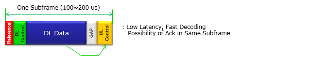
Depending on configuration, they can concatenate multiple DL subframe and add only one UL control in the last subframe. This would result in a little bit longer latency, but it would remove a lot of overhead and increase throughput in the situation where the latency is not so critical.
Example 2 >
Another example of the proposed frame structure (Ref [5]) is as follows. In this frame (subframe), you see both Tx Control and Rx Control so that they can transmit and receive the scheduling request and Grant with Synchronization signal in every frame. The frame length can be as short as 0.25 ms with subcarrier spacing of 60 Khz.
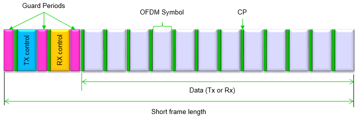
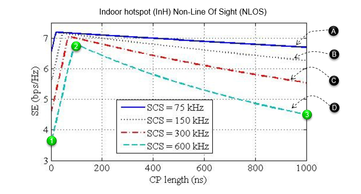
The details of each parameters (e.g, CP length, OFDM Symbol length, Subcarrier Spacing and Guard Periods) should be determined after further research. In most case, these parameters are in trade-off relationships so a lot of optimization research should be performed. (The section IV. LIMITS DUE TO THE OFDM FRAME LENGTH of Ref [5] would give you pretty good insight on how these parameters are inter-related). Followings are some of the plots from the reference showing the relationships among several parameters (CP Length, Subcarrier Spacing (SCS), Spectrum Efficiency(SE))
Let's first pick one trace and see what it means. I just picket the lowest trace (no special reason). I put a couple of number label (1), (2), (3). If you see the segment from (1)-(2), you see the spectrum efficiency gets better as CP length gets larger. But if you see the segment from (2)-(3), the spectrum efficiency gets worse as CP length gets larger. In the segment of (1)-(2), the effect of increasing robustness by the increasing CP length play dominant rolles and this is why the spectrum efficiency is increasing in the region. However, after it hits a peak (point (2)), the overhead caused by the increasing CP length is more dominant than the increased robustness. This is why the spectrum eifficiency is decreasing in the region.
Now let's compare among the four traces labelled as (A), (B), (C), (D). You see overal trend is similar meaning that Spectrum Efficiency is increasing to a certain point but start declining from the peak point. The differences among these traces are with SCS (Subcarrier Spacing). Trace (A) represents the case with the shortest SCS (75 Khz) and Trace (D) represents the case with the longest SCS (600 Khz). Trace (A) shows the higher spectrum efficiency than Trace (D). With the trends from (D) to (A), you may say the spectrum efficiency gets better as SCS gets shorter.
Then you may ask why they haven't tried even shorter SCS in this paper. It is not mentioned about the effect of even shorter SCS in this paper. I think it would still improve the spectrum efficiency if we get SCS a little bit shorter than that, but if we make it too short if the robustness of the communication gets worse due to weakness to phase noise. So too small SCS cannot be used in very high frequency.
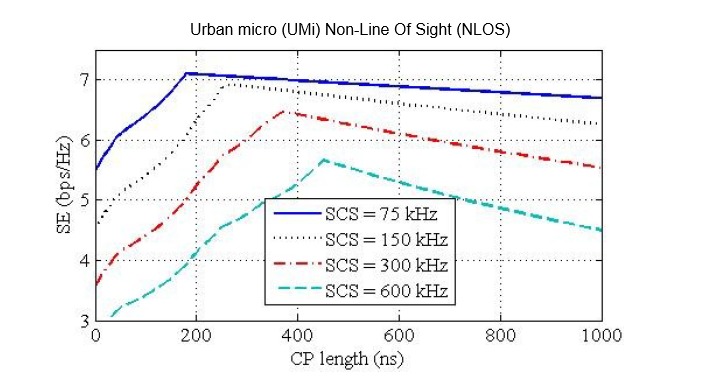
Following plot is the same experiement but in different environment from the previous one. The way you interpret the plot is exactly same as previous plot. Here, compare this plot to the previous plot. From this comparison, you would notice that Urban micro environment shows poorer spectrum efficiency than Indoor hotspot cases with the same CP and same SCS. We need to increase the CP length greatly to achieve the same spectrum efficiency as Indoor Hotspot case.
Example 3 >
Following is another example of subframe structure proposed in Ref [6] (I strongly recommend you to read this reference. You would get a lot of insight on various factors you need to consider when you design subframe structure).
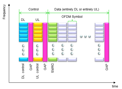
Following Table (5G Column) shows the detailed parameters about the subframe structure proposed in this paper. The above illustration is mappend to the '5G' columm. Other columns are presented here just for comparison. Some of the parameters are represented in the illustration but some of them are not in the illustration. So combine the illustration and the table in your brain to picture the complete details)
|
Parameters |
5G |
LTE |
LTE-A (5 CCs) |
802.11ac |
|
|
Carrier Bandwidth [Mhz] |
200 |
20 |
100 |
20 |
160 |
|
Subcarrier spacing [kHz] |
60 |
15 |
15 |
312.5 |
312.5 |
|
Symbol Length [us] |
16.67 |
66.67 |
66.67 |
4 |
4 |
|
FFT size |
4096 |
2048 |
5 x 2048 |
64 |
512 |
|
Effective subcarriers |
3300 |
1200 |
6000 |
56 |
484 |
|
TTI duration [ms] |
0.25 |
1 |
1 |
variable |
variable |
|
Number of GPs |
3 |
2 |
2 |
none |
none |
|
Number of symbols per frame |
14 |
14 |
14 |
n.a |
n.a |
|
CP duration [us] |
1 |
4.7 (short) |
4.7 (short) |
0.4 (short) |
0.4 (short) |
|
GAP duration [us] |
0.89 |
66.67 (min) |
66.67 (min) |
none |
none |
|
Overhead (CP+GAP) [%] |
6.67 |
7.25 |
7.25 |
11 |
11 |
|
HARQ Process |
4 |
up to 15 |
up to 75 |
none |
none |
Let's summarize the characteristics of this frame structure based on the description on the paper (I will try to express it in my own words).
Separation of Control channel and Data channel in Time Domain : As you see in the frame structure, Control channel and Data channel part is clearly separated. With this design, they can design the pipeline processing which is more cost effective. It means we can design separate independent processing module, one processing module is handling control channel only and the other processing module is handling data channel only. In this way, UE can process its dedicated control channel while (almost at the same time) it is tranmitting/recieving in the data parts. As a result, the latency can be decreased.
This design can be helpful in power saving as well because UE can completely turn off the transmitter or reciever if the control channel part does not have any scheduling information for transmission or reception.
Existance of DL and UL control channel in every frame : In this frame, both DL and UL control channel always exists in every frame (subframe). It means Network can send DL control information in any subframe and UE can send UL control information in any subframe. In this way, even in TDD type of communication you don't need such a complicated resource allocation and HARQ report scheme as you see in current TDD LTE (If you are not familiar with how complicated/confusing the current TDD LTE scheduling/reporting method is, see these links : TDD HARQ, TDD Reporting Mode)
UL only or DL only Data channe : The data channel part will be dedicated for DL only or UL only within the frame. Whether it will be DL only or UL only will be determined by the control channel. This would also help with power saving. If it is for DL only, the UE can completely turn off the transmitter during the data channel period. If it is for UL only, the UE can completely turn off the reciever during the data channel period.
DMRS (DeModulation Reference Signal) : The first symbol in data channel is dedicated for DMRS. Zadoff-chu sequence is used here because of its favorable cross-correlation properties.
Large Subcarrier Spacing : As you see in the table, the sub carrier spacing is 4 times larger than LTE/LTE-A subcarrier spacing. Due to this, the symbol length in this frame can be 4 times shorter than LTE/LTE-A symbol length. With this large subcarrier spacing, this waveform can be much more robust than LTE/LTE-A in terms of phase noise. As a result, we can implement this waveform at significantly higher frequency with relatively cheap device.
Reference
[1] 5G - key component of the Networked Society
RWS-150009 3GPP
RAN Workshop on 5G
Phoenix, AZ, USA, September 17 18, 2015
[2] METIS Deliverable D.2.4 Proposed Solution for New Radio Access
[3] Achieving low latency and energy consumption by 5G TDD mode optimization
Eeva Lhetkangas (1), Kari Pajukoski (1), Jaakko Vihril (1),
Gilberto Berardinelli (2), Mads Lauridsen (2), Esa Tiirola (1), Preben Mogensen (2,3)
(1) Nokia Solutions and Networks, Oulu, Finland
(2) Department of Electronic Systems, Aalborg University, Denmark
(3) Nokia Solutions and Networks, Aalborg, Denmark
[4] 5G small cell optimized radio design
Preben Mogensen (1, 2), Kari Pajukoski (3), Esa Tiirola (3), Eeva Lhetkangas (3), Jaakko Vihril (3),
Seppo Vesterinen (3),
Matti Laitila (3), Gilberto Berardinelli (2), Gustavo W. O. Da Costa (2), Luis G. U. Garcia (2),
Fernando M. L. Tavares (2), Andrea F. Cattoni (2)
(1) Nokia Siemens Networks, Aalborg, Denmark
(2) Department of Electronic Systems, Aalborg University, Denmark
(3) Nokia Siemens Networks, Oulu, Finland
[5] Achieving low latency and energy consumption by 5G TDD mode optimization
Eeva Lhetkangas (1), Kari Pajukoski (1), Jaakko Vihril (1), Gilberto Berardinelli (2), Mads Lauridsen (2), Esa Tiirola (1), Preben Mogensen (2,3)
(1) Nokia Solutions and Networks, Oulu, Finland
(2) Department of Electronic Systems, Aalborg University, Denmark
(3) Nokia Solutions and Networks, Aalborg, Denmark
[6] 5G small cell optimized radio design
Mogensen, Preben Elgaard; Pajukoski, Kari; Tiirola, Esa ; Lhetkangas, Eeva; Vihril, Jaakko; Vesterinen, Seppo; Laitila, Matti; Berardinelli, Gilberto; Da Costa, Gustavo Wagner Oliveira; Garcia, Luis Guilherme Uzeda; Tavares, Fernando Menezes Leito; Cattoni, Andrea Fabio
[7] 3GPP R1-162204. 3GPP TSG RAN WG1 Meeting #84bis - Numerology Requirement
[8] 3GPP R1-162167. 3GPP TSG RAN WG1 Meeting #84bis - Overview of 5G Framestructure
[9] 3GPP R1-162156. 3GPP TSG RAN WG1 Meeting #84bis - Scenario & design criteria on flexible numerologies
[10] 3GPP R1-163224. 3GPP TSG RAN WG1 Meeting #84bis - Feasibility of Mixing Numerology in an OFDM System
[11] 3GPP R1-162206. 3GPP TSG RAN WG1 Meeting #84bis - FrameStructure Requirements(click here for TDocs)
[12] 3GPP R1-162386. 3GPP TSG RAN WG1 Meeting #84bis - Numerology for new radio interface
<== Highly recommended (click here for TDocs)