PHY Processing
Physical Layer Processing is pretty complicated issues. Unlike other layers, it would be very difficult for you to understand the details clearly unless you have very strong academic (theoretical) background. Even when you have pretty strong background in a specific area of PHY layer, some other area of the PHY layer may look completely new to you. It applied to me and I am still in the precess of learning the details piece by piece.
Partly because of the nature of the technology and partly because of my poor organizing skill, this PHY layer process is scattered around multiple different pages and in some case the same topic is described in different pages with a little bit different angle. So sometimes even I have difficulties in finding proper information of PHY process in my own site :).
So I decided to create a kind of 'Contents' (or Index) pages of a book presenting the organization of the book in illustrated format and points the details in the form of hyperlink which are scattered across the whole site.
Followings are the topics I will talk about in this page.
Mathematical Background - Matrix, Matrix, Matrix
You don't have to see this section first if you are so allergic to mathematics. I am not making fun of you. I am also allergic to math :). But I strongly recommend you to come back here and see how much this make sense to you. Math itself is not so complicated. The math operation here is the one you might have learned in high school math or in the first or second year in university. As you see, you only have to know how to multiply matrices. The important thing is to understand 'Why we have to this kind of thing in this process ?' and 'what is the physical meaning of each of the matrix and meaning of the operation ?'. Actually finding/understanding the answers to these questions might be what you would learn in a Ph D course. However, you don't have to be a Ph D. Don't try to understand this at once and don't get disappointed even when this does not make sense to you when you first look at it. Try to read books, web pages, whitepapers as much as possible and you will gradually catch up the meaning.
Just as a conclusion, in LTE overall physical layer processing can be illustrated as shown below. The most important thing is to figure out what kind of matrix I have to use for each steps. The simple answer is 'create matrices in such that the rank of matrix product of the whole process become maximum value'.
Here, you would natuarally ask what is 'Rank' ?. Why we need to get max Rank ? For this, you would also need to do some math study. See Matrix : Rank page. At least, I tried to explain what is Rank and what is the meaning of max rank value.
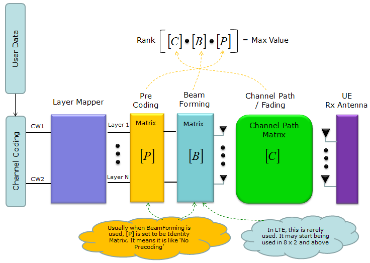
In real situation, the channel Matrix ([C]) is usually given because it is determined by the channel condition of the communication. We cannot change it as we like. So the only way of getting the max Rank (meaning best MIMO condition) is to change [P] or [B] to make the Rank of the path matrix is as close as possible to the max value. To do this, we need to know of the channel matrix [C]. But transmitter (eNB in LTE downlink case) is not able to know of [C], only receiver can evaluate [C] based on reference signal embedded in the recieved signal. So UE has to figure out what should be the best matrix for [P] or [B] and let transmitter (eNB) know of it. This is the purpose of PMI, RI report.
Now let's think of one example of a system using 4 x 2 MIMO. and I assume that Beamforming is not used in this example. In this case, we only have to consider the two matrix [P] and [Q].
For this system, we can think of two cases. First we can think of the situation where [C] is given and ask question saying "What is the best [P] matrix for the given [C] matrix ?
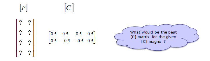
Next we can think of the situation where [P] is given and ask question saying "What is the best [C] matrix for the given [P] matrix ?
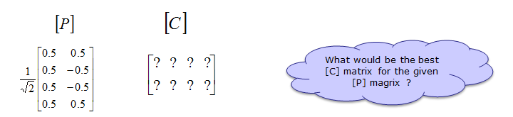
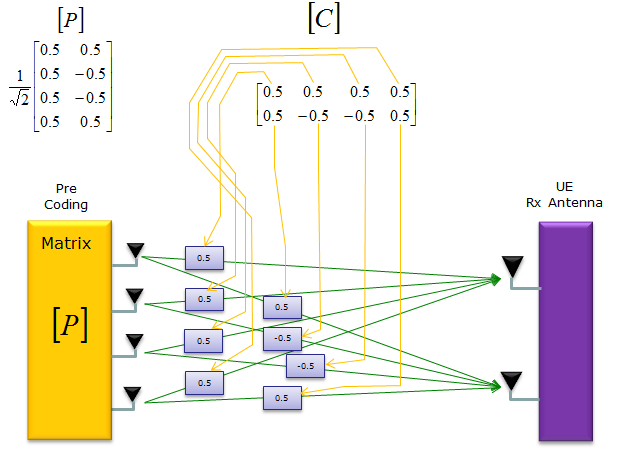
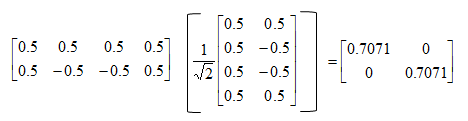
Without going into boring details of mathmatics, let me give you just the answer. If you create [P], [C] as shown below, that can be the best for each other. Of course, if you have different [C], you would need different [P]. (In LTE, various [P] matrix is defined in 3GPP specification and [C] is determined by the communication channel and is estimated (calculated) by UE)
You may ask how do I know the [P] and [Q] given above is the best combination ?
If you take the product of the two matrix (matrix inner product), you would have following result (If you are familiar with the concept of eigen value/eigen vector or SVD, you would intuitively see the result indicate two independent channel (two non-interfering path)). Also if you take the rank of the resulting matrix, it is 2 (max rank for 2 x 2 matrix). It meets the criteria of the best data path that I explained above.
2 x 1 Tx Diversity, 2 Layer, 1 Codeword
|
|
||||
|
(1) Coding |
(2) Layer Mapping |
(3) Precoding |
(4) Tx/Rx Path/Fading |
|

(1) Coding : This is process where user data (bit stream) go through channel coding process and converted to each codeword. DL-SCH coding process as an example, refer to "Channel Coding Processing for DL SCH/PCH/MCH"
(2) Layer Mapping : This is the process where each codeword is mapped to mapped to one or multiple layers. Refer to Layer Mapping page.
(3) Precoding : This is process where the layer data are allocated to multiple antenna ports (logical antenna ports in this stage). See the first section of Precoding page for details.
(4) Channel Path/Fading : you can get the general concept of Channel Path by refering to Channel Modeling page and refer to Fading page to understand how to derive channel correlation matrix.
NOTE :
The reason for 4x4 matrix for 2x1 Tx Diversity is based on following precoding matrix. You may refer to this page if you want to understand fundamental things about Tx Diversity. The conding method in the linked page is not exactly same as this matrix, but you would have some insight on how this precoding works.
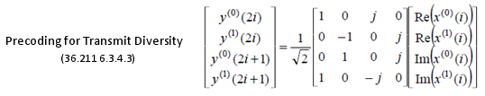
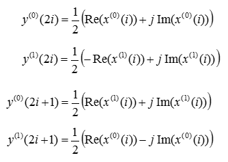
In many cases technical specification represents precoding in matrix form, but sometimes the matrix representation may not be easy for intuitive understanding. I know, for some people those matrix notation may look simpler and more intuitive. If a matrix represenation does not give you any practical understanding, I would suggest you to expend the matrix into ordinary equations as below and think of how the complex and real part of each input data (x()) get distributed into each of the Tx antenna at each transmission timing.
2 x 2 MIMO, 2 Layer, 2 Codeword
|
|
||||
|
(1) Coding |
(2) Layer Mapping |
(3) Precoding |
(4) Tx/Rx Path/Fading |
|
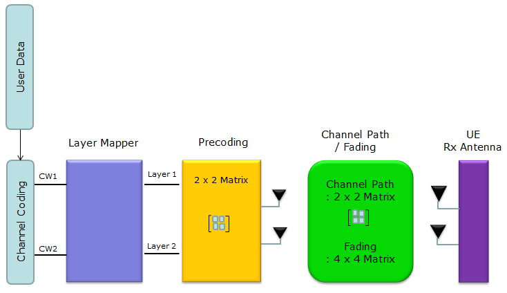
(1) Coding : This is process where user data (bit stream) go through channel coding process and converted to each codeword. DL-SCH coding process as an example, refer to "Channel Coding Processing for DL SCH/PCH/MCH"
(2) Layer Mapping : This is the process where each codeword is mapped to mapped to one or multiple layers. Refer to Layer Mapping page.
(3) Precoding : This is process where the layer data are allocated to multiple antenna ports (logical antenna ports in this stage). See the first section of Precoding page for details.
(4) Channel Path/Fading : you can get the general concept of Channel Path by refering to Channel Modeling page and refer to Fading page to understand how to derive channel correlation matrix.
Note : Since this is one of the simplest form of MIMO (the first steps of MIMO concept), I recommend you to go through MIMO page as well.
4 x 2 MIMO, 2 Layer, 2 Codeword
|
|
||||
|
(1) Coding |
(2) Layer Mapping |
(3) Precoding |
(4) Tx/Rx Path/Fading |
|
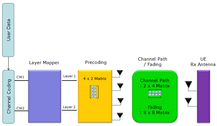
(1) Coding : This is process where user data (bit stream) go through channel coding process and converted to each codeword. DL-SCH coding process as an example, refer to "Channel Coding Processing for DL SCH/PCH/MCH"
(2) Layer Mapping : This is the process where each codeword is mapped to mapped to one or multiple layers. Refer to Layer Mapping page.
(3) Precoding : This is process where the layer data are allocated to multiple antenna ports (logical antenna ports in this stage). The specific Codebook for this configuration is in 4 x 2 MIMO Antenna section (If you are interested in how this codebook is derived, read the whole section of Codebook selection for Precoding - 4 Antenna Ports )
(4) Channel Path/Fading : you can get the general concept of Channel Path by refering to Channel Modeling page and refer to Fading page to understand how to derive channel correlation matrix.
Note : Since this is one of the simplest form of MIMO (the first steps of MIMO concept), I recommend you to go through MIMO page as well.
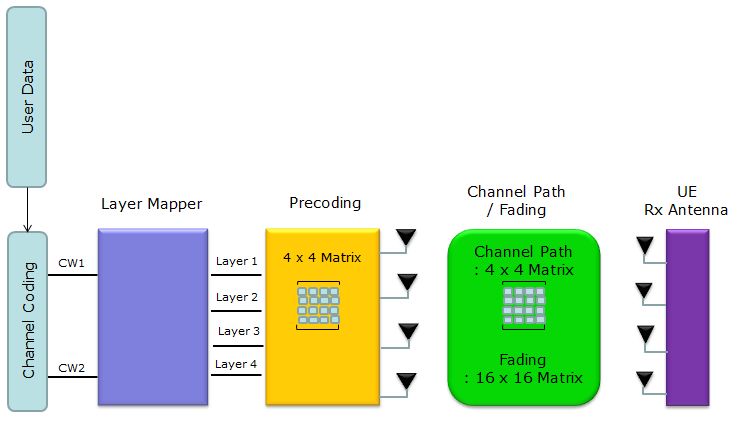
4 x 4 MIMO, 4 Layer, 2 Codeword
|
|
||||
|
(1) Coding |
(2) Layer Mapping |
(3) Precoding |
(4) Tx/Rx Path/Fading |
|
8 x 2 MIMO, 2 Layer, 2 Codeword
|
|
|||||
|
(1) Coding |
(2) Layer Mapping |
(3) Precoding |
(4)BeamForming |
(5) Tx/Rx Path/Fading |
|
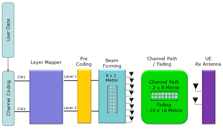
(1) Coding : This is process where user data (bit stream) go through channel coding process and converted to each codeword. DL-SCH coding process as an example, refer to "Channel Coding Processing for DL SCH/PCH/MCH"
(2) Layer Mapping : This is the process where each codeword is mapped to mapped to one or multiple layers. Refer to Layer Mapping page.
(3) Precoding : This is process where the layer data are allocated to multiple antenna ports (logical antenna ports in this stage). As of now, 8 x 2 is used only with TM9 (BeamForming). In this case, the procoding is done as described in Precoding for BeamForming . If you see the Precoding process, you would notice the process simply maps each layer to each antenna port(virtual port/UE specific antenna port). No matrix operation is performed in this process.
(4) In 8 x 2, TM 9 case. The matrix operation to map the two virtual antenna port to 8 physical happens in BeamForming process. Here 8 x 2 matrix is applied to the incoming two data stream to map the two stream onto 8 physical antenna. What is the contents of the 8 x 2 matrix ? 3GPP does not specify the contents of the matrix, it simply says "you can use randomly selected matrix". Therefore, in case of 8 x 2, TM9 case, Codebook is not used.. but in some equipment (probably in some live network as well) the codebook specified in 36.213 Table 7.2.4-2 can be used as the beamforming matrix.
If you want to have some CSI report from UE, you can combine CSI specific reference signal as illustrated in Mapping between Antenna port and physical antenna
(5) Channel Path/Fading : you can get the general concept of Channel Path by refering to Channel Modeling page and refer to Fading page to understand how to derive channel correlation matrix.
Note : Since this is one of the simplest form of MIMO (the first steps of MIMO concept), I recommend you to go through MIMO page as well.