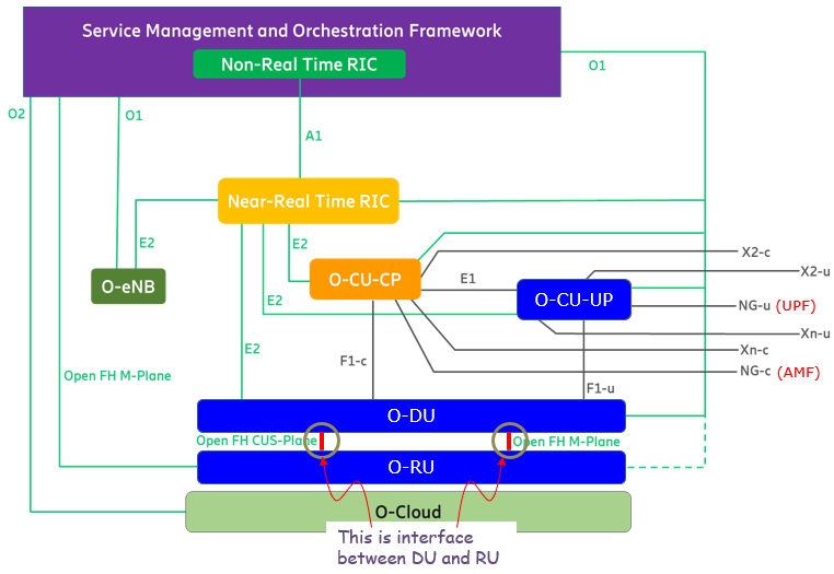
The FH (Fronthaul) interface, specifically the DU-RU interface, is a critical link in Open RAN architecture that connects the Distributed Unit (O-DU) to the Radio Unit (O-RU). It facilitates the transmission of control, management, and user data between these two components. The fronthaul is divided into different planes, including the Control and User Plane (CUS-Plane) and the Management Plane (M-Plane). The CUS-Plane carries real-time traffic, such as user data and control information required for radio signal processing, while the M-Plane is responsible for configuration, monitoring, and fault management. Open RAN standards define this interface to be open and interoperable, allowing operators to use equipment from multiple vendors. The FH interface supports protocols such as eCPRI and Open FH to ensure efficient data exchange and synchronization between the DU and RU, enabling flexible and scalable network deployments.
Followings are breakdown of this topic (i.e, DU-RU interface) :
Two Categories of the Interface ?
The most commonly adopted DU-RU interface in Open RAN is the 7.2x split, as defined by the O-RAN specification. This interface is categorized into two options: Category A (Cat A) and Category B (Cat B), which determine how processing responsibilities are divided between the Distributed Unit (DU) and the Radio Unit (RU). The key distinction between these categories lies in where the precoding function is performed. In Cat A, the DU performs precoding before sending the data to the RU, meaning that the beamforming weights are applied at the DU. The RU then handles digital beamforming, inverse fast Fourier transform (IFFT), cyclic prefix (CP) addition, and digital-to-analog conversion. This approach allows centralized beamforming control but requires higher fronthaul bandwidth. In Cat B, the DU sends unprecoded IQ data to the RU, where the precoding is applied before digital beamforming and other radio processing functions. This reduces fronthaul bandwidth requirements but shifts computational complexity to the RU. Both configurations impact fronthaul efficiency, processing load distribution, and the overall flexibility of Open RAN deployments, allowing operators to optimize network performance based on their specific ne
< based on O-RAN.WG4.CUS.0-R003-v15.00 : Figure 4.2-1 >
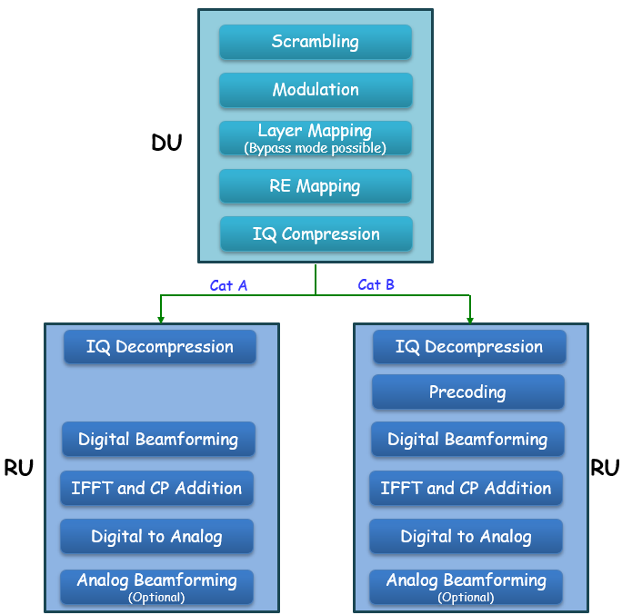
Saying again, Cat A places most Layer 1 (L1) processing, including precoding, in the DU, while Cat B shifts precoding and beamforming responsibilities to the RU. Cat B is typically used for Massive MIMO (M-MIMO) deployments, where RU processing helps reduce fronthaul bandwidth requirements. Followings are breakdown and dsecriptions of the two options
Category A (Cat A) - Processing Split: DU performs precoding, RU mainly handles RF functions.
- Use Case: Suitable for small-scale deployments, up to 8 digital antenna ports.
- Advantage: Centralized control allows for flexible coordination and network-wide optimizations.
- Limitation: Requires more fronthaul capacity, making it less efficient for high-density MIMO setups.
Category B (Cat B) - Processing Split: RU performs precoding and beamforming, DU handles high-PHY and MAC functions.
- Use Case: Ideal for M-MIMO (more than 8 antenna ports) and high-density urban deployments.
- Advantage: Less fronthaul bandwidth is needed, and real-time beamforming improves efficiency.
- Limitation: Distributes processing to RU, increasing its complexity and cost.
Challenges with Beamforming on RU
In Open RAN architectures, particularly under the Category B (Cat B) functional split, beamforming is managed within the Radio Unit (RU). While this approach reduces fronthaul bandwidth requirements, it introduces significant challenges that can impact network performance, especially in dense urban environments with high mobility and interference.
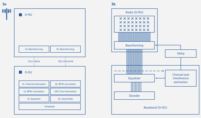
Image Source : Driving Open RAN forward
Key Challenges of Beamforming in the RU:
Loss of Channel Information : Implementing beamforming in the RU necessitates the reduction of data streams received from the DU This reduction leads to a loss of detailed channel information in both spatial and frequency domains, impairing the system's ability to accurately track channels and effectively suppress interference. - Why is Channel Information Lost?
- Since the DU does not handle beamforming, it does not generate beamforming weights based on real-time channel state information (CSI).
- The DU only sends a reduced set of IQ data streams to the RU instead of transmitting full per-layer data with detailed channel estimates.
- As a result, the DU loses access to the detailed spatial and frequency-domain CSI that would otherwise help optimize scheduling, interference management, and network-wide coordination.
- Impact of This Loss
- Less Accurate Beamforming – Because the DU no longer has full CSI, it cannot compute optimal beamforming weights. Instead, the RU applies pre-configured or estimated weights locally, which may be less accurate.
- Weaker Interference Suppression – Without complete CSI at the DU, it becomes difficult to coordinate interference mitigation strategies across multiple cells.
- Limited Scheduling Optimization – Since the DU has less visibility into real-time channel conditions, it cannot make the most efficient resource allocation decisions.
Processing Delays : Beamforming decisions in the RU are based on channel information previously calculated by the DU, introducing delays of approximately 10-20 milliseconds. Putting it in other words, the places for channel estimation and application of the estimation result are different and it takes some time for the channel estimation result to get transferred to the place where it is used. Such latency can degrade the system's responsiveness to rapid changes in the radio environment, affecting performance in scenarios with high user mobility and dynamic interference patterns.
Impact on Network Performance:
These challenges can lead to suboptimal beamforming, resulting in reduced user throughput and diminished spectral efficiency. In high-density deployments, such as stadiums or urban centers, the inability to promptly adapt to changing conditions can severely affect the user experience.
Need for a New Interface Beyond Cat A and Cat B?
Yes, the industry needed a new interface beyond Cat A and Cat B, leading to the standardization of Cat-B ULPI-A and Cat-B ULPI-B. These enhancements address uplink performance challenges in Massive MIMO, optimize fronthaul utilization, and ensure better interoperability between vendors. While Cat A remains viable for some scenarios, and standard Cat B is still used, Cat-B ULPI is now the preferred approach for high-performance Open RAN deployments.
The limitations of Category B (Cat B) in the Massive MIMO uplink scenario led to the realization that the existing 7.2x split was insufficient for optimal performance. Multiple simulations from different companies highlighted uplink performance degradation in Cat B, prompting the O-RAN Alliance to initiate a Work Item (WI) in February 2022. The objective was to determine whether these performance challenges justified a new architectural approach. The conclusion was clear: Cat B alone was not sufficient, necessitating the development of enhanced versions referred to as Cat-B ULPI-A and Cat-B ULPI-B.
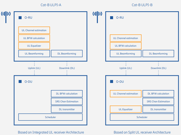
Image Source : Driving Open RAN forward
Introduction of Cat-B ULPI (Uplink Performance Improvement)
To address the shortcomings of Cat B, two enhanced versions—Cat-B ULPI-A and Cat-B ULPI-B—were proposed to improve uplink performance while maintaining interoperability.
Cat-B ULPI-A - Equalizer function placed in the RU
- Reduces fronthaul bitrate by transmitting only user data layers between RU and DU
- Maintains a clear separation of responsibilities between O-RU and O-DU
- Enables multi-vendor interoperability as RU and DU functions are well-defined
- Improves uplink spectral efficiency, allowing better utilization of fronthaul resources
Cat-B ULPI-B - Equalizer function placed in the DU
- Channel estimation must be performed in both O-RU and O-DU, requiring precise synchronization
- More challenging for multi-vendor interoperability, as different vendors may implement channel estimation differently
- Can potentially allow more centralized processing but at the cost of increased fronthaul bitrate
Why Was a New Interface Needed?
The standard Cat B split suffered from uplink inefficiencies, especially in high-density Massive MIMO deployments. The introduction of Cat-B ULPI was necessary because:
- Standard Cat B required 12 streams, while Cat-B ULPI only required 1-4 streams for the same uplink throughput.
- Cat-B ULPI-A significantly reduced fronthaul bitrate, making it more feasible for real-world Open RAN deployments.
- The standardization of both ULPI-A and ULPI-B ensures compatibility, allowing O-DU vendors to support both configurations, improving deployment flexibility.
Components of DU-RU Interface
The protocol used for the DU-RU interface in Open RAN follows a structured approach to ensure efficient data transmission, control, and synchronization. At the core of this interface is eCPRI, a transport protocol that carries IQ data between the Distributed Unit (DU) and the Radio Unit (RU). Unlike older CPRI technology, eCPRI is designed to work over Ethernet and IP networks, making it more flexible and efficient in managing bandwidth. To handle communication between the DU and RU, Open RAN uses the CUS-Plane protocol, which separates the control and user data, allowing better coordination of signal processing and beamforming. Additionally, the M-Plane protocol is responsible for configuring and managing the RU, ensuring smooth operation and remote control. Since precise timing is critical in mobile networks, synchronization is achieved using Precision Time Protocol (PTP) and Synchronous Ethernet (SyncE), which help align the timing of signals between DU and RU. These protocols operate over Ethernet and IP-based networks, ensuring seamless connectivity while reducing latency. By using these standardized protocols, Open RAN enables interoperability between different vendors, optimizes network performance, and provides a scalable solution for modern mobile networks.
eCPRI (Enhanced Common Public Radio Interface)
- Used for: Transporting IQ data between DU and RU
- Why eCPRI?
- Reduces fronthaul bandwidth compared to legacy CPRI
- Supports packet-based transport (Ethernet/IP) rather than time-division multiplexing (TDM)
- Allows statistical multiplexing and more efficient data transport
O-RAN CUS-Plane (Control & User Plane) Protocol
- Used for: Defining fronthaul communication between O-DU and O-RU
- CUS-Plane Breakdown:
- Control Plane (C-Plane) → Manages beamforming weights, timing, and scheduling.
- User Plane (U-Plane) → Transfers user data (IQ data) over eCPRI.
O-RAN M-Plane (Management Plane) Protocol
- Used for: Configuring and managing the O-RU remotely
- Protocol Stack: Typically based on NETCONF/YANG for network management
- Functions:
- O-RU software updates
- Performance monitoring
- Fault management
- Parameter configuration
PTP (Precision Time Protocol - IEEE 1588) & SyncE (Synchronous Ethernet)
- Used for: Synchronizing the DU and RU in time-sensitive operations
- Why Needed?
- Ensures tight timing synchronization between O-DU and O-RU for accurate beamforming and scheduling.
- Required for TDD (Time-Division Duplexing) synchronization in 5G deployments.
- PTP vs. SyncE:
- PTP (IEEE 1588v2): Packet-based time synchronization
- SyncE: Uses Ethernet signals for frequency synchronization
Transport Protocols (Ethernet, UDP/IP)
- Ethernet/IP-based Transport → eCPRI packets are encapsulated over UDP/IP and sent via Ethernet.
- Why not TCP? → UDP is used for low-latency, real-time packet transport (e.g., IQ data).
- Fronthaul Transport Options:
- Ethernet-based transport (preferred)
- MPLS (Multi-Protocol Label Switching)
- Optical transport networks (DWDM)
Timing Synchronization
Timing synchronization in the context of Open RAN (O-RAN) and 5G infrastructure is a critical process that ensures precise alignment of clocks between Distributed Units (DUs) and Radio Units (RUs) across various deployment models, including Cloud RAN (C-RAN), Centralized RAN (C-RAN), and Distributed RAN (D-RAN). At its core, timing synchronization involves coordinating the transmission and reception of signals with sub-microsecond accuracy using protocols like Precision Time Protocol (PTP), enabling seamless communication in time-sensitive applications such as carrier aggregation, beamforming, and time-division duplexing (TDD) that are fundamental to 5G performance. Its importance cannot be overstated, as even slight timing mismatches can lead to signal interference, degraded network reliability, and reduced quality of service, particularly as 5G networks demand higher spectrum frequencies and denser base station deployments, driving significant infrastructure investments. Implementing effective timing synchronization requires careful consideration of multiple factors: the network architecture (e.g., fronthaul reliability, cloud virtualization, or local timing sources), environmental challenges (e.g., temperature extremes in outdoor settings or controlled data centers), hardware capabilities (e.g., support for PTP masters, GNSS receivers, or accelerators like Intel’s FlexRAN), and the specific synchronization model (LLS-C1 to LLS-C4) chosen to balance simplicity, scalability, and autonomy across diverse deployment scenarios
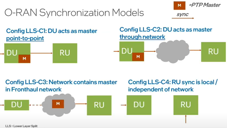
Image Source : Building an OpenRAN DU with Intel’s FlexRAN
Types of Synchronization Models
There are 4 different types of synchronization models namely LLS-C1 to LLS-C4 configurations, which are described below:
LLS-C1 (DU as Boundary Clock) : In LLS-C1, the DU acts as a boundary clock, receiving synchronization from the mid-haul or backhaul link and passing it directly to the RU. This aligns with the point-to-point setup in the diagram, where the DU (with the PTP Master) synchronizes the RU without network intermediaries. The session suggests that LLS-C1 is gaining traction in deployments, possibly due to its simplicity and reduced dependency on network infrastructure.- Setup: The DU receives synchronization from the mid-haul or backhaul link and acts as a boundary clock, directly passing timing to the RU in a point-to-point configuration.
- How It Works: The DU relays PTP signals to the RU without network intermediaries, ensuring precise timing for the RU’s time-sensitive operations.
- Implication: Gaining popularity due to its simplicity, LLS-C1 is ideal for Distributed RAN (D-RAN) deployments where direct DU-RU connections are feasible, such as in outdoor or rural cell sites. It requires the DU to have robust timing capabilities, supported by hardware like Intel CPUs and GNSS receivers. This model is less common in Cloud RAN or Centralized RAN, where fronthaul networks often handle timing centrally.
LLS-C2 (DU as Boundary Clock with Network) : In LLS-C2, the DU still acts as a boundary clock, but synchronization passes through the fronthaul network, including switches or routers. It emphasizes the need for synchronous Ethernet in these intermediate devices to maintain timing accuracy. This adds a layer of complexity compared to LLS-C1, as network equipment must support PTP or similar protocols to avoid jitter or latency issues.- Setup: The DU acts as a boundary clock, but synchronization passes through the fronthaul network, including switches or routers.
- How It Works: The DU receives timing from the mid-haul/backhaul and forwards it via the network to the RU, with synchronous Ethernet in intermediate devices ensuring accuracy.
- Implication: Suitable for larger networks, LLS-C2 introduces complexity due to potential network-induced jitter, requiring PTP-aware switches. It’s a flexible option for both Centralized RAN (C-RAN) and Distributed RAN (D-RAN) with networked fronthaul, though it may be less optimized for Cloud RAN, where virtualized timing sources in the cloud could simplify the process.
LLS-C3 (Network as Master) : In LLS-C3, the fronthaul network contains a timing master (e.g., via GNSS or a gateway), relieving the DU of the critical timing path to the RU. This configuration was common in early deployments, as noted, and is useful in centralized RAN (C-RAN) setups where the fronthaul network can be tightly controlled. The diagram’s cloud representation of the network aligns with this decentralized timing source.- Setup: The fronthaul network hosts a PTP Master (e.g., via GNSS or a gateway), synchronizing both the DU and RU.
- How It Works: Timing is managed by the network, bypassing the DU as the critical path, which aligns with Split 7.2 where the RU handles FFT/IFFT and the DU processes MAC/RLC layers.
- Implication: Common in early deployments, LLS-C3 is ideal for Centralized RAN (C-RAN) in controlled environments (e.g., data centers) and Cloud RAN (C-RAN), where virtualized DUs in a cloud environment rely on a centralized fronthaul timing master. This reduces the DU’s timing burden and leverages the controlled data center or edge cloud infrastructure, supported by open hardware platforms like Supermicro’s servers with Intel CPUs.
LLS-C4 (RU Local Sync) : In LLS-C4, the RU synchronizes independently, often using a GNSS antenna. This is particularly relevant for distributed RAN (D-RAN) deployments in remote or outdoor environments where network reliability might be an issue. The session’s discussion of environmental challenges (e.g., rural deployments in IP65 boxes) supports the practicality of this approach.- Setup: The RU synchronizes locally, often via a GNSS antenna, independent of the DU or network.
- How It Works: The RU uses its own timing source, while the DU may sync via the network, supporting Split 7.2’s distributed processing.
- Implication: Best for Distributed RAN (D-RAN) in remote or outdoor settings (e.g., IP65 boxes in rural areas), LLS-C4 offers autonomy but risks timing misalignment between DU and RU. This model is less relevant for Cloud RAN or Centralized RAN, where centralized or network-based synchronization is preferred.
Integration with 5G Infrastructure and Deployment Models
Let's think of a broader context for these synchronization models by contrasting different RAN deployment approaches: Cloud RAN (C-RAN), Centralized RAN (C-RAN), and Distributed RAN (D-RAN). These models reflect varying degrees of centralization and virtualization, influencing how synchronization is implemented using the LLS-C1 to LLS-C4 configurations.
The high investment in RAN (over 80% of capex, potentially increasing with 5G due to higher spectrum frequencies requiring more base stations) underscores the importance of optimizing synchronization across these deployment models. The move to open hardware platforms (e.g., Supermicro’s optimized servers with Intel CPUs and acceleration cards) supports all three configurations by providing flexibility, scalability, and the computational power needed for virtualized or distributed processing. Cloud RAN, in particular, benefits from this openness, enabling operators to dynamically allocate resources and integrate with cloud-native applications, while C-RAN and D-RAN leverage it for centralized and localized efficiency, respectively.
Cloud RAN (C-RAN) : Cloud RAN takes the concept of Centralized RAN a step further by fully virtualizing and centralizing the RAN functions (CU, DU, and sometimes parts of the RU processing) in a cloud-based environment, typically hosted in a data center or edge cloud. This leverages cloud-native technologies (e.g., Kubernetes, NFVI) to provide scalability and flexibility. Synchronization in C-RAN often aligns with LLS-C3, where the fronthaul network hosts a PTP Master (e.g., via GNSS or a network timing source), ensuring precise timing across virtualized DUs and RUs. The controlled data center environment, with regulated temperature and protection from dust or water, supports this setup. The use of open hardware platforms (e.g., Supermicro’s servers with Intel CPUs and acceleration cards) enhances C-RAN’s ability to handle the computational demands of virtualization while maintaining synchronization accuracy.Centralized RAN (C-RAN) : In traditional C-RAN, the CU and DU are co-located in a central office or data center, with the RU deployed at the cell site. This setup is also well-suited for LLS-C3, where the fronthaul network acts as the PTP Master, providing timing to both the DU and RU. The proximity of CU and DU reduces latency in the mid-haul, and the controlled environment minimizes environmental challenges. This configuration is ideal for urban deployments where centralized processing can optimize resource utilization, supported by the session’s emphasis on open hardware for scalability.Distributed RAN (D-RAN) : In D-RAN, the DU is distributed to the cell site, closer to the RU, reducing data traffic over the fronthaul link. This model is suited for LLS-C1 or LLS-C4. In LLS-C1, the DU acts as a boundary clock, receiving synchronization from the mid-haul or backhaul and passing it directly to the RU, making it practical for direct connections in outdoor or rural settings. In LLS-C4, the RU relies on local synchronization (e.g., GNSS), offering autonomy in remote deployments. The session notes that DUs in D-RAN must support extended temperature ranges (e.g., -20°C to 55°C) and be housed in rugged enclosures like IP65 boxes, addressing the environmental challenges of outdoor cell sites.
Challenges and Considerations
The challenges of implementing timing synchronization in Open RAN (O-RAN) and 5G infrastructure are multifaceted, requiring a nuanced approach to ensure seamless performance across diverse deployment models such as Cloud RAN (C-RAN), Centralized RAN (C-RAN), and Distributed RAN (D-RAN). These challenges stem from the critical need to maintain sub-microsecond accuracy in signal alignment, which is complicated by network reliability issues that can introduce jitter, latency, or packet loss etc
Network Reliability : Network reliability poses significant challenges for LLS-C2 and LLS-C3 configurations, where timing synchronization relies on the fronthaul network to relay PTP signals through switches and routers. This dependency is a critical factor in Cloud RAN (C-RAN) and Centralized RAN (C-RAN), where the fronthaul network serves as the backbone for delivering precise timing from a centralized PTP Master, such as a GNSS-based source or gateway. Any network-induced jitter, latency, or packet loss can disrupt synchronization accuracy, necessitating the deployment of PTP-aware infrastructure—such as switches and routers with synchronous Ethernet or boundary clock capabilities—to mitigate these issues. This requirement adds complexity and cost, particularly in large-scale or virtualized environments like Cloud RAN, where the fronthaul must support the dynamic allocation of resources across multiple virtualized DUs and RUs.Local Synchronization : Local synchronization as in the LLS-C4 configuration introduces its own set of challenges, as the RU relies on an independent timing source, such as a GNSS antenna, which may lead to timing drift over time due to variations in satellite signal quality or local oscillator stability. This issue is particularly pronounced in Distributed RAN (D-RAN) deployments, where RUs are often located in remote or outdoor settings, requiring careful coordination to align the RU’s timing with the DU’s network-synchronized clock to avoid performance degradation in time-sensitive 5G features like coordinated multipoint (CoMP). However, this concern is less relevant for Cloud RAN or Centralized RAN, where centralized or network-based timing masters provide a more consistent reference, reducing the risk of drift but shifting the burden to fronthaul network robustness.Hardware Considerations : Hardware considerations are equally vital and vary by deployment model. In Distributed RAN, the hardware—such as Intel CPUs, FPGAs, or acceleration cards—must support extended temperature ranges (e.g., -20°C to 55°C) and integrate GNSS receivers to ensure reliable local synchronization in harsh outdoor environments, often requiring rugged enclosures like IP65 boxes to protect against dust, water, and extreme weather. Conversely, Cloud RAN benefits from high-performance servers in controlled data center or edge cloud settings, where temperature regulation and stable power supplies allow for optimized processing of virtualized RAN functions without the need for ruggedized hardware. Across all models, the hardware must also support advanced features like FlexRAN offloading to handle the computational demands of Layer 1 processing, while ensuring compatibility with open hardware platforms to meet the scalability and interoperability goals of the O-RAN ecosystem. Balancing these hardware requirements with network and environmental factors is essential to achieving robust and efficient timing synchronization tailored to each deployment’s unique constraints.
Data Flow between RU and DU
The fronthaul data flow between the O-DU (Open Distributed Unit) and O-RU (Open Radio Unit) forms the backbone of the O-RAN architecture, enabling seamless communication in modern 5G networks through the 7.2x split of the Physical Layer. This interface, predominantly implemented using the eCPRI protocol, facilitates the exchange of critical data across multiple planes, including the User Plane for IQ samples, the Control Plane for scheduling and beamforming commands, the Synchronization-Plane for precise timing alignment, and the Management Plane for configuration and optimization. Defined by the O-RAN specification, the fronthaul supports a variety of data flows, such as downlink and uplink IQ data in the FFT frequency domain, PRACH IQ data, and LAA-related control messages, all tailored to meet the high-bandwidth, low-latency demands of 5G while accommodating flexible split options like Cat A and Cat B to balance processing loads between the O-DU and O-RU.
Type of the Data Flow
There are various types of data flow between DU and RU. Those types and detailed requirement is specified by O-RAN specification as illustrated below.
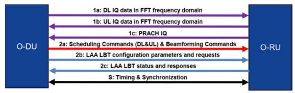
Image Source : O-RAN Front Haul Sample Application in Smart Edge Open
The high level summary of each type of data flow are as follows :
The U-Plane carries IQ (In-phase and Quadrature) data between the O-DU and O-RU, transmitted symbol by symbol within U-Plane messages. This data is critical for real-time signal processing.
- Data Flow 1a: Flows of IQ Data in FFT Frequency Domain on DL
- Direction: O-DU → O-RU
- Description: The O-DU sends compressed IQ samples in the frequency domain (post-FFT) for downlink transmission. This aligns with the first diagram’s “1a: DL IQ Data in FFT Frequency Domain.”
- Interface Role: The fronthaul transports these U-Plane packets, with compression reducing bandwidth demands.
- Data Flow 1b: Flows of IQ Data in FFT Frequency Domain on UL
- Direction: O-RU → O-DU
- Description: The O-RU sends uplink IQ samples in the frequency domain (post-FFT) to the O-DU. This corresponds to the first diagram’s “1b: UL IQ Data in FFT Frequency Domain.”
- Interface Role: The fronthaul carries these U-Plane packets back to the O-DU, where IQ decompression occurs
- Data Flow 1c: Flow of PRACH IQ Data in FFT Frequency Domain
- Direction: O-RU → O-DU
- Description: The O-RU sends IQ data from the Physical Random Access Channel (PRACH) in the frequency domain, used for initial UE access.
- Interface Role: This is an additional U-Plane flow, distinct from regular UL data, and is transported as part of the first diagram’s “PRACH IQ” under control messages.
- Interface Characteristics for U-Plane:
- Bandwidth: 10-25 Gbps for a 100 MHz 5G channel with 64 antennas, varying with compression efficiency.
- Latency: <100 µs one-way to support real-time 5G symbol processing.
- Compression: The second diagram highlights IQ compression/decompression, using techniques like quantization to optimize fronthaul usage.
The C-Plane transmits data control information required for processing U-Plane data, sent every slot (or Transmission Time Interval, TTI, in LTE) with headers and encapsulated payloads. C-Plane messages provide information about the next expected U-Plane packets.
- Data Flow 2a: Scheduling Commands (DL and UL) & Beamforming Commands
- Direction: O-DU → O-RU
- Description: The O-DU sends scheduling instructions (e.g., resource block allocation) and beamforming commands (e.g., weights for digital beamforming), as shown in the first diagram’s “2a: Scheduling Commands (DL&UL) & Beamforming Commands.”
- Interface Role: These are carried via eCPRI C-Plane messages (e.g., message type 2), ensuring real-time coordination.
- Data Flow 2b: LAA Listen-Before-Talk (LBT) Configuration Commands and Requests
- Direction: O-DU → O-RU
- Description: Commands and requests related to Licensed Assisted Access (LAA) LBT, a mechanism to avoid interference in unlicensed spectrum.
- Interface Role: Transmitted as C-Plane messages, aligning with the first diagram’s “LAAT Configuration Parameters and Requests” (LAAT encompassing LBT in this context).
- Data Flow 2c: LAA LBT Status and Response Messages
- Direction: O-RU → O-DU
- Description: The O-RU sends status updates or responses regarding LBT operations.
- Interface Role: Also part of the C-Plane, providing feedback to the O-DU for dynamic spectrum management.
- Interface Characteristics for C-Plane:
- Bandwidth: Low compared to U-Plane, but highly reliable delivery is critical.
- Frequency: Sent per slot (e.g., 0.5 ms for 30 kHz subcarrier spacing), requiring low latency.
- Structure: Encapsulated payloads with headers, as per eCPRI standards.
- Description: Ensures precise timing alignment between O-DU and O-RU for TDD and Massive MIMO operations, using IEEE 1588 PTP or SyncE.
- Interface Role: Bidirectional timing messages (first diagram’s “Timing & Synchronization”) are embedded in the fronthaul, with a requirement of ±1.5 µs time alignment error.
- Responsibilities: The O-RAN specification includes M-Plane for configuration and management tasks, such as:
- Generic static O-RU configuration.
- O-RU management (e.g., fault monitoring).
- Compression configuration (adjusting IQ compression parameters).
- Choosing a power-saving setting (e.g., enabling sleep modes).
- Interface Role: M-Plane messages are sent over the fronthaul to configure the O-RU and optimize performance, typically using eCPRI M-Plane protocols.
Sequence Diagram of the Data Flow
The high-level sequence of data flow across the fronthaul interface unfolds as follows: a Control Plane (C-Plane) message is transmitted first, providing the necessary instructions for the subsequent User Plane (U-Plane) message, which carries the IQ data for symbol transmission. A single C-Plane message can efficiently govern one or multiple consecutive U-Plane symbols, optimizing the coordination between the O-DU and O-RU in an O-RAN architecture. This design allows for flexibility in managing symbol processing, ensuring that the O-RU receives timely control information ahead of the IQ data, with a built-in margin to account for timing inaccuracies, thereby enhancing reliability and supporting the real-time demands of 5G communications.
One example sequence of data flow for DL C-Plane/U-Plane is illustrated as below.
< O-RAN.WG4.CUS.0-R003-v15.00 - 7.2.1>
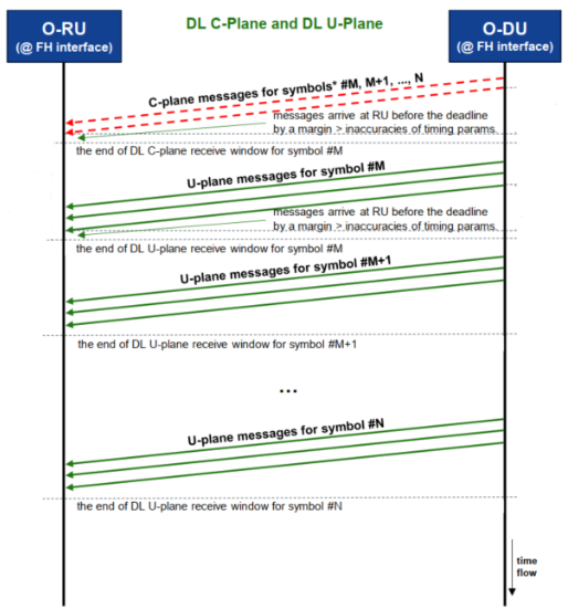
Breakdown and description of this sample flow is summarized as bellow :
- Step i) The process starts with the O-DU sending a single C-Plane message for symbols #M to #N to the O-RU over the fronthaul interface
- Step ii) This C-Plane message arrives at the O-RU before a specified deadline, with a margin included prior to the deadline to account for potential timing inaccuracies in its arrival, providing control instructions for all the subsequent U-Plane symbols within this range.
- Step iii)Following the C-Plane message, the O-DU begins transmitting the U-Plane message for symbol #M which carries the IQ data and the symbol is expected to be received by RU within the "end of DL U-Plane receive window" for symbol #M.
- Step iv) Next, the O-DU sends the U-Plane message for symbol #M+1, which is received by RU within its own "end of DL U-Plane receive window," governed by the initial C-Plane message.
- Step v) This pattern continues as the O-DU transmits U-Plane messages for symbols #M+2 up to #N, each received within their respective "end of DL U-Plane receive window," all under the control of the single preceding C-Plane message.
One example sequence of data flow for UL C-Plane/U-Plane is illustrated as below.
< O-RAN.WG4.CUS.0-R003-v15.00 - 7.2.1>
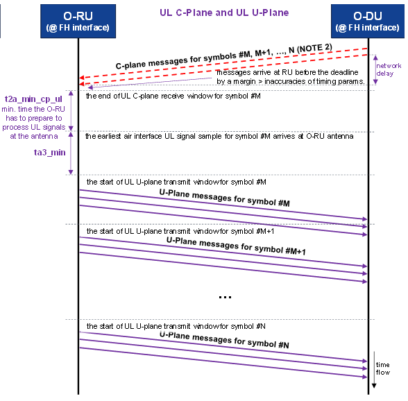
Breakdown and description of this sample flow is summarized as bellow :
- Step i) : The process begins with the O-DU initiating the uplink (UL) fronthaul data flow by sending a C-Plane message for symbols #M to #N to the O-RU over the fronthaul interface, depicted as a red dashed line on the timeline, which flows from left to right.
- Step ii) : This C-Plane message arrives at the O-RU before a specified deadline, with a margin included prior to the deadline to account for potential timing inaccuracies, providing control instructions for the O-RU to prepare for processing the uplink signals across the specified symbol range.
- Step iii) : The O-RU uses the C-Plane message to determine the earliest interface UL signal sample for symbol #M at its antenna. It start transmitting (t2a_min_cp_ul + ta3 min) after the end of UL C-Plane receive window for symbol #M.
- Step iv) : Following the reception of the UL signal, the O-RU begins transmitting the U-Plane message for symbol #M, shown as a green solid line, which carries the IQ data collected from the antenna, starting within the "start of UL-Plane transmit window" for symbol #M.
- Step v) : The U-Plane message for symbol #M is received by the O-DU within the "end of UL receive window" for that symbol, ensuring timely data delivery.
- Step vi) : The sequence continues as the O-RU prepares for and transmits the U-Plane message for the next symbol, #M+1, starting within its own "start of UL-Plane transmit window," with the O-DU receiving it within the corresponding "end of UL receive window."
- Step vii) : This pattern repeats for subsequent symbols, with the O-RU transmitting U-Plane messages for symbols #M+2 up to #N, each starting within their respective "start of UL-Plane transmit window" and received by the O-DU within their "end of UL receive window."
Packet/Frame Structure
The frame and packet structure governing the exchange of information between the O-DU (Open Distributed Unit) and O-RU (Open Radio Unit) in an O-RAN architecture is a carefully designed framework that ensures efficient and reliable fronthaul communication, tailored to the demands of 5G networks. This structure encapsulates data into standard Ethernet frames, leveraging Ethernet as a versatile transport mechanism for both the User Plane (U-Plane) carrying IQ data and the Control Plane (C-Plane) delivering scheduling and beamforming commands, while the Management Plane (M-Plane) oversees critical tasks such as MAC address resolution and VLAN tagging to facilitate network segmentation and traffic prioritization. As per the O-RAN standard, each Ethernet frame is succeeded by an eCPRI transport header, which provides a lightweight, protocol-specific layer to manage fronthaul traffic, and can optionally be encapsulated within IP/UDP datagrams to enhance flexibility and interoperability with existing network infrastructures. This layered approach not only optimizes bandwidth usage and latency but also supports the scalability and vendor-neutral design central to O-RAN, enabling seamless integration and future-proofing of the fronthaul interface.
The details of the packet/frame structure is described in eCPRI specification which are explained in this note.
Reference
- Driving Open RAN forward - Ericsson
- O-RAN Front Haul Sample Application in Smart Edge Open - Intel
- Heavy Reading’s 2023 - Open RAN Operator Survey
- O-RAN 7.2 RU Guide - srsRAN
- O-RU to O-DU Interface Management
- The Open RAN System Architecture and mMIMO - Microwave Journal
- The Open RAN System Architecture and mMIMO - AVNET
YouTube
- Accelerating O-RAN fronthaul with DPDK - Shahaf Shuler & Dotan Levi, NVIDIA - DPDK Project (Oct 2020)
- Building an OpenRAN DU with Intel’s FlexRAN - TelecomTV (Mar 2021)
- O-RAN fronthaul conformance testing - Rohde & Schwarz (Mar 2022)
- O-RAN Fronthaul - Comcores Aps (Nov 2022)
- Ericsson’s support of Open RAN and open fronthaul - TelecomTV (Jun 2023)
- Fujitsu's O-RAN fronthaul solution - Fujitsu Network Communications (Jan 2025)