CPRI stands for Common Public Radio Interface. According to CPRI specification, the definition and main motivation of CPRI is stated as follows :
(CPRI) is an industry cooperation aimed at defining a publicly available specification for the key internal interface of radio base stations between the Radio Equipment Control (REC) and the Radio Equipment (RE). The CPRI specification enables flexible and efficient product differentiation for radio base stations and independent technology evolution for Radio Equipment (RE) and Radio Equipment Control (REC).
Stripped of the formal language, CPRI replaced a coaxial cable. Before it, the radio hardware sat at the bottom of the tower next to the baseband unit. It fed the antenna through thick copper, losing signal all the way up. CPRI let the radio move to the top of the tower and be fed with fibre instead.
What travels on that fibre is the part worth being clear about, because it is not what most people expect. It is not user data, and it is not packets. It is
That single design decision explains almost everything else on this page, including why CPRI eventually ran out of road. If you are sending the waveform, the bit rate is fixed by the radio configuration alone. Sample rate, number of antennas, bits per sample. Nothing else.
Which means a cell with no users at three in the morning consumes exactly the same fronthaul bandwidth as the same cell at rush hour. There is nothing to compress and nothing to statistically multiplex, because the link is carrying a waveform rather than traffic. I find that the single most useful thing to hold on to when reading anything about fronthaul.
Followings are the list of the topics to be covered in this note.
- Overall Architecture
- Why CPRI ?
- Challenges of CPRI ?
- How Much Bandwidth Does a Radio Need ?
- CPRI Options and Bit Rate
- Frame Structure
Overall Architecture
In terms of Open RAN architecture, we would say CPRI is a commonly used data communication medium between RRU and DU as illustrated below. Historically, CPRI is mainly designed for 2G/3G and eCPRI is designed for LTE and NR, but it is all up to network infra structure vendors which type of CPRI (CPRI or eCPRI) to use for which radio access technology (i.e, 2G/3G, LTE, NR).
The figure is really two pictures joined at the fronthaul. On the left is the split everybody talks about now, CU then DU then RRU, with the red ring marking the one interface this page is about. On the right is the same interface as the CPRI specification draws it, using its own two names.
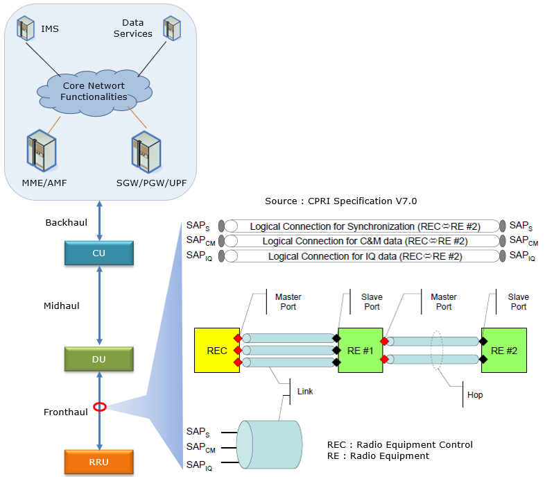
Three horizontal bars run across the top of the right hand picture, and they are worth reading before anything else. They are the three logical connections CPRI carries, and the whole protocol exists to keep all three alive on one fibre.
Term |
Means |
What to know about it |
Radio Equipment Control |
The baseband end. In today's vocabulary this is the BBU, or the DU. |
|
Radio Equipment |
The radio end. The RRU or RRH at the top of the tower. |
|
SAPS |
Synchronisation |
Frequency and frame timing, handed from the REC down to the RE. The radio does not have its own clock in any meaningful sense, it follows this one. |
SAPCM |
Control and Management |
The management channel. Alarms, configuration, software. It comes in a slow flavour and a fast one, both of which appear in the control word section below. |
SAPIQ |
IQ data |
The waveform itself, and essentially all of the bandwidth. Fifteen of every sixteen words on the link belong to this one. |
Two more words from that picture are worth pinning down, because they get used loosely. A
The figure shows RE #1 and RE #2 chained one behind the other, which is why the distinction matters. Radio equipment can be daisy chained, and the second unit is then two hops out. Each unit has a slave port facing the REC and a master port facing further away, and timing always flows from master to slave.
Why CPRI ?
Worth saying first what CPRI is being compared against, because the list below reads oddly otherwise. The alternative was not a slower digital interface. It was a thick coaxial cable running analogue radio frequency up a tower, losing several dB on the way.
CPRI was developed mainly to replace conventional physical media (e.g, Copper cable) and some important motivation for CPRI are as follows :
High Data Rates : CPRI supports very high data rates, up to 25 Gbps, which is much faster than conventional interfaces. This makes it possible to transmit large amounts of data quickly and efficiently.Reduced Latency : CPRI has very low latency, which is the delay between the transmission and reception of data. This is important for real-time applications such as voice and video, where even small delays can affect the quality of the user experience.Improved Flexibility : CPRI allows for more flexible network architectures, as radio equipment can be located farther away from the base station and connected via fiber optic cables. This allows for more efficient use of resources and greater scalability.Cost-Effective : CPRI can reduce the cost of mobile network infrastructure by enabling the use of lower-cost fiber optic cables instead of the more expensive copper cables used in conventional interfaces. Additionally, it can reduce the need for expensive repeaters and amplifiers, as the signal can be transmitted over longer distances without degradation.Interoperability : CPRI is a standardized interface, which means that equipment from different vendors can be easily integrated into the network. This helps to ensure interoperability and reduces the risk of vendor lock-in. ==> Even though CPRI is designed for a standardized interface, there was still room for proprietary implementation, which makes it harder for one CPRI implementation to work with every vendor.
One number in that first bullet is worth tying down. The 25 Gbps figure is CPRI option 10, which is 24,330.24 Mbit/s on the line, and it is the fastest rate the specification defines. The full set of options is in the table further down.
Challenges of CPRI ?
The list below is fair, but none of the five entries is the one that actually killed CPRI for modern radios. That one gets its own section immediately after, because it needs arithmetic rather than adjectives.
One caveat while reading. The interference point applies to the electrical variants, the E.x column in the table below. Optical CPRI runs on fibre and is not troubled by EMI at all, which is a large part of why almost every real deployment is optical.
Even though CPRI has various advantages mentioned above, it has challenges as well. Some of the challenges and disadvantages are listed below.
Complexity : CPRI is a complex technology that requires specialized skills and knowledge to design, implement, and maintain. This can increase the cost of deployment and make it more difficult for smaller operators to adopt.Compatibility: CPRI is not compatible with legacy equipment, which means that operators may need to replace their existing infrastructure in order to adopt the technology. This can be costly and time-consuming.Distance Limitations : While CPRI supports longer distances than conventional interfaces, there are still limitations to the maximum distance that can be covered. This can be a challenge for operators looking to extend their network into remote or rural areas.Interference : CPRI signals can be affected by electromagnetic interference (EMI) from other equipment, which can lead to signal degradation and loss of data. This can be particularly problematic in dense urban environments where there are many sources of EMI.Cost : While CPRI can be cost-effective in the long run, there are initial deployment costs associated with upgrading to the technology. This can be a challenge for operators who are already operating on tight budgets.
How Much Bandwidth Does a Radio Need ?
This is the arithmetic that decides everything, and I would learn it rather than look it up. It is short enough to do in your head.
CPRI carries the sampled waveform, so the rate follows from three numbers and nothing else. How fast the radio samples, how many bits each sample costs, and how many antennas there are.
Take a 20 MHz LTE carrier. It samples at 30.72 Msps, and a common choice is 15 bits for I and 15 for Q, so 30 bits per sample. On two antennas that is 30.72 x 30 x 2, which is 1,843.2 Mbit/s in each direction.
CPRI then adds its own overhead, and it is a fixed fraction rather than a variable one. One word in every sixteen is a control word, so the link has to run 16/15 faster than the IQ rate. That brings 1,843.2 up to 1,966.08 Mbit/s.
Divide by 491.52 and you get exactly 4, which is the multiplier in the options table. So a 20 MHz LTE carrier on two antennas needs option 3, and it fits with nothing to spare.
Doing that for a few configurations makes the problem obvious.
Carrier |
Antennas |
IQ rate |
x 16/15 |
N |
CPRI option |
LTE 20 MHz |
2 |
1,843.2 |
1,966.08 |
4 |
Option 3, 2,457.6 |
LTE 20 MHz |
4 |
3,686.4 |
3,932.16 |
8 |
Option 5, 4,915.2 |
LTE 20 MHz |
8 |
7,372.8 |
7,864.32 |
16 |
Option 7, 9,830.4 |
NR 100 MHz |
2 |
7,372.8 |
7,864.32 |
16 |
Option 7, 9,830.4 |
NR 100 MHz |
117,964.8 |
125,829.12 |
Nothing that exists |
||
NR 100 MHz |
235,929.6 |
251,658.24 |
Nothing that exists |
Every one of those N values comes out as a whole number, which is not luck. With 15 bit IQ the arithmetic collapses to a rule of thumb worth remembering. On a 20 MHz LTE carrier,
The largest option CPRI defines is N of 48. Run that rule backwards and a 100 MHz NR carrier tops out at six antennas on the fastest link the standard has.
Six antenna elements. Not six layers, not six users. A massive MIMO radio has sixty four of them, and often more. That puts the requirement north of 240 Gbit/s on a fibre that can carry 24.
There is no version of CPRI that fixes this, because the problem is the thing being carried. That is what eCPRI exists to change. It moves the split so that what crosses the fronthaul is closer to data and further from waveform, and the rate starts depending on traffic again.
CPRI Options and Bit Rate
Two numbers in the table below do all the work, and neither is explained by the table itself.
491.52 Mbit/s is the rate of one CPRI basic frame per UMTS chip period. A basic frame is 16 words, a word is 8 bits at the lowest option, and the chip period is 1/3.84 MHz. That gives 128 bits every 260.42 ns, which is 491.52 Mbit/s. The whole timebase of CPRI is inherited from UMTS, decades after anyone stopped caring about UMTS.The multiplier in the calculation column is the number of bytes in a word. Option 1 has one byte per word, option 3 has four, option 10 has forty eight. Everything else scales with it.
The last step is line coding, which is pure overhead paid to keep the receiver locked. The 8B/10B scheme costs 25 percent, so the payload rate is multiplied by 10/8. Its replacement, 64B/66B, costs only 3.125 percent and is multiplied by 66/64. That is why the higher options switched to it.
CPRI supports multiple levels of discrete throughput depending on various options that are summarized in the table shown below.
Following table is from the summary of CPRI specification - section 4.2. Physical Layer (Layer 1) Specification
|
Option |
Bit Rate (Mbits/sec) |
Line Coding |
Bit Rate Calculation (Mbits/sec) |
Electrical |
Optical |
|
|
Short Range |
Long Range |
|||||
| Option 1 |
614.4 |
1 x 491.52 x 10/8 |
E.6 |
OS.6 |
OL.6 |
|
| Option 2 |
1,228.8 |
2 x 491.52 x 10/8 |
E.12 |
OS.12 |
OL.12 |
|
| Option 3 |
2,457.6 |
4 x 491.52 x 10/8 |
E.24 |
OS.24 |
OL.24 |
|
| Option 4 |
3,072.0 |
5 x 491.52 x 10/8 |
E.30 |
OS.30 |
OL.30 |
|
| Option 5 |
4,915.2 |
8 x 491.52 x 10/8 |
E.48 |
OS.48 |
OL.48 |
|
| Option 6 |
6,144.0 |
10 x 491.52 x 10/8 |
E.60 |
OS.60 |
OL.60 |
|
| Option 7 |
9,830.4 |
16 x 491.52 x 10/8 |
E.96 |
OS.96 |
OL.96 |
|
| Option 7A |
8,110.08 |
16 x 491.52 x 66/64 |
E.79 |
N/A |
N/A |
|
| Option 8 |
10,137.6 |
20 x 491.52 x 66/64 |
E.99 |
OS.99 |
OL.99 |
|
| Option 9 |
12,165.12 |
24 x 491.52 x 66/64 |
E.119 |
OS.119 |
OL.119 |
|
| Option 10 |
24,330.24 |
48 x 491.52 x 66/64 |
E.238 |
OS.238 |
OL.238 |
|
Frame Structure
Before the hierarchy of containers I would get the timing straight, because CPRI has three nested frame levels and they never change. Not with the bit rate, not with the radio technology.
Level |
Made of |
Duration |
Where the number comes from |
16 words, one of which is the control word |
260.42 ns |
One UMTS chip period, 1/3.84 MHz. Everything on the link is timed off this. |
|
256 basic frames |
66.67 us |
256 x 260.42 ns. Repeats at 15 kHz, which is a number you will recognise from elsewhere. |
|
150 hyperframes |
10 ms |
150 x 66.67 us. This is the one that lines up with the radio frame, and it is counted by the BFN. |
A hyperframe holds 256 basic frames and a 10 ms frame holds 150 hyperframes. Multiply those out and 38,400 basic frames go by every 10 ms. That is 3.84 MHz, which is the UMTS chip rate, and it is the same 3.84 that turns up in the 491.52 Mbit/s figure. CPRI is still keeping time to a technology almost nobody deploys any more.
CPRI frame has multiple levels of hierarchy from the I/Q sample data to hyperframe in the order of
I/Q Samples-->AxC --> AxC Group --> AxC Container --> AxC Container Group --> Basic Frame --> Hyperframe
Basic Frame and Hyper Frame
Four letters index everything in this section and it is easier to read the figures with them in hand.
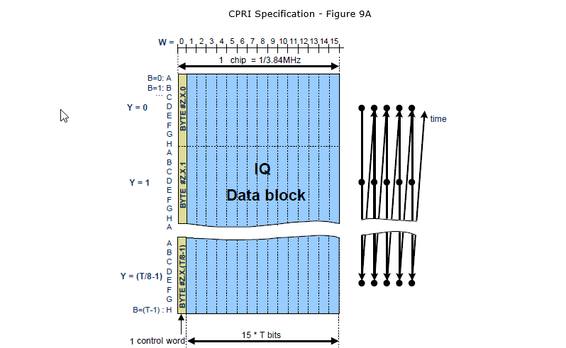
Frame Structure of CPRI is illustrated below. The word number (W) in a basic frame is same but the byte number (Y) is different depending data rate (i.e, CPRI option). The fundamental building block of CPRI frame is called 'basic frame' and 256 basic frames comprises a Hyper frame.
The first figure is one basic frame, drawn as a grid. The narrow yellow column on the left is W of 0, which is the control word, and the blue block is the other fifteen words carrying IQ. Its width spans exactly one chip period, and the label at the bottom, 15 times T bits, is the payload of one basic frame.
So the control overhead of CPRI is not negotiable and not variable. One word in sixteen, which is 6.25 percent, on every link at every speed forever.
The zoomed out part of the figures hows all three levels at once, from the bits of a single word up to the BFN at the bottom. The magnified pair on the left is one word of eight bits next to the IQ block, which is the smallest thing in the picture.
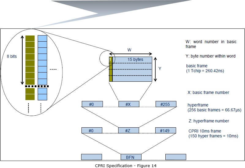
< CPRI specification - Table 6: Value ranges of indices >
The table below is the one that settles what actually changes when you move to a faster option, and the answer is less than you would expect.
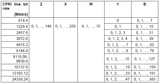
Read down the columns. Z runs 0 to 149 on every row, X runs 0 to 255 on every row, W runs 0 to 15 on every row. Only Y and B move.
In other words the frame structure is the same at 614.4 Mbit/s and at 24 Gbit/s. The words simply get wider. And the widest Y on each row, plus one, is exactly the multiplier from the options table. Option 1 has one byte per word, option 10 has forty eight.
Control Word Frame Structure
One word in every basic frame is control, so a hyperframe carries 256 of them. The clever part is how those 256 are organised, because they are not treated as a stream. I think it is the neatest piece of design in the whole specification.
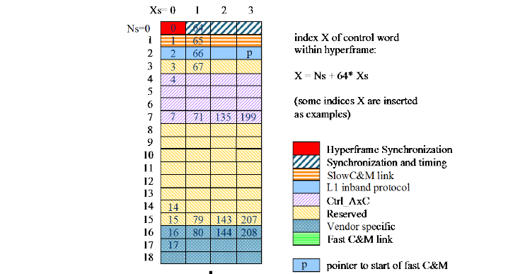
CPRI carries two type of information. One is for data and the other one is for control. Both data and control information is carried together in the basic frame. The position and structure of control information within a basic frame and hyperframe can be illustrated as follows.
They are dealt out into 64 subchannels of four words each, and the figure below is that deal drawn out with the purposes colour coded. The formula in the corner, X equals Ns plus 64 times Xs, is how a subchannel position maps back to a control word index.
Check it against the numbers written in the cells. Subchannel 7 at Xs of 1 is 7 plus 64, which is the 71 printed there. At Xs of 3 it is 7 plus 192, which is the 199. Subchannel 63 holds 63, 127, 191 and 255, the last control word of the hyperframe.
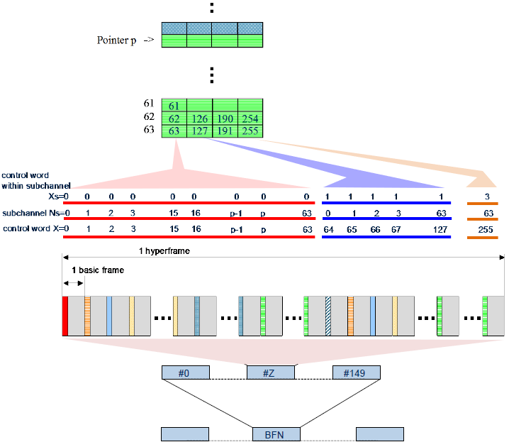
< CPRI specification - Table 7: Implementation of control words within one hyperframe for pointer p > 19 >
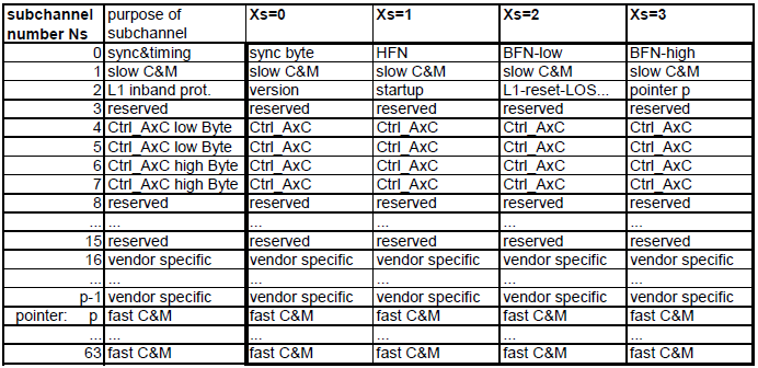
Here is that table read back in plain terms.
Subchannel Ns |
Purpose |
What sits in the four Xs positions |
Sync and timing |
Sync byte, then HFN, then BFN low and BFN high. Four bytes per hyperframe, and the entire timing relationship between REC and RE rests on them. |
|
1 |
Slow C&M |
All four positions. This is the low rate management channel, always present and always in the same place. |
L1 inband protocol |
Version, startup, L1 reset and loss of signal, and then |
|
3 |
Reserved |
Unused. |
4 - 7 |
Ctrl_AxC |
Per antenna-carrier control, split into low byte and high byte pairs. |
8 - 15 |
Reserved |
Unused. |
16 to p-1 |
Vendor specific |
Whatever the equipment maker wants. This is where the interoperability caveat in the Why CPRI section comes home to roost. |
p to 63 |
Fast C&M |
The high rate management channel, typically carrying Ethernet. |
The row worth pausing on is the last pair. Where vendor space ends and fast C&M begins is not fixed by the specification. It is set by pointer p, which arrives in subchannel 2, and the two ends agree on it at startup.
So the management bandwidth of a CPRI link is configurable, and the price of configuring it upward is vendor space. That is also why the pointer p appears as an annotation in both of the figures above rather than as a fixed number.
AxC (Antenna Carrier)
AxC stands for Antenna-Carrier. One antenna-carrier is the amount of digital baseband (IQ) U-plane data necessary for RX and TX of only one carrier at one independent antenna element.
AxC Hierarchy
There are several levels of hierarchy related to AxC that is illustrated in the CPRI specification as shown below.
< CPRI Specification v7.0 - Figure 1A: Illustration of basic definitions >
Time runs left to right in the figure below, and the nesting runs inward. An AxC Group on the far left feeds AxC Containers, and those sit inside an AxC Container Block. The tick marks along the bottom mark off basic frames. Both rows end at the same place, SAPIQ, which is the logical connection from the architecture section at the top of this page.
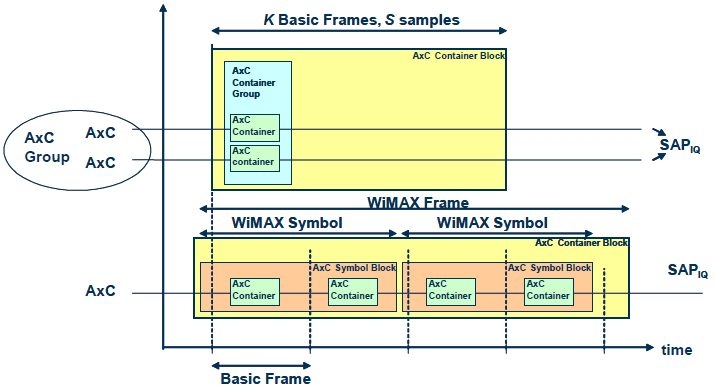
This is description of each components in the hierarchy
-
Antenna-carrier (AxC) : An AxC represents the fundamental unit of digital baseband (IQ) data in a CPRI system, specifically the amount required for either the transmission or reception of a single carrier signal on one independent antenna element. -
AxC Group : An aggregation of multiple AxCs (NA) that share identical attributes, such as sample rate, sample width, destination SAPIQ, and radio frame length. If NA = 1, then the AxC Group is equivalent to a single AxC. -
AxC Container : A discrete segment within the IQ data block of a basic frame. The size is always an even number of bits, and it encapsulates the IQ data of a single AxC for a specific time duration (e.g., one UMTS chip for UTRA-FDD). -
AxC Container Group : This is a collection of NC AxC Containers that hold the IQ samples for a corresponding AxC Group within a single basic frame. The value of NC is determined by parameters such as the number of antennas, carriers, and the specific radio technology being used.
Inter-relation of these components within the hierarchy can be summarized as
-
AxC --> AxC Group --> AxC Container --> AxC Container Group --> Basic Frame --> Hyperframe
Implication of the Hierarchy
High level implication of this hierarchy can be summarized as follows :
-
Data Granularity : The diagram emphasizes the fundamental unit of data transmission, the Antenna-Carrier (AxC). It represents the IQ data for a single antenna carrying a single carrier signal, highlighting the specificity of data streams in modern multi-antenna, multi-carrier systems. -
Hierarchy and Aggregation : The diagram beautifully illustrates the hierarchical aggregation of AxC data into progressively larger structures. AxCs are grouped together based on shared characteristics like sample rate and destination, forming AxC Groups. These groups are then encapsulated into AxC Containers, which are the building blocks of a Basic Frame. -
Frame Structure : The concept of a Basic Frame is pivotal in the diagram. It represents a fixed time duration and acts as a fundamental unit of data transmission in the CPRI link. Multiple AxC Containers can fit within a Basic Frame, and their arrangement is governed by specific rules. -
Flexibility and Vendor Specificity : While the diagram outlines a general framework for CPRI data organization, it also acknowledges the flexibility allowed for vendor-specific implementations. For instance, the content and format of an AxC Container can vary depending on the specific base station architecture and the type of data being transmitted. Modularity : The hierarchical design of CPRI data structures (AxC, AxC Group, Container, etc.) allows for a "building block" approach, where components can be flexibly combined to suit various system configurations and radio technologies.Efficiency : By grouping data into containers and frames, CPRI minimizes the extra information (overhead) needed for transmission, ensuring smooth, timed delivery of information essential for real-time communication.Adaptability : The inclusion of WiMAX-specific elements like AxC Symbol Blocks demonstrates CPRI's ability to adapt to diverse wireless standards, accommodating the unique requirements of each technology.
YouTube
- ORAN (Open Ran) Part-5 : CPRI & eCPRI (Feb 2021)
- Deploying Converged Packet Fronthaul - CPRI Overview | LTE Bandwidth Calculation (May 2021)
- Deploying Converged Packet Fronthaul - CPRI Rate Options Calculation (May 2021)
- Open Fronthaul | Split 7.2x Architecture (Sep 2021)
- CPRI - 10 Things You Need To Know (Oct 2021)
Reference
- Common Public Radio Interface (CPRI); Interface Specification - V7.0
- An Overview of the CPRI Specification and Its Application to C-RAN-Based LTE Scenarios
- CPRI: Common Public Radio Interface
- CPRI structure aware mapper - clarifications
- Low-loss compression of CPRI baseband data
- CPRI Design Example