comm.OFDMDemodulator undoes what the modulator did : it drops the cyclic prefix, transforms back to the frequency domain and discards the guard bands. This page creates the object from the modulator that produced the signal, runs one round trip, and then rebuilds the receive chain by hand.
- Creating OFDM DeModulator
- What do the demodulator properties control ?
- Generating Demodulated OFDM Data with Default Setting
- Generating Demod OFDM Data with Internal Procedure
- Why does the receive chain need an fftshift ?
- What does this example leave out ?
Creating OFDM DeModulator
The listing builds a modulator first, because the demodulator is created from it. Passing hMod to the constructor copies every property the two objects share. The receiver therefore cannot disagree with the transmitter that produced the signal.
hMod = comm.OFDMModulator;
hModInfo = info(hMod);
rng(0);
dataIn = complex(randn(hModInfo.DataInputSize),randn(hModInfo.DataInputSize));
modData = step(hMod,dataIn);
hDeMod = comm.OFDMDemodulator(hMod);
hDeModInfo = info(hDeMod);
|
hDeMod |
|
Properties: FFTLength: 64 NumGuardBandCarriers: [6;5] RemoveDCCarrier: false PilotOutputPort: false CyclicPrefixLength: 16 NumSymbols: 1 NumReceiveAntennas: 1 |
|
hDeModInfo |
|
InputSize: [80 1] DataOutputSize: [53 1] |
FFTLength = NumGuardBandCarriers(1) + DataOutputSize + NumGuardBandCarriers(2) = 6 + 53 + 5 = 64
OutputSize = FFTLength - (NumGuardBandCarriers(1)+NumGuardBandCarriers(2)) = 64 - (6+5) = 53
= InputSize - CyclicPrefixLength - (NumGuardBandCarriers(1)+NumGuardBandCarriers(2))
= 80 - 16 - (6 + 5) = 53
Read the three lines as one argument rather than three facts. The demodulator is handed 80 samples and returns 53, and the two numbers it subtracts are the two things the transmitter added. The cyclic prefix goes first because it is a copy, and the guard bands go next because they were always zero.
The field names on this object read the other way round from the modulator. Here info() reports InputSize and DataOutputSize, because the waveform is now the input and the data is now the result. The first line above uses DataOutputSize for that reason, and the second and third lines are the same calculation reached from the two ends.
Build the demodulator from the modulator : comm.OFDMDemodulator(hMod) copies FFTLength, the guard band sizes and the prefix length in one step. The pair therefore cannot disagree about the symbol they are handling.Both sizes are derived, on this side too : you set FFTLength, the guard bands and the prefix length. The object works out how many samples it expects and how many values it will return.80 in, 53 out, and nothing is lost : 16 of the 27 samples that disappear are copied prefix, and the other 11 carried zero. The payload arrives intact.
What do the demodulator properties control ?
The demodulator lists seven properties where the modulator listed eight, and the missing one is worth noticing before the matching ones. Three more have been renamed to say what they now do, so the two lists look less alike than they are.
Demodulator property |
Default |
Modulator counterpart |
What it does |
FFTLength |
64 |
FFTLength |
The size of the FFT, and therefore how many samples the object takes after the prefix has gone. |
NumGuardBandCarriers |
[6;5] |
NumGuardBandCarriers |
How many positions to discard at the low edge and at the high edge once the transform is done. They were forced to zero at the transmitter, so nothing is lost by dropping them. |
RemoveDCCarrier |
false |
InsertDCNull |
Whether to discard the centre position as well. The transmitter left it carrying data, so the receiver keeps it, and DataOutputSize is 53 rather than 52. |
PilotOutputPort |
false |
PilotInputPort |
Whether pilot values leave through a second output. With false, everything that is not a guard band arrives on the single data output. |
CyclicPrefixLength |
16 |
CyclicPrefixLength |
How many samples to drop from the front of each symbol before transforming. It has to match the transmitter exactly, which is the strongest argument for building this object from that one. |
NumSymbols |
1 |
NumSymbols |
How many OFDM symbols arrive in one step() call. |
NumReceiveAntennas |
1 |
NumTransmitAntennas |
How many input streams the object accepts. |
none |
none |
Windowing |
No receive counterpart exists. Windowing shapes the transition between transmitted symbols to lower the emission outside the band, and a receiver has nothing to undo. |
The three renamed properties all describe the same decision from the other end. InsertDCNull becomes RemoveDCCarrier, PilotInputPort becomes PilotOutputPort, and NumTransmitAntennas becomes NumReceiveAntennas. Nothing about the symbol changes, and only the direction of travel does.
Windowing is the interesting absence. It smooths the joint between one transmitted symbol and the next, which lowers the energy the transmitter radiates outside its channel. That is a courtesy to other users of the spectrum rather than a code applied to the data, so there is nothing for a receiver to reverse. The asymmetry is a useful reminder that a transmit chain and a receive chain are not mirror images of each other throughout.
The matching properties have to match exactly, and that is the reason this page never sets them by hand. Get CyclicPrefixLength wrong by one sample and the receiver transforms a window that straddles two symbols, which destroys every subcarrier at once rather than degrading one. Passing hMod to the constructor removes that whole class of mistake.
Seven properties, not eight : Windowing has no receive counterpart, because it shapes what the transmitter radiates rather than encoding anything the receiver has to decode.Three names change and nothing else does : insert becomes remove, input becomes output, and transmit becomes receive. The underlying decision about the symbol is identical on both sides.A prefix length mismatch is catastrophic rather than gradual : the transform window lands across a symbol boundary, so every subcarrier is wrong at once. That is why the constructor takes the modulator.
Generating Demodulated OFDM Data with Default Setting
This run sends one symbol through the modulator and straight back through the demodulator, with nothing in between. The question it answers is narrow and worth answering anyway : do the 53 values that come out match the 53 that went in ?
hMod = comm.OFDMModulator;
hModInfo = info(hMod);
rng(0);
dataIn = complex(randn(hModInfo.DataInputSize),randn(hModInfo.DataInputSize));
modData = step(hMod,dataIn);
hDeMod = comm.OFDMDemodulator(hMod);
hDeModInfo = info(hDeMod);
deModData = step(hDeMod, modData);
subplot(3,1,1);
stem(abs(dataIn));xlim([1 length(dataIn)]);title('Input Data');
subplot(3,1,2);
stem(abs(modData));xlim([1 length(modData)]); title('Mod Data');
subplot(3,1,3);
stem(abs(deModData));xlim([1 length(deModData)]); title('Demod Data');
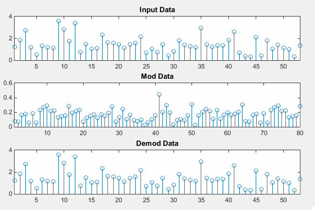
Figure 1. The round trip is exact. The top and bottom panels carry the same 53 magnitudes at the same positions. The 80 sample waveform between them is the only stage at a different vertical scale.
The top and bottom panels are the same picture : 53 values go in and 53 come out, at the same heights and in the same order. Every tall stem appears twice, near index 9, 12 and 35.Only the middle panel has a different scale : Mod Data runs to 0.6 while the other two run to 4. The waveform on the air is roughly eight times smaller than the data at either end of the chain.Nothing sits between the two objects : modData goes straight into step(hDeMod, ...). The exact recovery is arithmetic, and it is not evidence that the chain survives a channel.
The amplitude returns for a reason worth remembering. Matlab puts the 1 over FFTLength factor in ifft and none of it in fft, so the transform pair restores the original scale by itself. The OFDM Modulator page works through the same factor from the transmit end, where it is the reason the middle panel looks flat.
One warning about what Figure 1 proves. It shows that the demodulator inverts the modulator, and it shows nothing at all about receiving a real signal. Nothing stands between the two : no delay, no noise, no frequency offset and no channel. Every part of a receiver that exists to handle those is untested here, and mostly absent.
Generating Demod OFDM Data with Internal Procedure
The second run replaces step() with the three operations it performs, and plots every stage. One line in it does something the transmit side of this example never appeared to do, and the section after this one is about that line.
hMod = comm.OFDMModulator;
hModInfo = info(hMod);
rng(0);
dataIn = complex(randn(hModInfo.DataInputSize),randn(hModInfo.DataInputSize));
modData = step(hMod,dataIn);
modDataNoCP = modData(length(modData)-hMod.FFTLength+1:length(modData));
modDataNoCPfft = fftshift(fft(modDataNoCP));
modDataNoCPfftNpGB = modDataNoCPfft(hMod.NumGuardBandCarriers(1)+1 : ...
length(modDataNoCPfft) - hMod.NumGuardBandCarriers(2));
hDeMod = comm.OFDMDemodulator(hMod);
hDeModInfo = info(hDeMod);
deModData = step(hDeMod, modData);
subplot(6,1,1);
stem(abs(dataIn));xlim([1 length(dataIn)]);
title('Input Data');
set(gca,'xtick',[1 length(dataIn)]);
subplot(6,1,2);
stem(abs(modData));xlim([1 length(modData)]);
title('Mod Data');
set(gca,'xtick',[1 length(modData)]);
subplot(6,1,3);
stem(abs(modDataNoCP));xlim([1 length(modDataNoCP)]);
title('Mod Data - CP Removed');
set(gca,'xtick',[1 length(modDataNoCP)]);
subplot(6,1,4);
stem(abs(modDataNoCPfft));xlim([1 length(modDataNoCPfft)]);
title('ShiftFft(FFT(Mod Data - CP Removed))');
set(gca,'xtick',[1 length(modDataNoCPfft)]);
subplot(6,1,5);
stem(abs(modDataNoCPfftNpGB));xlim([1 length(modDataNoCPfftNpGB)]);
title('ShiftFft(FFT(Mod Data - CP Removed)) - GuardBand Removed');
set(gca,'xtick',[1 length(modDataNoCPfftNpGB)]);
subplot(6,1,6);
stem(abs(deModData));xlim([1 length(deModData)]);
title('Demod Data');
set(gca,'xtick',[1 length(deModData)]);
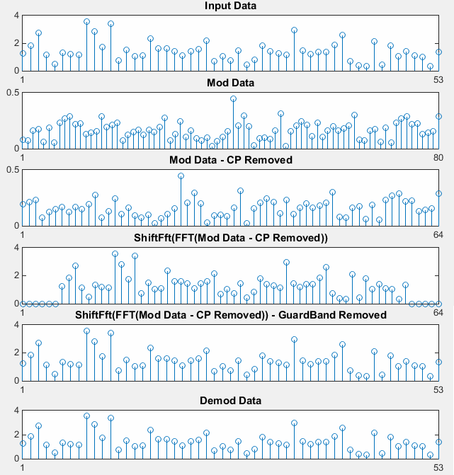
Figure 2. Every stage of the receive chain, with step() repeated at the bottom. The lengths on the x-axes are the argument : 53, 80, 64, 64, 53, 53. The bottom two panels agree, so these three operations are the whole demodulator at these settings.
Each x-axis is labelled only at its two ends : the set(gca,'xtick',...) calls put one tick at 1 and one at the last sample. The length of each stage is therefore what the figure asks you to compare.The scale returns at the transform : panels 2 and 3 run to 0.5, and panels 4, 5 and 6 run to 4. Removing the prefix changes nothing about amplitude, and the FFT restores it in one step.Panel 4 has its zeros at the two ends : the first six and the last five stems sit flat on the axis. That is exactly where the transmitter placed the guard bands, and it is what the next section is about.Panels 5 and 6 agree : slicing the guard bands off panel 4 gives the same 53 values that step() returns. Nothing else is hidden inside the object.
The three lines in the listing map onto panels 3, 4 and 5 in order. The first keeps the last FFTLength samples, which discards the 16 copied prefix samples at the front. The second transforms those 64 samples back to the frequency domain and shifts the result. The third keeps positions 7 through 59, which drops 6 at one end and 5 at the other.
Notice which of those the cyclic prefix gets. It is removed and thrown away, and nothing in this example ever reads it. That is correct, and it is also the whole point of the prefix. A prefix absorbs delay spread before the transform window starts, and with no channel here there is no delay to absorb.
Why does the receive chain need an fftshift ?
One line in the listing above does something the transmit side never appeared to do. The manual receive chain calls fftshift after the fft, while the modulator page rebuilt its transmit chain with a plain ifft and no shift at all. Both descriptions cannot be right.
Panel 4 of Figure 2 settles it, and the detail that settles it is easy to miss. The zeros sit at the two ends of that panel. Work backwards from where they are.
Suppose the modulator had transformed the array exactly as you build it, with the guard bands at positions 1 to 6 and 60 to 64. The fft on the receive side would then return that same array, zeros in the same places. Calling fftshift would move the first 32 entries to the back, which carries those 11 zeros into the middle of the plot. Panel 4 shows them at the ends instead, so the modulator did not work that way.
So comm.OFDMModulator rearranges the array before it transforms it. You supply 64 positions in ascending frequency order, with the guard bands at the two edges. The object maps them to FFT bins, where bin 0 holds DC and the negative frequencies occupy the upper half of the array. Figure 3 draws both orders.
Figure 3. The same 64 positions in the two orders the code moves between. The guard bands sit at the edges in the order you build, and they form one contiguous block in the middle in the order the transform uses. A shift is needed in both directions for that reason.
The zeros at the ends of panel 4 are the evidence : if the object transformed the array as you build it, fftshift would carry those zeros into the middle. They sit at the edges, so the object shifts.You supply ascending frequency, the transform wants bin order : the object converts between the two. That is why the guard bands go at the ends of the array you build rather than around its centre.Shift on both sides or on neither : ifftshift before the ifft and fftshift after the fft belong together. Using one without the other puts every value half a band away from where you put it.
That raises a question about the modulator page, where a plain ifft with no shift appeared to reproduce step() exactly. The appearance came from plotting magnitude. A shift of 32 positions in the frequency domain has one effect in time : every second sample changes sign. Nothing else about the waveform changes. The magnitudes are therefore identical, and two different waveforms give the same stem plot.
The practical warning is worth more than the arithmetic behind it. Build a transmit chain by hand with a plain ifft, plot the magnitude, and everything will look correct. Every data value will be sitting 32 subcarriers away from where you put it. The mistake appears when you demodulate, or when you look at a spectrum, and never before that.
A magnitude plot cannot see this mistake : a shift of half the array in frequency changes the sign of alternate time samples, and abs() hides a change of sign.Check a hand built chain by demodulating it : the round trip in Figure 1 catches subcarrier mapping errors. Inspecting the transmit waveform never reveals them.
What does this example leave out ?
Both examples on this page wire the modulator straight to the demodulator, so the receive chain here does the smallest part of a receiver's job. Everything that makes reception difficult has been removed rather than solved.
There is no channel. Nothing delays the signal, fades it, attenuates it or adds an echo, so the cyclic prefix is discarded without ever having been needed. Its entire purpose is to absorb delay spread before the transform window opens, and that purpose never arises on this page.
There is no noise either. Every recovered value in Figure 1 matches its input to the last digit, which no real receiver ever sees. Add noise and the recovered values scatter around the transmitted ones, and how far they scatter is the number a link budget is really about.
Synchronisation is assumed rather than performed. The code knows the symbol begins at sample 1, and a real receiver has to find that boundary and the carrier frequency for itself. Recall what a one sample error does : the transform window straddles two symbols and every subcarrier is wrong at once.
The last omission is the one that matters most, because it is the reason OFDM is used at all. With a real channel each subcarrier arrives multiplied by a single complex number, so equalization is one division per subcarrier rather than a filter. Estimating those numbers needs known values in the signal, which is what PilotOutputPort would provide and what this example switches off.
The other half of this page is the transmit side. OFDM Modulator builds the signal that arrives here, and OFDM Details goes further into the properties. For the theory behind the transform rather than the toolbox call, OFDM covers the subject on its own.
The prefix is removed without ever having been needed : with no channel there is no delay spread. The prefix costs a fifth of the symbol here and buys nothing.Exact recovery is a property of the arithmetic : it says the demodulator inverts the modulator. It says nothing about how the chain behaves with noise or a channel in the middle.Synchronisation is the hard part and it is missing : finding the symbol boundary and the carrier frequency is most of a real receiver. This example is handed both.One division per subcarrier is the whole reason for OFDM : a flat channel per subcarrier makes equalization trivial. Seeing that needs a channel and pilots, and neither is switched on here.