|
4G/LTE - PHY Channel |
||
|
Resource Allocation and Management Unit
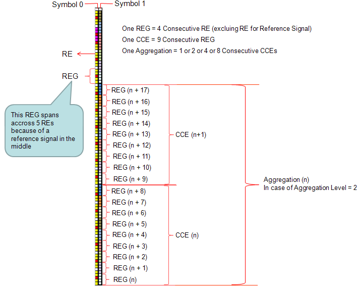
Reading various LTE specification, you will see many terms which seems to be related to resource allocation but looks very confusing. At least you have to clearly understand the following units. Resource Element(RE) : The smallest unit made up of 1 symbol x 1 subcarrier. Resource Element Group (REG) : a group of 4 consecutive resource elements. (resource elements for reference signal is not included in REG) Control Channel Element (CCE) : a group of 9 consective REG Aggregation Level : a group of 'L' CCEs. (L can be 1,2,4,8) RB (Resource Block) : I think everybody would know what this is. This is a unit of 84 resource elements which is 12 subcarrier by 7 symbols (This is with normal Cylic Prefix which is used in most of the LTE deployment. If it is with Extended Cyclic Prefix, the number of symbols within a slot become 6 and the number of resource elements in a single RB become 72). RBG (Resource Block Group) : This is a unit comprised of multiple RBs. How many RBs within one RBG differs depending on the system bandwidth. (Refer to RB Size allocation for each System Bandwidth for the details)
Order of Numbering Units
Following is the overall procedure to number from RE to Aggregation Level.
i) determine the number of OFDM symbols for control region ii) number each REs iii) group REs into REG and number each of the REGs iv) group REGs into CCE and number each of the CCEs v) group CCE according to Aggregation level (let's call this group as a 'CCE Bundle'). vi) Assign one CCE Bundle to one PDCCH
Example
We use these units in hierachical manner depending on whether it is for control channel or data channel.
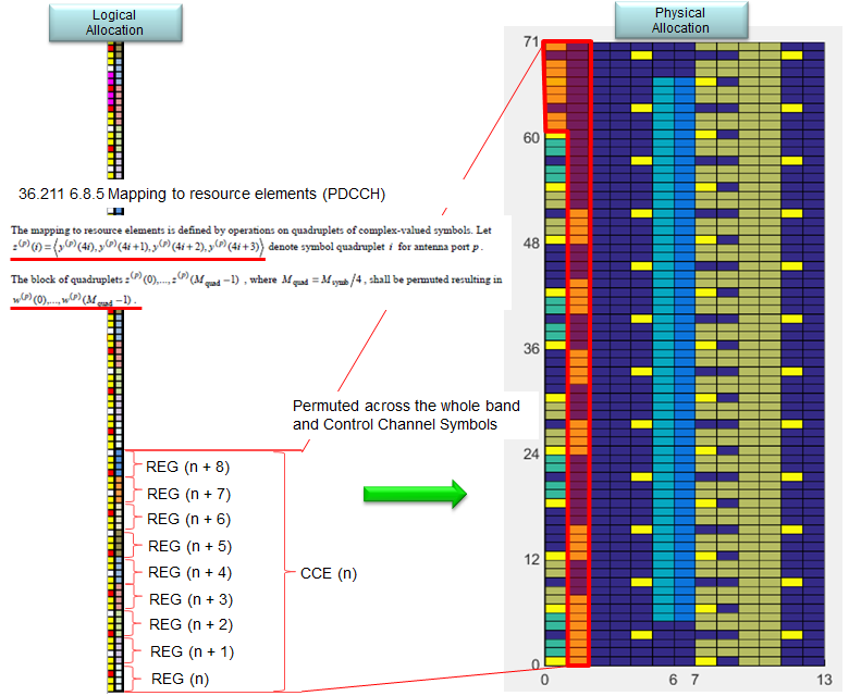
The above illustration would look straightforward but may be a little bit misleading. You may think of the REG arrangement within a CCE is a kind of logical assignment, not physical assignement. The REG arrangement within a CCE is arranged in consecutive manner, but in real (physicall) allocation, the REGs in a CCE get permutated and scattered across the whole bandwidth and control channel symbol as illustrated below.
For further details of physical allocation of REG in control channel, refer to following links.
For PDCCH, the hierachy would be : RE --> REG --> CCE --> Aggregation Level ==> I think a couple of example would give you more practical understanding.
Example 1 > a PDCCH transmission
i) The CCE index for a certain subframe = 4 ii) Aggregation Level is 2 iii) The subframe is sending DCI1 only
Resource Allocation : Network would allocate the DCI 1 spreaded over CCE4, CCE5.
Example 2 > a PDCCH transmission
i) The CCE index for a certain subframe = 4 ii) Aggregation Level is 2 iii) The subframe is sending DCI1, DCI 0
Resource Allocation : Network would allocate the DCI 1 spreaded over CCE4, CCE5 and allocate the DCI 0 spreaded over CCE6, CCE7.
Example 3 > a PDCCH transmission
i) The CCE index for a certain subframe = 4 ii) Aggregation Level is 2 iii) The subframe is sending DCI1, DCI 0 and DCI 3 (power control)
Resource Allocation : Network would allocate the DCI 1 spreaded over CCE4, CCE5 and allocate the DCI 0 spreaded over CCE6, CCE7 and allocate two CCE for DCI 3 but DCI 3 would be allocated to a common search space (not to a user specific search space).
For PDSCH, the heirachy would be RE --> RB --> RBG ==> This is pretty long story. Please refer to Resource Allocation Type
|
||