PBCH is the one channel that coverage enhancement cannot simply configure. Every other channel a BL UE uses is set up by a parameter the UE reads somewhere first. PBCH is where that reading starts, so whatever helps the UE decode it has to be fixed in the specification and known before the UE has decoded anything at all.
Width is not the problem here. PBCH already sits in the middle of the carrier and is only 6 resource blocks wide, whatever the system bandwidth is, so a narrowband receiver reads it without any change. Coverage is the problem. A UE in a basement needs more energy than one 40 ms transmission carries, and legacy PBCH has no repetition to give it.
Release 13 answered that by repeating PBCH inside the radio frame rather than only across frames. This page covers why that was needed, how the repetitions are scheduled, where they land in the resource grid, and what the MIB they carry says to a BL UE.
- Why does PBCH need repetition for a BL UE ?
- MIB Scheduling
- Mapping for PBCH Repetitions
- What the MIB carries for a BL UE
- Reference
Why does PBCH need repetition for a BL UE ?
Every coverage enhancement elsewhere in LTE-M1 is configured. The network sends a repetition count, the UE reads it, and both sides agree. PBCH cannot work that way, because PBCH carries the MIB and the MIB is where the reading starts. So whatever helps a weak UE decode PBCH has to be in the specification, fixed, and applied before the UE knows anything about the cell.
Legacy PBCH gives a normal UE four chances. The payload is coded once and transmitted over four consecutive radio frames, starting in the frame where SFN mod 4 = 0. One subframe #0 carries one of those four. A UE in normal coverage often decodes from one radio frame alone. A UE with a weak enough signal does not decode after the fourth either, and 40 ms have already gone.
Release 13 answers that by adding copies inside the radio frame rather than waiting for the next one. The MIB payload does not change, the coding does not change, and the four-frame schedule does not change. What changes is what sits beside each subframe #0 transmission. Four more copies of the same four symbols now join it, in resource elements a legacy UE does not expect anything in.
Two constraints shape where those copies can go. A legacy UE must not be disturbed, so the repetition can only use resource elements that were already free. 36.211 6.6.4 then declares those elements unavailable for PDSCH and MPDCCH, so nothing else claims them. And a 6 PRB carrier has no spare room at all. That is why 36.211 6.6.4 excludes repetition of the physical broadcast channel when the system bandwidth is 6 resource blocks.
PBCH is the one channel that cannot be configured : it carries the configuration, so its coverage enhancement has to be fixed in the specification rather than signalled.Width was never the difficulty : PBCH is 6 resource blocks wide in the centre of any carrier, so a narrowband receiver reads it unchanged, and only the received energy is short.Repetition adds copies inside the frame, not more frames : the 40 ms schedule and the four-frame transmission are untouched, and the extra copies sit beside the original.A 1.4 MHz cell gets no repetition : 36.211 6.6.4 excludes a 6 resource block system bandwidth, because there are no free resource elements beside PBCH to put the copies in.
MIB Scheduling
The schedule is what decides how many chances a UE gets before it has to give up on the cell. Two numbers matter, and they are easy to confuse. One is how often the contents change, and the other is how often the same contents are sent again. 36.331 states both in one paragraph.
Based on 36.331 5.2.1.2 Scheduling, MIB scheduling is described as below :
The MIB uses a fixed schedule with a periodicity of 40 ms and repetitions made within 40 ms. The first transmission of the MIB is scheduled in subframe #0 of radio frames for which the SFN mod 4 = 0, and repetitions are scheduled in subframe #0 of all other radio frames. For TDD/FDD system with a bandwidth larger than 1.4 MHz that supports BL UEs or UEs in CE, MIB transmission may be repeated in subframe#9 of the previous radio frame for FDD and subframe #5 of the same radio frame for TDD.
This implies that in BL/CE FDD case, a new MIB is transmitted over two subframe (subframe #9 and #0) every 40 ms. But MIB is retransmitted at every subframe where SFN mod 4 is not 0. Therefore, if you see the MIB transmission on spectrum analyzer, you would see the MIB transmission over two subframe at every 10 ms as you see in Example : MIB/SIB1/SIB2 on Spectrum Analyzer
One detail in that schedule is easy to miss, and it explains why the period is 40 ms rather than 10 ms. The MIB carries only the 8 most significant bits of the SFN. 36.211 6.6.1 leaves the 2 least significant bits to be recovered from the position inside the 40 ms PBCH TTI. The first radio frame of the four means 00, the second 01, the third 10 and the last 11. A UE that has combined repetitions therefore learns the full SFN from where in the cycle it decoded, not from a field.
That is also why a repetition is not a retransmission in the HARQ sense. Each of the four radio frames carries a different part of the coded block, so a UE can combine across them. The BL/CE copies inside one frame work the other way round, because each is identical to the transmission it sits beside.
The contents change every 40 ms, the transmission repeats every 10 ms : those are the two numbers the 36.331 paragraph states, and mixing them up makes the spectrum analyzer view look wrong.FDD borrows the subframe before, TDD the subframe after : subframe #9 of the previous radio frame for FDD, subframe #5 of the same radio frame for TDD.The 2 lowest SFN bits are never sent : the UE derives them from which of the four radio frames it decoded, which only works once it knows the 40 ms boundary.A 1.4 MHz cell gets none of this : the 36.331 text conditions the extra repetition on a bandwidth larger than 1.4 MHz, which matches the 36.211 exclusion.
Mapping for PBCH Repetitions
Knowing that PBCH repeats in two subframes still does not say which resource elements the copies use. That question was settled in RAN1 before it reached 36.211, and the contribution below is the one that carried the proposal. Its figure and the table the specification ended up with agree, so the two can be read against each other.
Followings description is from R1-156751. (I don't think I need to put my own comments here since the description in the TDoc is already clear / obvious)
For FDD, in order to optimize coherent combining of repetitions due to the (uncorrected) frequency offset, the subframes with PBCH repetitions are #9 and #0. Figure 1 presents a mapping for PBCH repetitions.
a) 3 symbols per subframe are used for the legacy control region and, after excluding symbols for PSS/SSS, there are a total of 20 symbols for PBCH repetitions (including the legacy one), thereby allowing for an integer number of 5 repetitions (including the legacy one).
b) Symbols labeled ‘1’, ‘2’, ‘3’, and ‘4’ contain respectively the REs for the 1st, 2nd, 3rd, and 4th symbol of the legacy PBCH transmission.
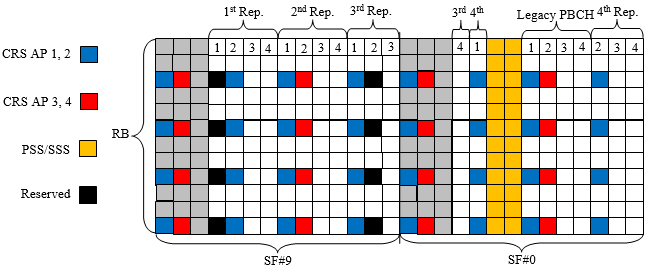
< R1-156751 Figure 1: Mapping for PBCH repetitions in FDD to enable increased SINR for frequency error correction.>
The two braces along the bottom are the subframes : SF#9 on the left and SF#0 on the right, which is the pair the 36.331 paragraph names for FDD.The grey columns at the start of each subframe are the legacy control region : three symbols, which is what item a above removes from the budget before counting repetitions.The yellow block in SF#0 is PSS and SSS : two more symbols out of the budget, which is how 28 symbols in two subframes come down to 20.The numbers are legacy PBCH symbol indices, not repetition indices : a column labelled 3 carries the resource elements of the third symbol of the legacy PBCH, wherever it sits.The third repetition straddles the subframe boundary : its symbols 1, 2 and 3 finish SF#9 and its symbol 4 opens SF#0, which is why the labels 3rd and 4th appear together at the join.The legacy PBCH is the fifth copy, not something apart from them : it sits between the synchronization signals and the tail of the fourth repetition, and a UE combines all five.The black cells marked Reserved carry nothing : they are the CRS positions for antenna ports 2 and 3 in symbols that carry no CRS of their own. Those ports may not exist, so the resource elements are reserved rather than transmitted, and the eNB may use them for PBCH power boosting.
36.211 6.6.4 writes the same mapping as a table, and it is worth putting beside the picture because it is the normative form. Each row is one symbol of the legacy PBCH, and each entry is a place that symbol is repeated. Read a triplet as frame offset, slot number, symbol number, where offset 1 means the previous radio frame and slots 18 and 19 are subframe #9.
Legacy PBCH symbol |
Normal cyclic prefix |
Extended cyclic prefix |
0 | (1,18,3), (1,19,0), (1,19,4), (0,0,4) | (1,18,3), (1,19,0), (1,19,5) |
1 | (1,18,4), (1,19,1), (1,19,5), (0,1,4) | (1,18,4), (1,19,1), (0,0,3) |
2 | (1,18,5), (1,19,2), (1,19,6), (0,1,5) | (1,18,5), (1,19,2), (0,1,4) |
3 | (1,18,6), (1,19,3), (0,0,3), (0,1,6) | (1,19,3), (1,19,4), (0,1,5) |
36.211 Table 6.6.4-1, frame offset, slot and symbol number triplets for repetition of PBCH for frame structure type 1. With normal cyclic prefix each of the four symbols is repeated four times, which gives the 16 repeated symbols that sit beside the 4 legacy ones.
Counting that table against the figure is the quickest way to check either one. Normal cyclic prefix gives four entries per row. Sixteen repeated symbols therefore join the four legacy ones and make twenty, which is the number item a arrives at from the other direction. Extended cyclic prefix gives only three per row, because the shorter slot leaves fewer symbols to spend.
Why subframe #9 and #0, rather than any other pair ? A residual frequency offset makes the received phase turn steadily with time. Two copies far apart in the frame therefore arrive with a large relative phase error, and combining them coherently loses much of what the second copy was worth. Two copies a millisecond apart arrive almost in phase.
Figure 1. The same four copies, placed two ways. Spreading them over the radio frame gives the frequency offset most of 10 ms to turn the phase before the UE combines them. Putting them in adjacent subframes keeps every gap short, which is what the contribution means by optimizing coherent combining.
TDD uses the same idea and a different pair of subframes. 36.331 names subframe #5 of the same radio frame rather than subframe #9 of the previous one, and 36.211 Table 6.6.4-2 gives the slot and symbol pairs. Slots 0 and 1 are subframe #0, and slots 10 and 11 are subframe #5. The entries below are therefore read as slot number and symbol number, with no frame offset.
Legacy PBCH symbol |
Normal cyclic prefix |
Extended cyclic prefix |
0 | (0,3), (1,4), (10,3), (11,0), (11,4) | (0,3), (10,3), (11,0) |
1 | (0,4), (1,5), (10,4), (11,1), (11,5) | (0,4), (10,4), (11,1) |
2 | (0,5), (10,5), (11,2) | (0,5), (10,5), (11,2) |
3 | (0,6), (10,6), (11,3) | (1,4), (11,3), (11,4) |
36.211 Table 6.6.4-2, slot and symbol number pairs for repetition of PBCH for frame structure type 2. The normal cyclic prefix column lists sixteen pairs in total, the same budget FDD gets, although 36.211 drops some of them in one of the two TDD cases.
The figure and the table say the same thing : every column in the picture is one triplet in 36.211 Table 6.6.4-1, so either can be used to check a decoder against the other.Five copies per radio frame, twenty per MIB period : four repetitions plus the legacy transmission, in each of the four radio frames the MIB is sent over.Adjacency is the whole point of #9 and #0 : the pair was chosen so that an uncorrected frequency offset has the least time to turn the phase between copies.Extended cyclic prefix loses one repetition per symbol : three entries per row instead of four, because a shorter slot has fewer symbols to give.TDD keeps the budget and moves the subframes : subframe #0 and subframe #5 of the same radio frame, with the pairs in 36.211 Table 6.6.4-2.
What the MIB carries for a BL UE
All that repetition exists to deliver one small message, and the message is worth reading before leaving PBCH. The MIB is the same information element for every UE, but three of its fields behave differently once the reader is a BL UE. One of them decides whether the UE may use the cell at all.
Following is based on
MasterInformationBlock ::=     SEQUENCE {
    dl-Bandwidth                   ENUMERATED {
                                        n6, n15, n25, n50, n75, n100},
    phich-Config                   PHICH-Config,
    systemFrameNumber              BIT STRING (SIZE (8)),
    schedulingInfoSIB1-BR-r13      INTEGER (0..31),
    systemInfoUnchanged-BR-r15     BOOLEAN,
    partEARFCN-r17                 CHOICE {
        spare                          BIT STRING (SIZE (2)),
        earfcn-LSB                     BIT STRING (SIZE (2))
    },
    spare                          BIT STRING (SIZE (1))
}
schedulingInfoSIB1-BR-r13 is the field that makes the cell usable. It is an index into the tables in 36.213 Table 7.1.6-1 and Table 7.1.7.2.7-1, and those tables give the subframe, the transport block size and the narrowband for SystemInformationBlockType1-BR. The value 0 means SystemInformationBlockType1-BR is not scheduled, and a BL UE that reads 0 treats the cell as barred and looks elsewhere.
That is the whole mechanism behind a rule the BL/CE page states plainly. A BL UE may access a cell only if the MIB says SIB1 for BL UEs is scheduled. There is no separate barring flag, and no control channel to ask. Five bits in the MIB either point at a schedule or they do not.
phich-Config is the opposite case. It stays in the MIB for every UE, and 36.331 says a BL UE or a UE in CE shall ignore it. LTE-M1 has no PHICH to configure, as the BL/CE page sets out, so those three bits carry nothing a BL UE can use.
systemFrameNumber is the field the scheduling section already touched. Only the 8 most significant bits travel in the MIB, and 36.211 6.6.1 leaves the remaining 2 to be read off the position inside the 40 ms PBCH TTI.
Two later fields close the listing. The Release 15 addition, systemInfoUnchanged-BR-r15, is a single bit. It says nothing in SIB1-BR or the SI messages has changed over the SI validity time, so a UE can skip re-reading system information it already holds. The Release 17 addition, partEARFCN-r17, carries the 2 least significant bits of the EARFCN for the non-terrestrial bands that use a 100 kHz raster. After those, one spare bit is left.
schedulingInfoSIB1-BR-r13 is the access gate : a value of 0 means SIB1-BR is not scheduled, and the BL UE treats the cell as barred without any other signal.A BL UE ignores phich-Config : 36.331 says so outright, because LTE-M1 has no PHICH to configure.The MIB never sends the full SFN : 8 bits travel, and the last 2 come from which radio frame of the 40 ms period the UE decoded.The spare room is nearly gone : Release 13, Release 15 and Release 17 each took bits out of what used to be spare, and the listing now ends with a single spare bit.
Reference
The contribution the mapping came from, and the clauses it was written into.
[1] 3GPP R1-156751 3GPP TSG RAN WG1 #83 - Mapping for PBCH Repetitions
[2] 3GPP TS 36.211 v19.3.0 - clause 6.6 Physical broadcast channel, with Table 6.6.4-1 and Table 6.6.4-2
[3] 3GPP TS 36.331 v19.3.0 - clause 5.2.1.2 Scheduling, and the MasterInformationBlock information element
[4] 3GPP TS 36.213 v19.4.0 - Table 7.1.6-1 and Table 7.1.7.2.7-1, the SystemInformationBlockType1-BR schedules