|
Satellite-Mobile Communication
Imagine talking to someone far away like in deep forest or in the middle of ocean or even in another country, using your mobile phone. Have you ever wondered how your voice or message travels such long distances? A big part of the answer lies up in the sky with satellites (assuming that there is no roaming service).
Satellites are like big mirrors in space that bounce signals from one point on Earth to another, including the signal from your mobile phone. This is how we can send messages, make calls, and use the internet on our phones, even when we're in places where there are no phone towers nearby.
In this note, we're going to talk about how satellites and mobile phones talk to each other. It's a bit like playing catch with a ball, but instead of throwing a ball back and forth, we're sending invisible signals up to the sky and back down to Earth. This technology has made it possible for us to stay connected with people no matter where they are, even in the middle of the ocean or on top of a mountain.
We'll also look at what makes this communication challenging, how smart people are working to make it better, and what exciting things we can expect in the future. So, join us as we explore this amazing technology that keeps us connected to the world.
Communicating between satellites and mobile phones, despite its widespread use and critical importance, faces several challenges. These challenges can affect how well and how reliably we can communicate, especially in remote areas or during critical situations.
- Latency Issues: Latency is the delay before a transfer of data begins following an instruction for its transfer. In satellite communication, signals have to travel thousands of kilometers to space and back, which can cause a noticeable delay. This is particularly problematic for real-time applications like video calls or online gaming.
- Implication on Implementation: The inherent delay in satellite communication due to the long distance signals must travel presents a challenge to meeting these latency requirements. To align with 3GPP standards, satellite communication systems need to implement techniques like onboard processing and optimized routing to reduce latency, ensuring
compatibility
with applications demanding low delay, such as VoLTE (Voice over LTE) and real-time gaming. ==> We may try hard to reduce the latency by data/signal processing on UE and Satellite side, but there wouldn't be much thing to do with the delay caused by propogation delay between UE and Satellite.
- Doppler Shift : One of the significant challenges is the Doppler shift. This phenomenon occurs because the satellite and the mobile phone are moving relative to each other. As the satellite orbits Earth, its speed causes the frequency of the signals it sends and receives to change slightly. This effect can make it difficult for the mobile phone to accurately pick up the signal, as the frequency might shift out of the phone's expected range. Overcoming the Doppler shift requires
sophisticated
technology in both satellites and mobile phones to adjust the frequencies of the signals they send and receive.
- Implication on Implementation: :The 3GPP standards include specific provisions for compensating frequency variations, including those caused by the Doppler effect, especially in high-speed scenarios like high-speed trains. For satellite communications, adapting these standards means developing more sophisticated Doppler shift compensation algorithms that can handle the relative movement between satellites and mobile phones. This ensures consistent signal quality and reliability
across
all mobile
networks, including those extended through satellite links.
- Delay Spread : Another challenge is delay spread, which refers to variations in signal travel times due to different paths the signal might take. In satellite communication, while the open space minimizes obstacles, the immense distances the signal travels can cause parts of it to arrive at slightly different times. This variation can distort the received signal, affecting the quality and clarity of the communication.
- Implication on Implementation: : Delay spread, with its potential to distort signals, directly impacts the Orthogonal Frequency-Division Multiplexing (OFDM) technology used in LTE and 5G networks, as defined by 3GPP. OFDM is sensitive to timing discrepancies, which can cause inter-symbol interference. Addressing delay spread in satellite communications involves incorporating advanced equalization and timing correction techniques that are robust enough to handle the variations,
thereby
aligning with
3GPP standards that aim for high-quality, clear communication.
- Transmission Power : The vast distance between satellites and mobile phones also poses a challenge for transmission power. Transmitting a signal across thousands of miles requires significant power, but satellites are limited by their size, weight, and the solar energy they can collect. Balancing the need for a strong, clear signal with these power constraints requires careful engineering and power management.
- Implication on Implementation: : The 3GPP specifications detail power control mechanisms to optimize signal strength and quality while minimizing interference and power consumption. In the context of satellite communications, adhering to these specifications means developing satellite payloads and mobile devices that can operate effectively within the power constraints set by 3GPP. This involves leveraging highly efficient power amplifiers, smart power management systems,
and adaptive
transmission
techniques to ensure that both uplink and downlink communications meet the power requirements and constraints defined by 3GPP.
- Receiver Sensitivity : On the receiving end, mobile phones and satellite must have the sensitivity to detect the satellite's signal, which can be weak and prone to interference. Improving a mobile phone's receiver sensitivity without significantly increasing its power consumption or cost is an ongoing challenge in the field.
- Implication on Implementation: : Receiver sensitivity is crucial for achieving the high-performance levels specified by 3GPP, particularly in challenging signal conditions. For satellite communications, enhancing receiver sensitivity to meet 3GPP standards involves deploying advanced noise reduction and signal processing technologies. This ensures that mobile phones and satellite receivers can detect and decode signals effectively, even at the low signal-to-noise ratios
common in satellite
links,
thereby supporting the reliable, high-quality service expected from 3GPP-compliant networks.
Addressing the challenges of satellite communication involves innovative workarounds and technologies, particularly when considering the integration of satellite systems with conventional User Equipment (UE) and Non-Terrestrial Network (NTN) capable UE, as defined by 3GPP standards.
NOTE : I guess most of the demo(pre-deployment ?) shown in 2020 or earlier is based on the satellite and non NTN UE (regular mobile phone without supporting NTN) because it is before the finalization of 3GPP NTN specification or UE modem chipset availability and they claim that the communication is possible with existing mobile phone without any modification. But almost no technical details in terms of protocol issues. So my comments on non-NTN devices are from my speculation.
- Latency Issues
- Satellite: I can think of a few options.
- Choice of orbit (LEO or GEO). This would be the biggest factor.
- Choice of eNB/gNB configuration : RACH Preamble type, RAR window size, Contention Resolution Window, HARQ related parameters etc.
- Employing the advanced DSP to reduce the internal delay may do some help but not as much of orbit choice.
- Conventional UE: According to the claims from various satellite solution provider, there wouldn't be any special tricks required.
- NTN Capable UE: Compliance to NTN specification (e.g, handling large TA(Timing Advance), HARQ requirement)
- Doppler Shift
- Satellite: Design satellites and their payloads with advanced frequency compensation technologies that automatically adjust for Doppler shifts caused by their movement relative to the Earth. Doppler shift can be compensated both by Satellite and UE, but I think the compensation by Satellite would be the major factor.
- Conventional UE: According to the claims from various satellite solution provider, there wouldn't be any special tricks required.
- NTN Capable UE: How to handle Doppler shift is not directly specified by 3GPP, but advanced DSP(e.g CFO (Channel Frequency Offset) compensator, Advanced Channel Estimator / Equalizer) would be a great help.
- Delay Spread
- Satellite: Employ advanced modulation and coding schemes that are more resilient to the effects of delay spread, as well as smart beamforming technologies that can focus signals more directly to the intended receiver, reducing multipath interference.
- Conventional UE: According to the claims from various satellite solution provider, there wouldn't be any special tricks required.
- NTN Capable UE: NTN-capable UEs can use more advanced equalization and error correction protocols that are optimized for the unique challenges of satellite communication, including delay spread.
- Transmission Power
- Satellite: I think this should be handled mostly by Satellite using special techniques as below
- High Power / High Gain Antenna. Due to this, the satellites for cellular communication has antenna with huge size
- Advanced Beam Forming
- Conventional UE: There wouldn't be any breakthrough on UE side because the max power from UE is strictly limited by 3GPP.
- NTN Capable UE: There wouldn't be any breakthrough on UE side because the max power from UE is strictly limited by 3GPP
- Receiver Sensitivity
- Satellite: Like TX power, I think this should be handled mostly by Satellite using special techniques as below
- High Power / High Gain Antenna. Due to this, the satellites for cellular communication has antenna with huge size
- Advanced LNA.
- The environment around satellite (very low temperature comparing to terrestrial environment) can be a strong positive factor (i.e, very low thermal noise)
- Conventional UE: According to the claims from various satellite solution provider, there wouldn't be any special tricks required.
- NTN Capable UE: Application of high quality LNA, advanced Equalizer etc can help.
The idea of universal access provided by the communication between satellite and mobile phone would sound fancy. Imagine a world where your smartphone connects seamlessly to the internet, no matter where you stand—deep in a forest, adrift at sea, or atop a remote mountain. This is the tantalizing dream of universal access, fueled by satellite technology like Direct-to-Cell or NTN. However, making this happen isn’t easy. Companies face big challenges: huge antennas that make satellites
expensive, lots of satellites that cost a fortune, and a tough choice between low orbits for fast signals or high orbits to cover more places. The dream of connecting everyone is amazing, but the real-world problems of cost and technology are just as huge.
In this section, I want to talk about a couple of critical trade-off (dilemmas) we need to overcome. I don't have any clear answer to this dilemmas but I wanted to clarify on what we should overcome (i.e, clear definition of problem itself).
Antenna Size and Satellite Design
To enable direct communication with standard user equipment (UE) like mobile phones—without requiring specialized hardware—the satellite needs a large antenna (e.g., AST SpaceMobile’s 64 m² or Starlink’s 25 m²). This increases the satellite's size, complexity, and cost.
Larger antennas are necessary to focus radio signals into a sufficiently strong beam to reach small, low-power devices like smartphones. This is because standard phones have limited transmission power and small antennas compared to dedicated satellite receivers. However, scaling up the antenna size poses challenges:
- Launch Constraints: Larger satellites require more powerful (and expensive) launch vehicles, and there are physical limits to how big a satellite can be while still fitting into a rocket fairing. Techniques like deployable antennas (e.g., phased arrays that unfold in space) help, but they add engineering complexity and risk of failure.
- Power Requirements: Bigger antennas and the associated electronics demand more power, necessitating larger solar panels and batteries, further driving up size, weight, and cost.
- Cost Implications: The manufacturing, testing, and deployment of such satellites become significantly more expensive, making it a high-stakes investment for companies aiming to scale this technology.
Orbit Altitude and Propagation Delay vs. Coverage
Lower orbits (e.g., Low Earth Orbit, LEO, at 300-2000 km) reduce propagation delay, which is critical for real-time applications like voice calls or gaming. However, LEO satellites have a smaller coverage footprint, requiring a large constellation for continuous service, which increases costs. Conversely, higher orbits (e.g., Geostationary Orbit, GEO, at ~36,000 km) allow fewer satellites to cover vast areas but introduce significant delays (~250-300 ms one-way), degrading performance.
- LEO Challenges: In LEO, satellites move rapidly relative to the Earth (e.g., orbiting every 90-120 minutes), so a single satellite can only serve a given area for a few minutes before handing off to another. This necessitates a dense constellation—hundreds or thousands of satellites (e.g., Starlink’s planned 42,000)—to ensure no coverage gaps. The sheer scale drives up costs for manufacturing, launch, and orbital management (e.g., collision avoidance, deorbiting).
- GEO Trade-offs: GEO satellites remain fixed over one spot, providing continuous coverage with just a few satellites (e.g., 3 GEO satellites can cover most of the planet). However, the long distance introduces latency that’s unacceptable for latency-sensitive applications. Additionally, the signal strength weakens over such distances, requiring either more powerful satellite transmitters or slight UE hardware modifications—contradicting the "no special hardware" goal.
- Middle Ground (MEO): Medium Earth Orbit (MEO, 2,000-20,000 km) offers a compromise, with moderate latency (~50-150 ms) and fewer satellites than LEO (e.g., O3b’s constellation uses ~20 satellites). However, MEO still requires more satellites than GEO and doesn’t fully solve the latency or coverage density issues.
Number of Satellites and Investment Scale
A LEO constellation requires a massive number of satellites for continuous coverage, demanding enormous upfront investment. Higher orbits reduce the satellite count but compromise performance due to delay.
- LEO Economics: Building, launching, and maintaining thousands of satellites (e.g., Starlink’s $10+ billion investment) is a capital-intensive endeavor. Companies must also account for satellite lifespan (5-7 years in LEO due to atmospheric drag) and replacement costs. However, LEO’s lower latency and higher throughput potential (e.g., 20-150 Mbps for Starlink) make it attractive for consumer markets if costs can be amortized over millions of users.
- GEO Economics: GEO satellites are expensive individually (hundreds of millions each), but fewer are needed, reducing total constellation costs. However, their high latency limits them to applications like broadcasting or low-bandwidth IoT, not broadband or real-time mobile services.
- Spectrum and Interference: Both approaches require access to radio spectrum, which is a finite and regulated resource. LEO constellations may face interference challenges due to their density, while GEO satellites must compete with existing users in higher bands.
Delivering LTE and 5G services directly from low‑Earth‑orbit satellites forces protocols built for terrestrial cell sites to cope with a propagation delay an order of magnitude larger than they were originally designed for. Random‑access handshakes, HARQ acknowledgements, timing‑advance corrections, and other millisecond‑level control loops must still complete on time even though each signal now travels hundreds of kilometres into space and back. This section maps these tight air‑interface
budgets against the true radio round‑trip of a LEO link, then shows how careful orbit geometry, on‑board base‑station processing, existing flexibility in LTE‑TDD and NR timing tables, and—when necessary—upper‑layer retransmission techniques keep every critical timer inside spec without modifying today’s handsets
NOTE : Most of the mitigation techniques mentioned here is not specified in 3GPP and mostly proprietary which are not explicitely open to public. Each of the satellite service provider would use different cocktails of the tricks and some of them would use other tricks which is not mentioned here. So take these tricks in this secion as a kind of potential/feasible tricks for brain storming.
Cellular Timing Budgets vs. LEO Satellite Round‑Trip Delay
Conventional cellular protocols have always relied on sub‑millisecond reflexes between a handset and a tower a few kilometres away, yet a low‑Earth‑orbit link stretches that path to hundreds of kilometres without breaking the rhythm—if every micro‑process in the stack is re‑examined. The table below isolates each timing‑critical loop in LTE and NR, lays its terrestrial budget beside the raw round‑trip that space imposes, then reveals whether the margin survives untouched or must be rescued
by clever engineering
|
Loop / timer (spec default)
|
Terrestrial budget
|
Worst‑case LEO radio RTT
(≈ 550 km @ 30 ° elev.)
|
Why it can fail
|
Mitigation knobs already inside vanilla LTE / NR
|
|
PRACH → RAR
ra‑ResponseWindowSize = 0–10 SF (2–10 ms)
|
2–10 ms
|
5–7 ms
|
Works only if RAR built instantly on board
|
Satellite MAC sends Msg 2 in next DL SF
Schedule RA bursts when elev ≥ 45 ° (RTT ≈ 4 ms)
|
|
Contention‑Resolution
|
24–64 ms
|
5–7 ms
|
Ample margin
|
No change required
|
|
Timing‑Advance
max ≈ 667 µs (~ 100 km)
|
0–667 µs
|
1.7–3.7 ms
|
UE cannot request such large TA
|
Satellite pre‑shifts DL frame start so residual TA < 667 µs
Grant‑free UL for SMS
|
|
HARQ ACK/NACK
LTE‑FDD fixed n + 4 = 4 ms
|
4 ms
|
5–7 ms
|
ACK misses window
|
Use LTE‑TDD offset 7–11 ms
NR flexible k1 0‑15 (≤ 16 ms)
Disable L1 HARQ for SMS/alerts
|
|
CSI / CQI feedback
|
4–8 ms
|
5–7 ms
|
Same risk as HARQ
|
Same tools: TDD timing, NR k1, or feedback‑off mode + repetition
|
|
Scheduling Request (SR)
|
≥ 8 ms period
|
5–7 ms
|
Usually fits
|
Schedule SR only at high elevation if margin tight
|
|
Paging cycle
|
≥ 160 ms
|
—
|
Always fits
|
Satellite repeats paging bursts for diversity
|
Generic mitigation toolbox
The tricks listed in this section is an extension to the list in previous section. The table below lists a set of practical tricks that let a normal LTE or 5G phone work even when its “cell tower” is a fast‑moving satellite in low orbit. Each trick tackles one of the big space problems—extra delay, fast Doppler shifts, or gaps in coverage—while leaving the phone itself unchanged. Some ideas use room that already exists in the standards, like a longer ACK time in LTE‑TDD. Others add a small,
fixed delay on purpose so the up‑link and down‑link keep the same rhythm. When tight timing still cannot be met, the network simply repeats messages or lets a higher layer retry. Finally, operators turn on only the easiest services first, such as text messages and alerts, and wait until more satellites are in the sky before enabling voice and full data. Together, these methods hide the extra space delay and make the satellite cell feel almost the same as an ordinary ground cell to the user.
|
Tactic
|
Core idea
|
|
Geometry gating
|
Serve traffic only when satellite elevation ≥ 45 °, keeping two‑way propagation ≤ 4 ms so even the tightest HARQ/FDD timers are met.
|
|
Integer‑slot delay padding (kmac)
|
Compute the worst‑case RTT, round it to an integer number of slots, then add artificial DL delay so “actual RTT + padding = kmac”. From the UE’s view the cell looks time‑stationary and all UL/DL timing stays deterministic.
|
|
LTE‑TDD / NR flexible ACK offsets
|
Exploit built‑in 7‑– 11 ms ACK gaps in LTE‑TDD or NR k1 = 0‑15 (≤ 16 ms) instead of the fixed 4 ms LTE‑FDD window.
|
|
Layer‑1 HARQ disable + repetition
|
Turn off HARQ feedback for SMS, cell‑broadcast and low‑rate voice; rely on heavy DL repetition and RLC/NAS retransmission for reliability.
|
|
PRACH window juggling
|
Constrain PRACH period/config so the UE always re‑uses the same preamble; ignore that second preamble and instead send the RAR for the first PRACH inside the second RAR window. The UE receives a timely RAR and proceeds as if the first attempt succeeded.
|
|
Rel‑17 HARQ‑RTT timers (future‑proof)
|
Use HARQ‑RTT‑TimerDL/UL‑NTN so the gNB advertises “terrestrial value + measured RTT”, allowing legacy HARQ logic to work at any distance.
|
|
Large code blocks / long TTIs
|
Invoke 2‑, 4‑, 8 ‑ms TTIs in LTE‑M or NR RedCap so ACK/NACK naturally arrives after the longer transmission interval, absorbing the space delay.
|
|
On‑orbit gNB/eNB processing
|
Terminate all fast loops (PRACH, TA, HARQ, SR) inside the satellite; only user payload tunnels back to ground, so back‑haul latency is irrelevant to air‑interface timing.
|
|
Frame‑start pre‑compensation
|
Transmit DL frames slightly early so the UE receives them “on time”; residual TA request remains within the 0‑– 667 µs spec limit.
|
|
Phased service rollout
|
Begin with store‑and‑forward SMS and broadcast alerts (most tolerant), add voice once timing tricks are proven, then enable packet data as constellation density grows.
|
NOTE: On‑orbit processing, geometry‑aware scheduling, existing LTE‑TDD / NR k1 flexibility, the option to drop L1 HARQ, and longer TTIs let a LEO satellite satisfy every critical timing window—even without any handset NTN extensions. 3GPP Rel‑17 merely formalises what these work‑arounds already achieve.
When a satellite rushes overhead at nearly 8 km /s, every
radio signal between the phone and its “space cell” slides tens of
kilohertz up or down in frequency, and that shift is changing
hundreds of hertz every second. This section will describe on how this fast, large Doppler shift collides with the
frequency‑error limits that LTE and 5 G were written for, and then
list the common engineering tricks that can mitigate those problems.
NOTE : Most of the mitigation techniques mentioned here is not specified in 3GPP and mostly proprietary which are not explicitely open to public. Each of the satellite service provider would use different cocktails of the tricks and some of them would use other tricks which is not mentioned here. So take these tricks in this secion as a kind of potential/feasible tricks for brain storming.
Cellular Doppler Budgets vs. LEO Satellite Doppler
A signal sent from a phone to a low‑Earth‑orbit satellite is hit by a Doppler shift that can move its frequency tens of kilohertz and change thousands of hertz every second, far more than a ground network ever sees. The table compares those fast, large shifts with the much smaller frequency‑error limits built into LTE and 5G procedures such as cell search, sub‑carrier alignment, and PRACH timing. It then shows the standard tricks engineers rely on to keep each procedure inside its original
tolerance. Together these measures let an ordinary handset lock onto and stay connected to a cell that is racing across the sky.
|
Loop / check‑point
|
Spec tolerance
|
LEO worst‑case Doppler
(7.5 km /s, f ≈ 0.7–2 GHz)
|
Why it can fail
|
Fixes inside plain LTE / NR
|
|
PSS / SSB detection
(initial cell search)
|
±20 ppm CFO window (≈ ±14 kHz @ 700 MHz,
±38 kHz @ 1.9 GHz)
|
17 – 50 kHz static + large rate of change
|
Doppler can sit outside the search grid
|
Satellite sends DL pre‑rotated; phone widens search grid in firmware or scans coarse steps.
|
|
OFDM subcarrier orthogonality
|
Residual CFO (10 % of 15 kHz SCS)
|
Up to 50 kHz if un‑corrected
|
I/Q leakage, inter‑carrier interference
|
Fine CFO tracker per OFDM symbol; larger SCS (30/60 kHz in NR) lowers % error.
|
|
Uplink frequency error seen by gNB
|
UE spec: ±0.1 ppm
(±70 Hz @ 700 MHz)
|
17 – 50 kHz added Doppler
|
Satellite cannot decode UL unless error removed
|
On‑board derotation using predicted Doppler; per‑sub‑frame CFO estimate and cancel.
|
|
Doppler rate of change
|
High‑speed train profile: < 950 Hz/s
|
≈ 5 – 8 kHz/s @ 2 GHz
|
Tracking loops lose lock
|
Update CFO every OFDM symbol; use pilot‑aided phase tracking.
|
|
PRACH preamble timing
|
Cyclic prefix = 316 µs
(Format 0/A3)
|
Doppler‑induced timing drift 5 µs over 10 ms
|
Preamble may slip outside CP
|
High‑rate TA update in satellite receiver; choose PRACH formats with longer CP when possible.
|
Generic mitigation toolbox — Doppler shift
The list below gathers the practical fixes engineers apply so the handset never notices that its serving tower is racing through space. Some solutions are simple—wait until the satellite is high overhead or shift the satellite’s carrier by the expected amount—while others work in the background, such as tiny frequency tweaks every OFDM symbol or extra‑wide sub‑carrier spacing. A few tactics give the phone more room to find the signal, repeating the sync blocks or asking the handset to scan a wider band. Together these measures chase the Doppler error down to a level that fits inside the normal LTE and 5 G limits, allowing everyday devices to connect as if the cell were standing still.
|
Tactic
|
Core idea
|
|
Geometry gating
|
Only talk when the satellite is high in the sky; Doppler is then smaller and changes more slowly.
|
|
Down‑link pre‑compensation
|
Satellite transmitter shifts its own carrier by the expected Doppler so the phone hears the correct frequency.
|
|
Uplink derotation
|
The satellite receiver mixes (rotates) the received signal by the opposite Doppler, cancelling the error before demodulation.
|
|
Fine CFO tracker per OFDM symbol
|
Use pilot tones in each symbol to measure and remove the small remaining error that changes symbol‑to‑symbol.
|
|
Use wider sub‑carrier spacing
|
Moving from 15 kHz (legacy LTE) to 30 / 60 kHz (NR) makes the same Doppler a smaller fraction of the tone spacing.
|
|
Enlarge cell‑search window
|
Let the phone scan a bigger frequency range during PSS/SSB search, or guide it with an assistance message.
|
|
Frequent TA / CFO updates
|
The satellite gNB sends timing‑advance and frequency‑correction commands every few milliseconds to keep the phone aligned.
|
|
SSB / PSS repetition and boosting
|
Transmit multiple, stronger sync blocks so at least one lands inside the phone’s extended search grid despite Doppler.
|
|
Higher‑layer retries for PRACH
|
If a PRACH misses due to extreme Doppler, the phone re‑sends; eNB answers on the second window, which still looks “on time” to the UE.
|
|
Rel‑17 & beyond (future‑proof)
|
Although not required, the new NTN options formalise larger frequency errors and faster tracking so future devices handle Doppler natively.
|
Satellite to cellular communication is not a wish-to-have technology any more. There are several solutions that are already deployed (or at least demonstrated / proved working). Followings are a list of these solution :
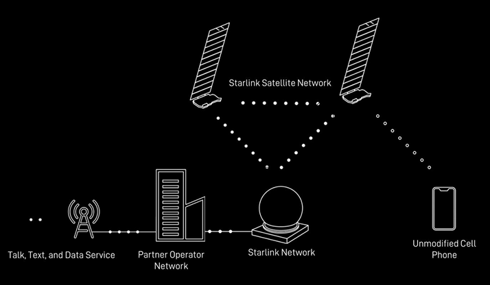
Source : SPACEX SENDS FIRST TEXT MESSAGES VIA ITS NEWLY LAUNCHED DIRECT TO CELL SATELLITES
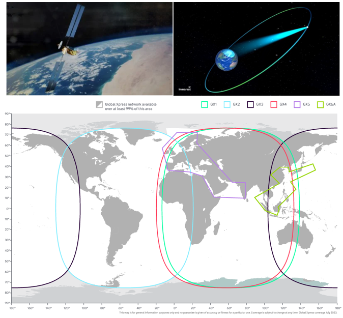
Source : Satellites - inmarsat
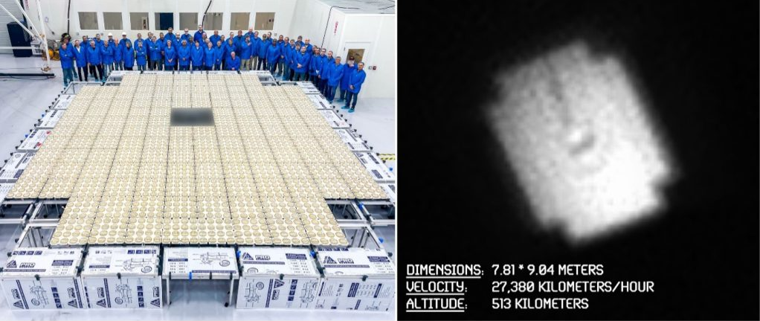
Source : AST/SpaceMobile
YouTube
Reference
|
|