Project Kuiper is Amazon's satellite broadband initiative, renamed Amazon Leo on 13 November 2025. Its original 2019 application described a 3,236-satellite Ka-band system with dedicated customer terminals and gateways. The supplied 2026 document describes a separate Direct-to-Device constellation using lower-frequency mobile service links. These systems serve different terminal types and should not be treated as interchangeable generations of one radio link. [A]
This note compares the supplied FCC application attachments as dated design records. Satellite totals, spectrum requests and service objectives describe those filings, not a current deployed-fleet count or a complete authorization history. The public 2026 attachment is redacted; the summaries do not infer details hidden from that record.
- Orbits and Constellation
- Spectrum (Frequency and Bandwidth)
- Broadband System Summary - The 2019 Application
- Amazon Leo D2D Summary - The 2026 Application
- Comparison between Broadband and D2D Systems
- FCC
- YouTube
- Reference
Orbits and Constellation
The original broadband system uses three orbital shells to distribute capacity across geographic latitudes. Its 3,236 satellites occupy 98 planes at 590, 610 and 630 km. These are the 2019 design values; the separate D2D proposal uses five lower altitude/inclination combinations.
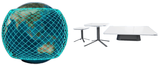
The constellation and terminal illustration below shows the dedicated ground equipment associated with broadband access. It is not a depiction of direct reception by an ordinary mobile phone. The historical orbit comparison below it highlights the original Kuiper altitude range and satellite target.
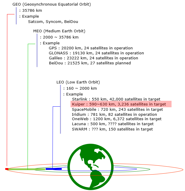
Inclination matters as much as altitude when comparing coverage. The 2019 design targets terrain overlap between approximately 56 degrees north and south. A low altitude does not by itself provide polar coverage. The D2D design adds higher-inclination options, including an 84-degree shell, as part of its proposed global mobile coverage architecture.
Satellite counts also need a clear denominator. In the original broadband table, multiplying planes by satellites per plane gives the total in each shell. In the D2D table, the listed positions are allowable orbital slots, and their sum exceeds the proposed number of satellites. Those slots must not be reported as simultaneously deployed spacecraft.
The color-coded altitude comparison later in this note uses nominal heights from these two attachments. It does not show operational tolerances, spacecraft phasing, collision avoidance or current deployment. For those purposes, the detailed orbital parameters and the applicable authorization conditions are needed.
Spectrum (Frequency and Bandwidth)
The original broadband link and the proposed D2D link have very different RF requirements. Broadband terminals use directional antennas and Ka-band frequencies. D2D service links use L/S-band frequencies, while their gateways still use Ka/V-band feeder links. A mobile device does not need to support every gateway band.
The earlier description of the Kuiper spectrum as simply 26.5–40 GHz was incomplete. The 2019 attachment includes downlinks below 20.2 GHz and uplinks between 27.5 and 30 GHz, divided by link purpose. Use the exact ranges below instead of a broad band-name convention.
Frequency span, channel bandwidth and subscriber speed are separate quantities. The 2019 design describes 100 MHz downlink channels and 50 MHz uplink channels, with aggregation options. It does not define 100 Mbps as a universal maximum for every customer or terminal. A shared beam's aggregate capacity cannot be assigned to every subscriber at once.
For D2D, the U.S. service-link request is much narrower: 1610–1618.725 MHz uplink and 2483.5–2500 MHz downlink. Additional overseas requests have separate conditions. The frequency tables and plots distinguish them from feeder links and avoid assigning a fixed direction to country-dependent SCS spectrum.
All quoted ranges are taken from the supplied technical attachments. They describe the application's RF plan; separate grants, waivers and national approvals determine the permitted operation.
Broadband System Summary - The 2019 Application
The original Kuiper design combines dedicated customer terminals, gateway sites, satellite control and a software-defined terrestrial network. The space segment provides broadband access and backhaul; the ground system coordinates satellite handover, frequency assignment and traffic routing. [K1]
Altitude | Inclination | Planes × satellites/plane | Satellites |
|---|---|---|---|
630 km | 51.9 degrees | 34 × 34 | 1,156 |
610 km | 42 degrees | 36 × 36 | 1,296 |
590 km | 33 degrees | 28 × 28 | 784 |
The three rows total 3,236 satellites in 98 planes. The first deployment phase described in the original note uses 578 satellites at 630 km; that phase count should not replace the complete 1,156-satellite shell population. Steerable spot beams and overlapping coverage support frequency reuse and alternate links during interference events.
Spectrum / RF Details
The following ranges preserve the user, gateway and TT&C separation in Tables 3, 5 and 6 of the 2019 appendix. Some adjacent ranges are separate entries because the filing treats their allocations separately. All values in this table are in GHz.
Link | Frequency ranges (GHz) |
|---|---|
User downlink | 17.7–18.6; 18.8–19.3; 19.3–19.4; 19.7–20.2 |
User uplink | 28.35–28.6; 28.6–29.1; 29.5–30.0 |
Gateway downlink | 17.7–18.6; 18.8–19.3; 19.3–19.7; 19.7–20.2 |
Gateway uplink | 27.5–28.6; 28.6–29.1; 29.1–29.5; 29.5–30.0 |
TT&C downlink | 19.25–19.4 |
TT&C uplink | 27.5–28.05 |
Table 4 limits the first principal user-downlink segment to 17.8–18.2 GHz within the United States, versus 17.7–18.2 GHz outside it. Other principal segments are 18.2–18.6 and 18.8–19.3 GHz. The broader table includes alternative choices for regional flexibility. The principal user-uplink discussion uses 28.5–29.1 GHz; that is distinct from the complete list of possible uplink bands.
User downlink channels are 100 MHz, aggregatable to 200–500 MHz. Uplink channels are 50 MHz, aggregatable up to 200 MHz. The design supports right- and left-hand circular polarization. Gateway links also use 100 MHz downlink and 50 MHz uplink channelization. TT&C occupied channels can be 1, 5, 10, 20 or 50 MHz, within the listed ranges. [K1], printed pages 23–26
Broadband uses dedicated terminals : this RF plan is not the 2026 mobile-device service link.Channel aggregation is not a speed guarantee : antenna gain, available spectrum and loading affect delivered throughput.
Amazon Leo D2D Summary - The 2026 Application
The 2026 attachment describes a separate constellation of up to 5,105 satellites serving mobile devices. It supplements the broadband system rather than replacing its terminals or frequencies. Proposed uses include emergency messaging, vehicle connectivity and industrial IoT. Optical inter-satellite links are intended to integrate the D2D and existing Amazon Leo systems. [K2]
Altitude | Inclination | Planes × slots/plane | Available orbital slots |
|---|---|---|---|
510 km | 56.3 degrees | 2,970 × 1 | 2,970 |
540 km | 84 degrees | 17 × 35 | 595 |
560 km | 58.2 degrees | 2,970 × 1 | 2,970 |
570 km | 73 degrees | 22 × 70 | 1,540 |
580 km | 55.7 degrees | 2,970 × 1 | 2,970 |
These rows define 11,045 orbital slots, but the proposed system ceiling remains 5,105 satellites. The table provides placement flexibility, not five simultaneously filled populations. The attachment gives a nominal operating life of six to eight years, depending on orbit, followed by active deorbiting.
Spectrum / RF Details
The service link reaches the mobile device in L/S-band. Gateways carry the aggregate traffic on Ka/V-band links. Table 2 of the application separates frequencies requested for both U.S. and international operation from additional frequencies requested only outside the United States.
Link | Inside and outside U.S. request | Additional outside-U.S.-only request |
|---|---|---|
Mobile downlink | 2483.5–2500 MHz | 1518–1525 MHz |
Mobile uplink | 1610–1618.725 MHz | 1618.725–1621.35 MHz; 1668–1675 MHz |
Mobile SCS | Not listed for U.S. use | 1427–2690 MHz; excludes overlap with the 1.6/2.4 GHz allocation; direction depends on local authorization |
Gateway downlink | 17.3–18.6; 18.8–20.2; 37.5–42.0; 42.0–42.5 GHz | None listed |
Gateway uplink | 27.5–30.0; 47.2–50.2; 50.4–51.4; 51.4–52.4 GHz | None listed |
TT&C downlink and beacon | 19.25–19.4; 40.0–40.1 GHz | None listed |
TT&C uplink | 27.5–28.05; 28.6–29.1; 47.2–47.3 GHz | None listed |
The application seeks waivers for gateway downlink at 42.0–42.5 GHz and uplink at 51.4–52.4 GHz. It also acknowledges that 2495–2500 MHz MSS operation is unprotected relative to non-Federal fixed and mobile users. International operation remains subject to country-specific rules. These qualifications must travel with the frequency list.
The service beams use vertical and horizontal polarization, with circular polarization possible when compatible with the mobile terminal. Ka/V links use left- and right-hand circular polarization. Table 3 specifies a 20-degree minimum elevation for mobile and gateway links and 5 degrees for TT&C. Its domestic MSS beam figures include 24.9–38.7 dBi transmit/receive gain and a maximum EIRP density of 53.0 dBW/MHz. These are satellite beam parameters, not mobile-device transmit power. [K2], printed pages 3–7
D2D, SCS and NTN interpretation
D2D here means direct-to-device, not terrestrial device-to-device sidelink. The application explicitly describes mobile satellite service links and additional overseas SCS requests. Those service categories do not by themselves identify a complete 3GPP radio protocol.
The reviewed sections do not establish a specific NR-NTN release, waveform, RRC configuration or supported handset list. Avoid inferring ordinary-phone compatibility solely from a frequency range. The filing also describes cooperation with Globalstar following completion of a then-pending transaction. That is the application's context, not a current transaction-status statement.
5,105 is the proposed system ceiling : do not add the orbital-slot rows and call the result a satellite population.Service and feeder links serve different devices : the mobile device uses the service band, while the gateway uses Ka/V-band.
Comparison between Broadband and D2D Systems
The two supplied documents describe different service architectures, not a clean Gen1/Gen2 hardware sequence. The main change is the endpoint: a directional broadband terminal in the 2019 design versus a mobile device in the 2026 D2D proposal.
Aspect | 2019 broadband design | 2026 D2D proposal |
|---|---|---|
Satellite total | 3,236 | Up to 5,105; 11,045 available slots |
Altitude | 590, 610, 630 km | 510, 540, 560, 570, 580 km |
Service link | Ka-band with dedicated customer antennas | L/S-band mobile service; additional overseas SCS request |
Gateway link | Ka-band | Ka-band and V-band |
Coverage design | Approximately 56 degrees north/south | Global mobile connectivity objective with higher-inclination options |
Terminal assumption | Phased-array or parabolic broadband terminal | Compatible mobile device; no universal handset claim established |
How to read the figures | 2019 application design | Separate 2026 application request |
Lower-frequency service links change antenna and propagation requirements, but they do not make D2D equivalent to a high-gain broadband terminal. The mobile service spectrum is much narrower than the feeder-link ranges. A larger feeder allocation cannot be interpreted as equally wide spectrum available to each phone.
Spectrum Bands - Color-Coded Comparison
Blue represents the 2019 broadband design and purple the 2026 D2D proposal. Every marker labels a listed frequency boundary. The mobile-service and high-frequency panels use different scales and units; their strip widths must not be compared directly.
Figure 1. Filing frequency ranges by service type and direction. The lower-frequency panel uses MHz; the other uses GHz. Colored spans represent requested ranges, not measured signal power or granted bandwidth.
The overseas SCS envelope of 1427–2690 MHz is deliberately not painted as a continuous uplink or downlink band. Its direction depends on national authorizations, and the filing excludes overlap with the 1.6/2.4 GHz allocation. The frequency table above retains this request with its qualifications. Overlapping broadband user, gateway and TT&C ranges share a lane; internal boundaries remain marked.
Orbital Altitude - Color-Coded Comparison
The altitude comparison uses one linear scale for both designs. Blue markers identify the original broadband shells; purple markers identify the five D2D placement options. Marker position represents height only, not satellite count, orbital inclination or current occupancy.
Figure 2. Nominal shell heights from the 2019 broadband and 2026 D2D attachments. The D2D slot table allows placement flexibility under a separate 5,105-satellite system ceiling.
The proposed D2D heights are lower than the original broadband heights, but height alone does not establish service quality. The systems also differ in antenna gain, spectrum, traffic and coverage objectives. Neither plot shows orbit-raising trajectories, operational tolerances, or a current in-orbit inventory.
FCC
The application records describe requested designs, while FCC orders establish authorization and conditions. The two local PDFs used here are applicant technical submissions. Their constellation counts and spectrum plans should not be treated as the current contents of a license.
Record | What it provides |
|---|---|
Original Ka-band broadband architecture, three-shell constellation and user/gateway/TT&C frequency plan. Reviewed source [K1]. | |
Historical initial authorization announcement retained from the original note. The order and subsequent modifications must be consulted for operating conditions. | |
Application record for the separate Amazon Leo D2D system. The supplied redacted Exhibit C describes 5,105 satellites, service/feeder bands, interference sharing and disposal plans. Reviewed source [K2]. |
FCC.report is a third-party filing mirror. An attachment there is evidence of what the applicant submitted, not proof that every requested band or waiver was granted. The numerical prefix repeated in the local 2026 filename does not make it the original 2019 attachment; the document itself is the D2D Exhibit C.
For a deployment decision, follow the official FCC record through the application, amendments, order, conditions and later modifications. Acceptance for filing and authorization are different steps. A satellite-system authorization also does not eliminate terminal licensing or country-specific service requirements. This section is a document guide rather than a complete current-status register.
YouTube
- Amazon Project Kuiper: Broadband internet small satellite network (Apr 2019)
- Introducing AWS Ground Station (May 2019)
- AWS Ground Station Overview (Jun 2019)
- Watch Blue Origin's New Shepard Rocket Launch and Land - NS-12 Mission (Dec 2019)
- FCC approves Amazon's project Kuiper which are low orbit satellites that will beam broadband access (Jul 2020)
- (#429) Amazon's Kuiper Approved to Compete with Starlink (Aug 2020)
- Project KUIPER: $10 BILLION Investment Enough to Beat SPACEX STARLINK? | Probably Not. (Aug 2020)
- How Amazon Plans to Compete With SpaceX's Starlink (Dec 2020)
- How Jeff Bezos Secretly Controls The Internet (Dec 2020)
Reference
- Project Kuiper - Amazon
- Everything you need to know about Project Kuiper, Amazon’s satellite broadband network - Amazon (Oct 2023)
- Amazon’s Project Kuiper will launch two satellites by Q4 2022 on ABL Space Systems' all-new RS1 rocket. - Amazon (2021)
- Kuiper Systems - Wikipedia
- Amazon's Kuiper satellite constellation will use these sleek antennas to serve you internet - SPACE (Mar 2023)
- Phasing Parameter Analysis for Satellite Collision Avoidance in Starlink and Kuiper Constellations - Researchgate (2021)
- Here’s your first look at Project Kuiper’s low-cost customer terminals - Amazone (2023)
- [K1] SAT-LOA-20190704-00057, Attachment 1773885: supplied 1773885_FCC_AmazonLEO_2019.pdf. Reviewed PDF pages 3–6 and 25–29 (printed pages 1–4 and 23–27), covering architecture, orbit table, frequency tables and channelization. This is not a full review of its interference annexes.
- [K2] SAT-LOA-20260601-00224, Exhibit C: Technical Attachment: supplied b5cebb55931e0b10667af79f68373c6f_1773885_FCC_AmazonLEO_TechnicalAttachment_2026.pdf. Reviewed PDF pages 4–10 (printed pages 1–7), including the 5,105-satellite ceiling, orbital-slot table, service/feeder spectrum and domestic beam parameters. Redacted public version; confidential material and full interference/disposal analyses were not reviewed.
- [A] Project Kuiper is now Amazon Leo: Amazon, 13 November 2025; naming update.