This page is to show you some intuitive understandings about MMSE equalization. The original matlab code for this page is written by James Weng. I just modified it a little bit to get the type of plots that I want to get and change the function definition a little bit so that I can specify Precoding Matrix and Channel Matrix as parameters.
You may refer to MMSE page for deriving the mathematical representation of MMSE.
- How to read each example
- Precoder and channel : Examples 01 to 06
- Modulation order and SNR : Examples 07 to 09
- The fnDemoMmse function
How to read each example
Every example on this page calls the same function with four arguments and produces the same four panels. Reading one figure carefully is therefore enough to read all nine of them.
The panels are arranged as follows.
- Tx QAM symbols, top left in blue. These are the symbols before anything is done to them, and this panel changes only when the QAM order changes.
- Tx QAM symbols after precoding, top right in red. This is the precoder output. A precoder that mixes the two layers puts sums of two symbols on each antenna, so this panel holds more points than the one beside it.
- Rx symbols, bottom left in red. This is what arrives at the two receive antennas, after the channel matrix and after the noise.
- Equalized symbols, bottom right in blue. This is the MMSE output, and the tightness of these clusters is what each example measures.
Watch the axis ranges as well as the shapes. Matlab rescales every panel to its own data, so the Rx panel often runs to plus or minus ten while the equalized panel runs to plus or minus two. A wider axis on the Rx panel does not mean a worse result.
Two settings stay the same in every run. The noise carries unit power per component and the signal is scaled up instead, so a higher snr argument makes the Rx panel wider rather than the noise smaller. The simulation uses 1000 symbols per layer, with two layers over two transmit and two receive antennas.
Precoder and channel : Examples 01 to 06
The first six runs hold the modulation at 4QAM and the SNR at 20 dB, and they change only the precoder and the channel matrix. Comparing them shows how much of the final cluster spread comes from mixing at the transmitter, and how much of it comes from mixing in the air.
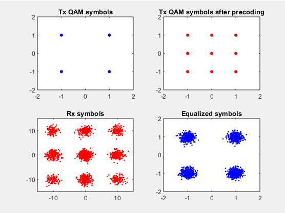
Example 01 uses the mixing precoder with an identity channel. The precoder puts the sum and the difference of two QPSK symbols on the two antennas, so the top right panel holds nine points on a three by three grid rather than four. The channel adds nothing, and the equalized clusters come back tight.
Example 01 > |
|
Precoder = 1/2 * [1 1;1 -1]; Channel = [1 0;0 1]; Qam = 4; snr = 20;
fnDemoMmse(Qam,snr,Channel,Precoder); |
|
|
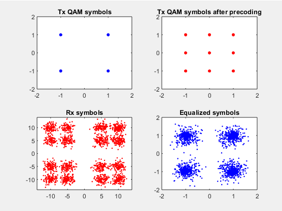
Example 02 changes the channel alone, to 0.5 on both off diagonal terms. The air now mixes the two antennas on top of the precoder's own mixing, so the Rx panel breaks each cluster into four. The equalized clusters are noticeably wider than in Example 01, and that widening is the noise cost that MMSE cannot remove.
Example 02 > |
|
Precoder = 1/2 * [1 1;1 -1]; Channel = [1 0.5;0.5 1]; Qam = 4; snr = 20;
fnDemoMmse(Qam,snr,Channel,Precoder); |
|
|
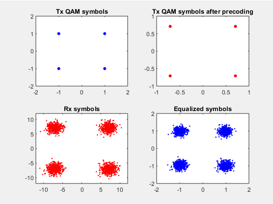
Example 03 replaces the mixing precoder with a scaled identity. Nothing is combined at the transmitter, so the top right panel shows the same four points as the top left, scaled down to plus or minus 0.7. The identity channel leaves them alone, which makes this the easiest case on the page.
Example 03 > |
|
Precoder = 1/sqrt(2) * [1 0;0 1]; Channel = [1 0;0 1]; Qam = 4; snr = 20;
fnDemoMmse(Qam,snr,Channel,Precoder); |
|
|
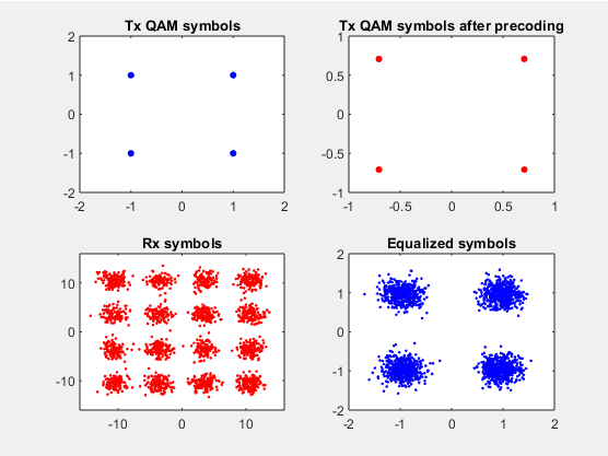
Example 04 keeps the identity precoder and restores the 0.5 channel. The Rx panel now shows sixteen blobs in a four by four arrangement, because each receive antenna carries a weighted sum of both symbols. The equalizer separates them again, at the same cost in cluster width seen in Example 02.
Example 04 > |
|
Precoder = 1/sqrt(2) * [1 0;0 1]; Channel = [1 0.5;0.5 1]; Qam = 4; snr = 20;
fnDemoMmse(Qam,snr,Channel,Precoder); |
|
|
Example 05 uses an asymmetric channel, with 0.5 above the diagonal and 0.2 below it. The top right panel of this run shows four precoded points rather than the nine that the listed precoder would give, so the figure and the parameter list disagree. Judged on its own, the run gives more diffuse Rx clusters than Example 04 and still separates cleanly after equalization.
Example 05 > |
|
Precoder = 1/2 * [1 1;1 -1]; Channel = [1 0.5;0.2 1]; Qam = 4; snr = 20;
fnDemoMmse(Qam,snr,Channel,Precoder); |
|
|
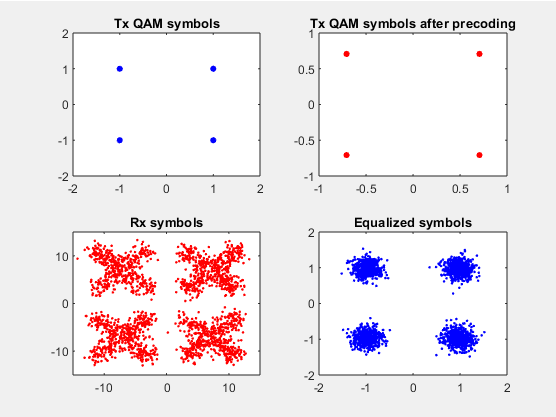
Example 06 uses the mildest channel on the page, 0.2 on both off diagonal terms. The Rx clusters stay clearly apart, and the equalized clusters come back almost as tight as with an identity channel. The precoder line in this cell carries a typing error, noted after the figure.
Example 06 > |
|
Precoder = 1/2 * [1 0;0 1]; Channel = [1 0.2;0.2 1]; Qam = 4; snr = 20;
fnDemoMmse(Qam,snr,Channel,Precoder); |
|
|
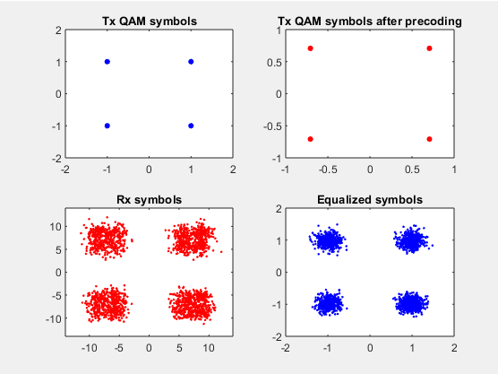
The precoder in the cell above was written as 1/2 * [1 0;01]. Matlab cannot read 01 as a row of two entries, so it is corrected here to [1 0;0 1]. The scale factor is a separate matter. The figure shows precoded points at plus or minus 0.7, which comes from 1/sqrt(2) rather than from 1/2, so the run behind the figure used the same precoder as Example 03.
Modulation order and SNR : Examples 07 to 09
The last three runs fix the precoder and the channel at the Example 01 settings and change the constellation instead. They ask a different question. Not how much the channel costs, but how much SNR a given constellation needs before MMSE can deliver it.
Example 07 raises the modulation from 4QAM to 16QAM and leaves everything else alone. The top left panel now holds sixteen points, and the precoded panel holds forty nine, because a sum of two values from a four level axis takes seven values. At 20 dB the sixteen equalized clusters are still separable, but they sit much closer together than the four clusters above.
Example 07 > |
|
Precoder = 1/2 * [1 1;1 -1]; Channel = [1 0;0 1]; Qam = 16; snr = 20;
fnDemoMmse(Qam,snr,Channel,Precoder); |
|
|
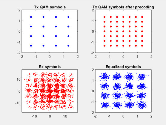
Example 08 uses 64QAM at the same 20 dB. The precoded panel holds a fifteen by fifteen grid, and the equalized panel shows no structure at all. The clusters have merged into one solid block, so the receiver cannot decide which symbol was sent.
Example 08 > |
|
Precoder = 1/2 * [1 1;1 -1]; Channel = [1 0;0 1]; Qam = 64; snr = 20;
fnDemoMmse(Qam,snr,Channel,Precoder); |
|
|
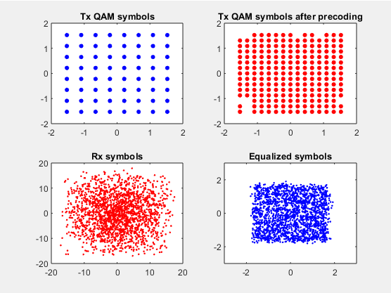
Example 09 repeats that run with the SNR raised to 30 dB. Nothing else changes.
Example 09 > |
|
Precoder = 1/2 * [1 1;1 -1]; Channel = [1 0;0 1]; Qam = 64; snr = 30;
fnDemoMmse(Qam,snr,Channel,Precoder); |
|
|
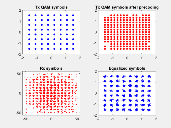
The eight by eight grid returns, with the clusters separated again. Comparing the last two figures gives the practical rule directly. The available SNR decides which constellation a link can carry, and no equalizer creates SNR that the link never delivered. MMSE separates the layers. It does not raise the modulation order that the noise allows.
The fnDemoMmse function
The listing below is the function that every example calls. Three of its lines carry the whole of MMSE, and the rest generates the symbols and draws the panels. Those three lines match the equation on the MMSE page directly.
|
fnDemoMmse.m |
|
function [dummy] = main(m_qam, snr_dB,H,P) % Demonstrate MMSE equalization % Inputs: % m_qam: QAM level. Square QAM only. % Default = 16QAM. % snr_dB: SNR per symbol in dB. % Default = 20dB;
dummy = 0;
if (nargin < 1) m_qam = 16; end if (nargin < 2) snr_dB = 20; end
m_pam_i = floor(sqrt(m_qam + 1e-3)); % compute square root of QAM m_pam_q = m_qam / m_pam_i;
sig_amp = sqrt(10^(snr_dB/10)); % Signal amplitude
n_sym_per_layer= 1000; % Number of symbols per layer to simulate
n_layers = 2; % Number of layers n_tx_ant = 2; % Number of Tx antennas n_rx_ant = 2;
rand('state', 3200); % set random generator state
% Transmitted symbols with normalized power m_pwr = (m_qam - 1) / 3; % average QAM power v_tx_sym = sqrt(1/m_pwr) * fnGenQam(m_pam_i, m_pam_q, n_layers, n_sym_per_layer);
v_tx_sym_precoded = P * v_tx_sym; % symbols after precoding
% Received signal + noise (normalized power). v_noise = randn(n_rx_ant, n_sym_per_layer) + 1i * randn(n_rx_ant, n_sym_per_layer); v_R = sig_amp * H * v_tx_sym_precoded + v_noise; % Each column is a vector of R for the received signal vector
% MMSE equalizer. Assuming sig_amp, H, and P are known G = sig_amp * H * P; I = eye(n_rx_ant); F = G' * inv(G * G' + I);
% Equalized symbols v_Y = F * v_R;
figure(101); subplot(2,2,1); plot(real(v_tx_sym), imag(v_tx_sym), 'bo','MarkerFaceColor',[0 0 1],'MarkerSize',4); iq_max = ceil( 1.1*max(real(reshape(v_tx_sym,1,[])))); axis([-iq_max iq_max -iq_max iq_max]); title('Tx QAM symbols');
subplot(2,2,2); plot(real(v_tx_sym_precoded), imag(v_tx_sym_precoded), 'ro','MarkerFaceColor',[1 0 0],'MarkerSize',4); iq_max = ceil( 1.1*max(real(reshape(v_tx_sym_precoded,1,[])))); axis([-iq_max iq_max -iq_max iq_max]); title('Tx QAM symbols after precoding');
subplot(2,2,3); plot(real(v_R), imag(v_R), 'r.'); iq_max = ceil( 1.1*max(real(reshape(v_R,1,[])))); axis([-iq_max iq_max -iq_max iq_max]); title('Rx symbols');
subplot(2,2,4); plot(real(v_Y), imag(v_Y), 'b.'); iq_max = ceil( 1.1*max(real(reshape(v_Y,1,[])))); axis([-iq_max iq_max -iq_max iq_max]); title('Equalized symbols');
% -------------------------------------------------------------------------------------- % Generate QAM symbols function v_qam = fnGenQam(pam_i, pam_q, nx, ny) v_qam= fnGenPam(pam_i, nx, ny) + 1i * fnGenPam(pam_q, nx, ny);
% Generate PAM symbols function v_pam = fnGenPam(pam, nx, ny) v_pam = rand(nx, ny) * pam; v_pam = 2 * ceil(v_pam) - 1 - pam;
|
- G = sig_amp * H * P folds the SNR scaling, the channel and the precoder into one effective channel. This is the matrix the equalizer actually works against.
- F = G' * inv(G * G' + I) is the MMSE weight itself. The identity term stands in for the noise covariance, because the noise in this simulation already carries unit power per component.
- v_Y = F * v_R applies that weight to the received vector and produces the bottom right panel.
Two details are worth knowing before running it. The SNR is set by sig_amp = sqrt(10^(snr_dB/10)), which scales the signal up rather than scaling the noise down, and that is why the Rx axis grows as the snr argument grows. The script also seeds rand but not randn, so the symbol pattern repeats between runs while the noise does not. A rerun therefore gives figures close to the ones above rather than identical to them.