|
|
||
|
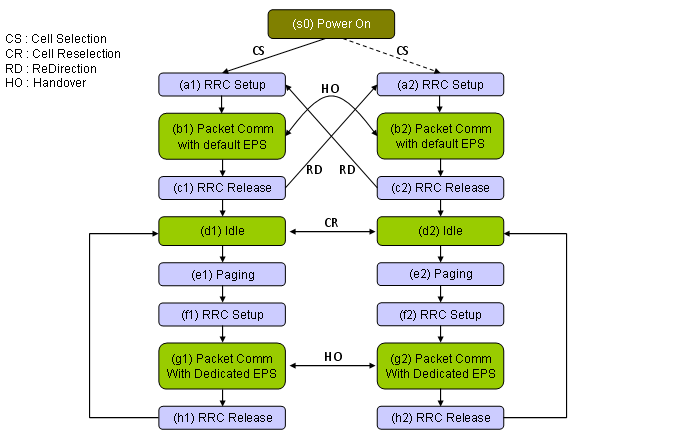
Basic State MachineFollowing diagram shows a possible state machine that a UE would go through. The state transition in this post will be about (s0)->(a)-> (b1) -> (c1) -> (d1) -> (e1) -> (f1) -> (g1) -> (h1). Most of other transition will be described in "Handover" page.
Note : Intial Registration and Default EPS Bearer Setup procedure would be common to almost all LTE network. Of course, there would be a small variations but overall concept would be almost same. But the procedure after <Idle> would be quite different among Network Operators. Following would be two major variations.
The example test sequence in this case shows the second case,
|
||