|
Channel Mapping in Call Processing
This note will talk about channel mapping mainly between logical channel and physical channels in LTE, and how those mappings are applied at each stages of signaling in call processing.
Depending on which level you are working on in UE development/Test procedure, the amount of knowledge you need to know would be different. But I think there are a couple of big pictures that may help almost anybody working in full protocol stack.
First big picture I would like to introduce is the channel mapping as shown below. Just try to pick any RRC messages and try to follow the arrow for the message. If you read those pages about MAC and RLC, it will remind you of a lot of detailed information.
Overall Sequence and Layer Mapping
Following is a sequence diagram showing not only the message but also basic configurations of each layer. More detailed description of each layer in the context of full protocol stack will be explained in "Full Stack" section.
Just read through this sequence whenever you have time until you can duplicate the sequence without looking into this again. This can be a good framework for your study and good guide for troubleshooting.
|
Step
|
Direction
|
Channel
|
Message
|
|
1
|
UE <---- NW
|
BCCH -> BCH,
No MAC Header, RLC TM, No PDCP
|
MIB
|
|
2
|
UE <---- NW
|
BCCH -> DL SCH,
No MAC Header, RLC TM, No PDCP
|
SIBs
|
|
3
|
UE ----> NW
|
PRACH -> RACH,
No MAC Header, No RLC, No PDCP
|
PRACH Preamble
|
|
4
|
UE <---- NW
|
RACH -> DL SCH,
No MAC Header, No RLC, No PDCP
|
RACH Response
|
|
5
|
UE ----> NW
|
UL SCH -> UL CCCH
MAC Header, No RLC, No PDCP
|
RRC Connection Request
|
|
6
|
UE <---- NW
|
DL CCCH -> DL SCH
MAC Header, No RLC, No PDCP
|
RRC Connection Setup
|
|
7
|
UE ----> NW
|
UL SCH -> UL DCCH
MAC Header, RLC AM, PDCP
|
RRC : RRC Connection Setup Complete +
NAS : Attach Request (ESM:PDN Connectivity Request)
|
|
8
|
UE <---- NW
|
DL DCCH -> DL SCH
MAC Header, RLC AM, PDCP
|
RRC : dlInformationTransfer
EMM : Authentication Request
|
|
9
|
UE ----> NW
|
UL SCH -> UL DCCH
MAC Header, RLC AM, PDCP
|
RRC : ulInformationTransfer
EMM : Authentication Response
|
|
10
|
UE <---- NW
|
DL DCCH -> DL SCH
MAC Header, RLC AM, PDCP
|
RRC : dlInformationTransfer
EMM : Security Mode Command
|
|
11
|
UE ----> NW
|
UL SCH -> UL DCCH
MAC Header, RLC AM, PDCP
|
RRC : ulInformationTransfer
EMM : Security Mode Complete
|
|
12
|
UE <---- NW
|
DL DCCH -> DL SCH
MAC Header, RLC AM, PDCP
|
RRC : Security Mode Command
|
|
13
|
UE ----> NW
|
UL SCH -> UL DCCH
MAC Header, RLC AM, PDCP
|
RRC : Security Mode Complete
|
|
14
|
UE <---- NW
|
DL DCCH -> DL SCH
MAC Header, RLC AM, PDCP
|
RRC : RRC Connection Reconfiguration
EMM : Attach Accept
ESM : Activate Default EPS Bearer Context Request
|
|
15
|
UE ----> NW
|
UL SCH -> UL DCCH
MAC Header, RLC AM, PDCP
|
RRC : RRC Connection Reconfiguration Complete
|
|
16
|
UE ----> NW
|
UL SCH -> UL DCCH
MAC Header, RLC AM, PDCP
|
RRC : ulDirectTransfer
EMM : Attach Complete
ESM : Activate Default EPS Bearer Context Accept
|
|
17
|
UE <---- NW
|
DL DCCH -> DL SCH
MAC Header, RLC AM, PDCP
|
RRC : RRC Connection Release
|
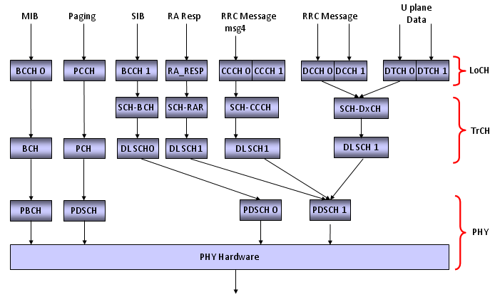
Downlink Channel Map
The diagram you saw above a kind of message flow(event diagram) in time sequence. The diagram shown below is not a time based, but it shows the channel mapping (or data flow across the full protocol stack). Pick one of the message from the diagram shown above and try to find right route for this digram and see how much details you can add.
For example, if you picked the message "RRC Connection Setup", the start point would be "RRC Message msg4".
Following is a tabular presentation of DL Channel Map. (LCID and TrCH Number would be different depending on the network or Network Simulator)
|
RB
|
Lo CH
|
PDCP
|
RLC
|
Lo CH
|
LCID
|
MAC Hdr
|
HARQ
|
RNTI
|
Tr CH
|
|
|
PCCH
|
|
TM
|
PCCH
|
N/A
|
NONE
|
NONE
|
NONE
|
PCH
|
| |
BCCH 0
|
|
TM
|
BCCH 0
|
N/A
|
NONE
|
NONE
|
NONE
|
BCH 0
|
| |
BCCH 1
|
|
TM
|
BCCH 1
|
N/A
|
NONE
|
Broadcast
|
SI RNTI
|
DL SCH 0
|
| |
RA_RES
|
|
TM
|
RA_RES
|
N/A
|
NONE
|
NONE
|
RA RNTI
|
DL SCH 1
|
|
SRB0
|
DL CCCH
|
USED
|
TM
|
DL CCCH
|
0
|
NONE
|
NORMAL
|
T-CRNTI
|
DL SCH 1
|
|
SRB1
|
DL DCCH 0
|
USED
|
AM
|
DL DCCH 0
|
1
|
NORMAL
|
NORMAL
|
CRNTI
|
DL SCH 1
|
|
SRB2
|
DL DCCH 1
|
USED
|
AM
|
DL DCCH 0
|
2
|
NORMAL
|
NORMAL
|
CRNTI
|
DL SCH 1
|
|
DRB 0
|
DL DTCH0
|
USED
|
UM/AM
|
DL DTCH0
|
3
|
NORMAL
|
NORMAL
|
CRNTI
|
DL SCH 1
|
|
DRB 1
|
DL DTCH1
|
USED
|
UM/AM
|
DL DTCH1
|
4
|
NORMAL
|
NORMAL
|
CRNTI
|
DL SCH 1
|
|
DRB 2
|
DL DTCH2
|
USED
|
UM/AM
|
DL DTCH2
|
5
|
NORMAL
|
NORMAL
|
CRNTI
|
DL SCH 1
|
Uplink Channel Map
Following is a tabular presentation of DL Channel Map. (LCID and TrCH Number would be different depending on the network or Network Simulator)
|
RB
|
Lo CH
|
PDCP
|
RLC
|
Lo CH
|
LCID
|
MAC Hdr
|
HARQ
|
RNTI
|
Tr CH
|
| |
RA_PRE
|
|
TM
|
RA_PRE
|
N/A
|
NONE
|
NONE
|
NONE
|
UL SCH 0
|
|
SRB0
|
UL CCCH
|
USED
|
TM
|
UL CCCH
|
0
|
NONE
|
NORMAL
|
T-CRNTI
|
UL SCH 0
|
|
SRB1
|
UL DCCH 0
|
USED
|
AM
|
UL DCCH 0
|
1
|
NORMAL
|
NORMAL
|
CRNTI
|
UL SCH 0
|
|
SRB2
|
UL DCCH 1
|
USED
|
AM
|
UL DCCH 0
|
2
|
NORMAL
|
NORMAL
|
CRNTI
|
UL SCH 0
|
|
DRB 0
|
UL DTCH0
|
USED
|
UM/AM
|
UL DTCH0
|
3
|
NORMAL
|
NORMAL
|
CRNTI
|
UL SCH 0
|
|
DRB 1
|
UL DTCH1
|
USED
|
UM/AM
|
UL DTCH1
|
4
|
NORMAL
|
NORMAL
|
CRNTI
|
UL SCH 0
|
|
DRB 2
|
UL DTCH2
|
USED
|
UM/AM
|
UL DTCH2
|
5
|
NORMAL
|
NORMAL
|
CRNTI
|
UL SCH 0
|
This is only an example case and Mapping (especiall LoCH No) can vary depending on situations. The point is that it will be really helpful for your troubleshooting or test case creation if you create this kind of table for your case.
|
Message
|
RB
|
Lo CH
|
LoCH No
|
LCID
|
|
MIB
|
-
|
BCCH
|
0
|
-
|
|
SIB 1
|
-
|
BCCH
|
1
|
-
|
|
SIB 2
|
-
|
BCCH
|
1
|
-
|
|
RRC : PRACH Preamble
|
-
|
-
|
-
|
-
|
|
RRC : RACH Response
|
-
|
-
|
-
|
-
|
|
RRC : RRC Connection Request
|
SRB0
|
UL CCCH
|
0
|
0
|
|
RRC : RRC Connection Setup
|
SRB0
|
DL CCCH
|
0
|
0
|
|
RRC : RRC Connection Setup
Complete + NAS : Attach Request + ESM : PDN Connectivity Request
|
SRB1
|
UL DCCH
|
0
|
1
|
|
RRC : DL Information Transfer
+ NAS : Authentication Request
|
SRB1
|
DL DCCH
|
0
|
1
|
|
RRC : UL Information Transfer
+ NAS : Authentication Response
|
SRB1
|
UL DCCH
|
0
|
1
|
|
RRC : DL Information Transfer
+ NAS : Security Mode Command
|
SRB1
|
DL DCCH
|
0
|
1
|
|
RRC : UL Information Transfer
+ NAS : Security Mode Complete
|
SRB1
|
UL DCCH
|
0
|
1
|
|
RRC : Security Mode Command
|
SRB1
|
DL DCCH
|
0
|
1
|
|
RRC : Security Mode Complete
|
SRB1
|
UL DCCH
|
0
|
1
|
|
RRC : RRC Connection
Reconfiguration
|
SRB1
|
DL DCCH
|
0
|
1
|
|
RRC
: RRC Connection Reconfiguration Complete
|
SRB1
|
UL DCCH
|
0
|
1
|
|
RRC
: UL InformationTransfer + NAS : Attach Complete + NAS : Activate Default EPS
Bearer
|
SRB2
|
UL DCCH
|
1
|
2
|
|
RRC : UL Information Transfer
+ ESM : PDN Connectivity Request
|
SRB2
|
UL DCCH
|
1
|
2
|
Note : Refer to TS 36.331 - 9.1.1 Logical channel configurations
Following sequence is an example of signaling messages during the initial attach procedure and internal configurations that would happen within eNB. These internal configuration is just an example and it would vary depending on eNB hardware vendor.
Config 1) Activate Cell Physicall Layer
1) MIB
Config 2) Activate PHY, MAC, RLC for SIB Transmission (BCCH-DL DSCH)
2) SIB 1
3) SIB 2
Config 3) Configure PHY, MAC for PRACH Reception and RACH Response Transmission
4) RRC : PRACH Preamble
5) RRC : RACH Response
Config 3) Configure PHY, MAC, RLC for Msg3 (RRC Connection Request) Reception (UL-CCCH)
6) RRC : RRC Connection Request
Config 4) Configure MAC, RLC, PDCH for DL DCCH, UL DCCH
7) RRC : RRC Connection Setup
8) RRC : RRC Connection Setup Complete + NAS : Attach Request + ESM : PDN Connectivity Request
9) RRC : DL Information Transfer + NAS : Authentication Request
10) RRC : UL Information Transfer + NAS : Authentication Response
11) RRC : DL Information Transfer + NAS : Security Mode Command
12) RRC : UL Information Transfer + NAS : Security Mode Complete
Config 5) Configure PDCP for Integrity, Ciphering (We may disable Integiry/Ciphering for some test environment)
13) RRC : Security Mode Command
14) RRC : Security Mode Complete
15) RRC : RRC Connection Reconfiguration + NAS : Attach Accept + NAS : Activate Default EPS Bearer Context Req
Config 6) Configure MAC, RLC, PDCP for DL/UL DTCH+DCCH
16) RRC : RRC Connection Reconfiguration Complete + NAS : Attach Complete + NAS : Activate Default EPS Bearer Context Accept
17) RRC : RRC Connection Release
Config 7) Deactivate all the channels related to DCCH, DTCH
Config 8) Activate channels for PCCH
< MO or MT call > : In MT call, Paging should be sent.
Config 9) Configure PHY, MAC for PRACH Reception and RACH Response Transmission
18) RRC : PRACH Preamble
19) RRC : RACH Response
Config 10) Configure PHY, MAC, RLC for Msg3 (RRC Connection Request) Reception (UL-CCCH)
20) RRC : RRC Connection Request
Config 11) Configure MAC, RLC, PDCH for DL DCCH, UL DCCH
21) RRC : RRC Connection Setup
22) RRC : RRC Connection Setup Complete + NAS : Service Request
23) RRC : Security Mode Command
24) RRC : Security Mode Complete
25) RRC : RRC Connection Reconfiguration + NAS : Activate Dedicated EPS Bearer Context Request
Config 12) Configure MAC, RLC, PDCP for DL/UL DTCH+DCCH
26) RRC : RRC Connection Reconfiguration Complete + NAS : Activate Dedicated EPS Bearer Context Accept
27) RRC : RRC Connection Release
|