|
|
|||||||||||||||||||||||||||||||||||||||||||||||||||||||||||||||||||||||||||||||||||||
|
In 5G NR, uplink (UL) Tx-antenna switching is a feature that lets a UE dynamically move its two physical transmitter chains between different uplink carriers, so it can momentarily send two-layer MIMO on a capacity-focused band and then swing one chain back to a coverage-focused band when high throughput is no longer required. Instead of keeping each power amplifier permanently tied to a specific carrier—as older LTE devices do—the NR UE follows rules signalled once by RRC (how long the retune gap may be, which carriers form the pair, and where in the slot the hop must occur) and then automatically inserts a very short mute-and-retune pause whenever the scheduler directs the next PUSCH, PUCCH, or SRS grant to the opposite carrier. This approach squeezes extra uplink capacity out of the same two-Tx hardware budget, saves power by activating both chains only when needed, and gives operators flexibility to blend wide-band mid-/high-band performance with low-band coverage in real time.
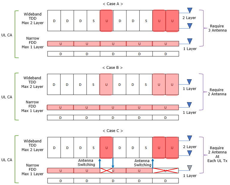
Why UL TxSwitching ?When a 5 G handset aggregates a wide-band TDD carrier that can exploit two-layer MIMO with a narrow, low-frequency FDD carrier that needs only a single layer, engineers face a trade-off between hardware complexity and uplink performance. For illustration of why we came up with the concept called UL Tx stiching, let's think of three different cases of operating UL CA with a narrowband FDD and windband TDD band as shown below. These three cases visualise the hardware dilemma a handset faces when it is doing uplink carrier aggregation (UL-CA) between a coverage carrier (a narrow-band, low-frequency FDD cell that needs at most one UL layer) and a capacity carrier (a wide-band, mid/high-frequency TDD cell that can exploit two UL layers)
Keeping a dedicated transmitter chain on each carrier while adding a third chain for the second TDD layer would maximise throughput, but such a three-PA design is expensive, power-hungry and impractical for modern smartphones. Conversely, fixing one chain per carrier and restricting the TDD cell to a single layer preserves the two-PA budget but sacrifices half of the wide-band carrier’s potential capacity. UL Tx-antenna switching offers a middle ground: the UE time-shares its two transmit chains, momentarily moving both to the TDD carrier whenever the scheduler needs a two-layer burst, then returning one chain to the FDD carrier for routine coverage. This mechanism unlocks near-ideal high-band uplink peaks without adding hardware, all at the cost of brief, carefully timed transmission gaps on the low-band link. This situation can be summarized in a table shown below. It shows why Case C (UL Tx Switching) is the most practical option.
Why the feature is attractive
Release EvolutionThe UL Tx Switching functionality has been evolved over a few releases starting from Rel 16 through Rel 18. It did not appear as a fully complete feature in a single release. It was introduced in Release 16 as a practical solution to a common UE hardware limitation in uplink carrier aggregation and SUL, where a 2Tx UE could not keep one uplink active on a coverage carrier while also performing 2-layer uplink MIMO on a capacity carrier at the same time. Release 17 then expanded the same switching concept to handle more realistic deployment combinations, including broader carrier aggregation configurations and switching across additional carrier types so the network could steer the limited 2Tx capability to where it delivers the most benefit. Release 18 refined the framework further to make it more deployable in real networks by adding more granular per-band-combination capability reporting, tightening timing and downlink interruption rules so control/data reception stays reliable during frequent switching, and clarifying edge-case behaviors and conformance scenarios so multi-carrier scheduling around switching gaps becomes deterministic and interoperable.
Release 16: Baseline 1Tx→2Tx switchingRelease 16 introduced Uplink Tx Switching to solve a very practical UE hardware limitation in Uplink CA and SUL. In many deployments, you want to use a low-band FDD carrier as a coverage uplink while also using a high-band TDD carrier as a capacity uplink. The problem is that a typical UE has only two uplink RF transmit chains (2Tx). If the UE tries to keep uplink active on the low-band FDD carrier (1Tx) and at the same time transmit 2-layer UL MIMO on the high-band TDD carrier (2Tx), it would effectively need 3Tx in total. A 2Tx UE cannot do that. Rel-16 solves this by standardizing a switching behavior instead of requiring extra hardware. The UE can temporarily suspend uplink transmission on the low-band FDD carrier, retune/reallocate its RF chain resources, and then transmit a burst of 2-layer UL MIMO on the wide-band TDD carrier. After the burst, it can switch back to resume the low-band FDD uplink. This gives operators a useful balance: they keep the low-band layer for coverage most of the time, but still get high peak uplink throughput from TDD MIMO when it matters, without forcing UEs to add a third power amplifier. This is not left to vendor interpretation. The band-pair rules, the switching period (the interruption gap while the UE retunes), and the exact symbol-boundary alignment for the gap are all defined in the 3GPP specifications, mainly across TS 38.101-1 (RF requirements), TS 38.133 (RRM and switching timing), and TS 38.214 (physical layer procedures). Followings are the bulleted summary of Release 16 UL Tx Switching
Release 17: Enhanced Uplink Tx Switching & 3CC SupportRelease 17 expanded Uplink Tx Switching from a “special-case workaround” into a more general multi-carrier uplink tool. In Release 16, the main focus was a simple mixed-duplex situation, where a UE temporarily paused one uplink carrier so it could reuse its limited transmit chains to enable a short 2-layer uplink burst on another carrier. Release 17 kept the same core idea, but it widened the number of carrier types and carrier combinations where this dynamic 1Tx ↔ 2Tx behavior can be applied. A key step was adding support for switching between two TDD carriers, such as n77 and n79. With this, a 2Tx UE is no longer forced to treat only one carrier as the “fixed” 2-layer MIMO carrier. Instead, the UE can steer its 2Tx capability to whichever TDD band is most beneficial at that moment, depending on scheduler decisions, load, and radio conditions, and then switch again when the situation changes. Release 17 also extended the framework to more complex carrier aggregation configurations, including three-component-carrier setups. This means the UE can stay connected to three bands at once, for example a low-band FDD layer for robust coverage plus two TDD layers for capacity. The UE does not magically become a 3Tx device. The gain comes from being able to move the same limited transmit chains across a larger set of carriers, so the network can opportunistically place uplink throughput bursts where they deliver the most spectral efficiency. To make this switching usable for scheduling in real time, Release 17 strengthened the reference-signal side as well. The specification improved SRS carrier switching so the UE can transmit SRS on the target carrier immediately after switching. This is important because the gNB needs fresh uplink channel knowledge on the target carrier to confidently schedule the upcoming 2-layer burst. Without fast SRS availability, the network would be “switching blind” and the throughput benefit would be harder to realize. Release 17 also refined uplink power control behavior for the switching case. When the UE transitions from 1-port to 2-port transmission, the power-control procedures were updated so the UE can properly handle the 2Tx transmission state. In practice, using coherent 2Tx behavior or high-power UE modes can give roughly a +3 dB effective radiated power improvement on the target carrier, which helps uplink SINR especially near the cell edge, and makes the burst more reliable. Because these Release 17 behaviors involve more carriers, tighter timing, and state transitions in both reference signals and power, the standards work required more than just a few PHY rules. It introduced new RRC information support and updated UE requirement signaling definitions, including the capability and requirement aspects described in TS 38.307, so the network can validate and configure these more complex multi-carrier timing and power transitions consistently. Followings are the bulleted summary of Release 17 UL Tx Switching
Release 18: Enhanced Granularity & RobustnessRelease 18 turns Uplink Tx Switching into a more mature and deployment-safe capability by fixing the two things that usually break “nice features” in the field: coarse capability signaling and ambiguous behavior at timing edges. In earlier releases, the network often had to treat Tx switching as a broadly supported feature or not supported at all, even though real UE RF designs are combination dependent. A UE might be able to switch cleanly between one low/mid band pair but fail to do the same on another pair because the front-end routing, duplexers, or PA sharing is different. Release 18 addresses this by introducing more granular capability reporting, so the UE can declare Tx switching support per band combination and can indicate which switching mode it supports for that specific combination, such as Option 1 (1Tx ↔ 2Tx) or Option 2 (2Tx ↔ 1Tx). This immediately makes network configuration more practical because the operator can enable Tx switching where it truly works, instead of being blocked by a single unsupported pair. Once switching becomes more widely usable, the next real-world risk is that uplink retuning disturbs downlink reception. Even though the feature is “uplink”, shared oscillators and settling behavior can create short intervals where the UE is effectively blind to downlink. If the rules are loose, the UE may over-protect itself by declaring large downlink interruption windows, and the scheduler then wastes downlink capacity out of caution. Release 18 tightens and clarifies downlink interruption masks so the allowable “blind” region is limited and better aligned to the actual switching gap, which helps keep PDCCH and PDSCH reception reliable even under frequent switching. This is especially important when the network is trying to operate with low latency and frequent scheduling decisions, where repeated blind windows would otherwise cause control channel misses and throughput instability. With capability and downlink reliability handled more precisely, the last step is to remove undefined behavior during the awkward corner cases that happen when the scheduler pushes the system hard. Release 18 strengthens conformance and interoperability by clarifying test scenarios and expected UE behavior when grants overlap around a switch, when FR2 carriers are involved, and when reference signals and data collide with the switching gap. In particular, SRS and PUSCH collisions need deterministic handling because the UE may not have time to switch and satisfy both transmissions; Release 18 makes these timing overlaps less ambiguous so the UE behavior remains predictable and the network does not have to guess. Overall, these updates make Tx switching less of a fragile “special feature” and more of a robust tool that operators can deploy across many carrier combinations without sacrificing downlink reliability or interoperability. Followings are the bulleted summary of Release 18 UL Tx Switching
Comparision to SULIn Release 15, 3GPP introduced “Supplemental Uplink” as a way to borrow uplink capacity from an FDD band whenever a TDD cell had downlink-only subframes. At a high level, the network configures the UE so that during the TDD cell’s DL slots—when it normally can’t send uplink—it instead fires its FDD transmitter on the companion band. From the UE’s perspective this requires either one or two RF chains: if it has two it could even split them between the FDD and TDD UL subframes. Because the FDD UL band typically uses 15 kHz subcarriers (versus 30 kHz in TDD), the supplemental link is narrower, so throughput gain is modest; on the other hand there is no RF retune delay, since each chain stays locked to its native band at all times. Switched Uplink, which landed in Release 16, takes a more aggressive approach. Rather than permanently pinning one RF chain to each band, the UE momentarily “hops” both chains onto the high-band TDD carrier whenever the scheduler wants a two-layer MIMO burst, then returns one chain to the FDD carrier for coverage. This time-sharing lets the device deliver up to two full MIMO layers on the wide-band TDD link—roughly doubling peak UL throughput—while still preserving low-band coverage the rest of the time. The only trade-off is a short mute-and-retune gap (tens to a few hundred microseconds) each time the UE switches, which Release 16 bounds tightly and which later Releases refine further. The comparison between SUL and UL Tx Switching is summarized in table as shown below (source : 2023 Switched Uplink in 5G-NR: Benefit & Deployment Consideration )
How actual switching is triggered ?In NR uplink switching, the fundamental rule has been consistent from Rel-16 to Rel-18. There is no explicit “Switch Now” command in any DCI format. The network never sends a dedicated bit for switching. The UE switches only because the gNB schedules the UE to transmit on a specific band. In Rel-16 and Rel-17, the logic stays simple because the UE usually deals with only two bands. The UE stays active on Band A, receives a UL grant for Band B, and then switches its RF chain to Band B before the scheduled slot. The UE inserts a short switching gap based on RRC configuration, and the gNB avoids scheduling uplink symbols inside that window. Everything is predictable and tightly bounded. Rel-18 keeps the same basic idea. The trigger is still the uplink grant. The DCI still has no explicit switching field. However, Rel-18 extends the scenario to three or four simultaneous bands. This makes the switching more complex because a switch from Band A to Band B may affect another configured band such as Band C. The UE uses new Rel-18 capabilities, especially uplinkTxSwitchingPeriodOnUnaffectedBand-r18, to report whether RF retuning for two bands can disturb uplink activity on other bands. When the UE receives a grant for Band B, it checks this capability, inserts the required silence gap, and prepares the new RF chain. The gNB must avoid scheduling not only on the switching band but also on any unaffected band that may be disturbed during the switching moment. As a result, Rel-18 still follows the same core principle of implicit switching but extends it into a multi-band environment where the scheduler must protect additional bands during the retuning window.
UE Capability InformationBefore gNB decide whether to apply UL Tx Switching or not, the UE should advertises the feature in UE-NR-Capability. Followings are the list of UE capability Information that a UE would notify. Band-pair level IEs (Per = BC)
Band-specific detail IE (Per = BC)
RRC ParametersWhen a gNB configures a handset for dynamic uplink antenna switching, it uses a handful of specialized information elements to control exactly how and when the UE moves its transmit chains between carriers. The uplinkTxSwitchingOption tells the device whether to perform a one-to-two-chain burst or a full two-to-two-chain handover, while the optional uplinkTxSwitchingPowerBoosting flag lets the network grant a temporary 3 dB boost on the secondary carrier during a two-port transmission. For pure two-chain handoffs, the uplinkTxSwitching-2T-Mode IE ensures the mute-and-retune gap matches the UE’s reported dual-Tx timing, falling back to single-to-dual-Tx rules only if it’s absent. In Release 18, the uplinkTxSwitching-DualUL-TxState field disambiguates the post-switch Tx-chain count when two-chain mode is in use, and the new uplinkTxSwitchingMoreBands container extends the basic pair-of-bands model to larger CA/SUL groupings. Together, these parameters give the gNB precise, per-scenario control over the UE’s UL-antenna behavior UplinkConfig ::= SEQUENCE { ... uplinkTxSwitching-r16 SetupRelease { UplinkTxSwitching-r16 } OPTIONAL, -- Need M ... }
UplinkTxSwitching-r16 ::= SEQUENCE { uplinkTxSwitchingPeriodLocation-r16 BOOLEAN, uplinkTxSwitchingCarrier-r16 ENUMERATED {carrier1, carrier2} }
UplinkTxSwitchingMoreBands-r18::= SEQUENCE { uplinkTxSwitchingBandList-r18 SEQUENCE (SIZE (1..maxSimultaneousBands)) OF FreqBandIndicatorNR OPTIONAL, -- Need M uplinkTxSwitchingBandPairList-r18 UplinkTxSwitchingBandPairList-r18 OPTIONAL, -- Need M uplinkTxSwitchingAssociatedBandDualUL-List-r18 UplinkTxSwitchingAssociatedBandDualUL-List-r18 OPTIONAL, -- Need M ... }
UplinkTxSwitchingBandPairList-r18::= SEQUENCE (SIZE (1.. maxULTxSwitchingBandPairs)) OF UplinkTxSwitchingBandPairConfig-r18
UplinkTxSwitchingBandPairConfig-r18::= SEQUENCE { bandInfoUL1-r18 UplinkTxSwitchingBandIndex-r18, bandInfoUL2-r18 UplinkTxSwitchingBandIndex-r18, switchingOptionConfigForBandPair-r18 ENUMERATED {switchedUL, dualUL}, switching2T-Mode-r18 ENUMERATED {enabled} OPTIONAL, -- Need S switchingPeriodConfigForBandPair-r18 ENUMERATED {n35us, n140us} OPTIONAL, -- Need S . .. }
UplinkTxSwitchingAssociatedBandDualUL-List-r18::= SEQUENCE (SIZE (0..maxSimultaneousBands)) OF UplinkTxSwitchingAssociatedBandDualUL-r18
UplinkTxSwitchingAssociatedBandDualUL-r18::= SEQUENCE { transmitBand-r18 UplinkTxSwitchingBandIndex-r18, associatedBand-r18 UplinkTxSwitchingBandIndex-r18 }
UplinkTxSwitchingBandIndex-r18::= INTEGER (1..maxSimultaneousBands)
Followings are the description for some of the key information elements
ExamplesExample 1 : UL Tx Switching - 1Tx -> 2 TxThis example exercises the complete 1Tx→2Tx UL antenna-switching procedure end-to-end. It first confirms that the network can discover and the UE can report its dynamic Tx-switching capability, then has the gNB install the exact timing and band-pair rules via RRC. Finally, it verifies that the UE’s lower layers actually mute the low-band chain, retune its RF path and burst two-layer MIMO on the high-band carrier whenever the scheduler demands it, all in accordance with the 3GPP UL Tx-switching specifications.
The following log is from a test with Amarisoft Callbox and Amarisoft UE simulator
{ message c1: ueCapabilityEnquiry: { rrc-TransactionIdentifier 0, criticalExtensions ueCapabilityEnquiry: { ue-CapabilityRAT-RequestList { { rat-Type nr, capabilityRequestFilter { frequencyBandListFilter { bandInformationNR: { bandNR 7 }, bandInformationNR: { bandNR 38 } } } } }, ue-CapabilityEnquiryExt { capabilityRequestFilterCommon { uplinkTxSwitchRequest-r16 true }, nonCriticalExtension { rrc-SegAllowed-r16 enabled } } } } }
{ message c1: ueCapabilityInformation: { rrc-TransactionIdentifier 0, criticalExtensions ueCapabilityInformation: { ue-CapabilityRAT-ContainerList { { rat-Type nr, ue-CapabilityRAT-Container { accessStratumRelease rel16, pdcp-Parameters { supportedROHC-Profiles { profile0x0000 TRUE, profile0x0001 TRUE, profile0x0002 TRUE, profile0x0003 FALSE, profile0x0004 TRUE, profile0x0006 FALSE, profile0x0101 FALSE, profile0x0102 FALSE, profile0x0103 FALSE, profile0x0104 FALSE }, maxNumberROHC-ContextSessions cs16, outOfOrderDelivery supported, shortSN supported, extendedDiscardTimer-r16 supported }, rlc-Parameters { am-WithShortSN supported, um-WithShortSN supported, um-WithLongSN supported, extendedT-PollRetransmit-r16 supported, extendedT-StatusProhibit-r16 supported }, mac-Parameters { mac-ParametersXDD-Diff { longDRX-Cycle supported, shortDRX-Cycle supported, enhancedSkipUplinkTxDynamic-r16 supported, enhancedSkipUplinkTxConfigured-r16 supported } }, phy-Parameters { phy-ParametersCommon { dynamicHARQ-ACK-Codebook supported, spatialBundlingHARQ-ACK supported, dynamicBetaOffsetInd-HARQ-ACK-CSI supported, ra-Type0-PUSCH supported, dynamicSwitchRA-Type0-1-PDSCH supported, dynamicSwitchRA-Type0-1-PUSCH supported, pdsch-MappingTypeA supported, pdsch-MappingTypeB supported, interleavingVRB-ToPRB-PDSCH supported, pusch-RepetitionMultiSlots supported, pdsch-RepetitionMultiSlots supported, configuredUL-GrantType1 supported, configuredUL-GrantType2 supported, rateMatchingResrcSetSemi-Static supported, rateMatchingResrcSetDynamic supported, bwp-SwitchingDelay type1, rateMatchingCtrlResrcSetDynamic supported, maxLayersMIMO-Indication supported, twoStepRACH-r16 supported, pusch-RepetitionTypeA-r16 { non-SharedSpectrumChAccess-r16 supported } }, phy-ParametersFRX-Diff { twoFL-DMRS '11'B, supportedDMRS-TypeDL type1And2, supportedDMRS-TypeUL type1And2, onePortsPTRS '11'B, pucch-F2-WithFH supported, pucch-F3-WithFH supported, pucch-F4-WithFH supported, pusch-HalfPi-BPSK supported, pucch-F3-4-HalfPi-BPSK supported, mux-SR-HARQ-ACK-CSI-PUCCH-OncePerSlot { sameSymbol supported }, mux-SR-HARQ-ACK-PUCCH supported, dl-SchedulingOffset-PDSCH-TypeA supported, dl-SchedulingOffset-PDSCH-TypeB supported, ul-SchedulingOffset supported, dl-64QAM-MCS-TableAlt supported, ul-64QAM-MCS-TableAlt supported, cqi-TableAlt supported, oneFL-DMRS-TwoAdditionalDMRS-UL supported, twoFL-DMRS-TwoAdditionalDMRS-UL supported, oneFL-DMRS-ThreeAdditionalDMRS-UL supported, maxLayersMIMO-Adaptation-r16 supported }, phy-ParametersFR1 { pdsch-256QAM-FR1 supported } }, rf-Parameters { supportedBandListNR { { bandNR 7, mimo-ParametersPerBand { pusch-TransCoherence fullCoherent, beamManagementSSB-CSI-RS { maxNumberSSB-CSI-RS-ResourceOneTx n32, maxNumberCSI-RS-Resource n0, maxNumberCSI-RS-ResourceTwoTx n0, maxNumberAperiodicCSI-RS-Resource n0 }, codebookParameters { type1 { singlePanel { supportedCSI-RS-ResourceList { { maxNumberTxPortsPerResource p32, maxNumberResourcesPerBand 1, totalNumberTxPortsPerBand 32 } }, modes mode1andMode2, maxNumberCSI-RS-PerResourceSet 1 } } }, csi-RS-IM-ReceptionForFeedback { maxConfigNumberNZP-CSI-RS-PerCC 8, maxConfigNumberPortsAcrossNZP-CSI-RS-PerCC 32, maxConfigNumberCSI-IM-PerCC n4, maxNumberSimultaneousNZP-CSI-RS-PerCC 8, totalNumberPortsSimultaneousNZP-CSI-RS-PerCC 64 }, csi-ReportFramework { maxNumberPeriodicCSI-PerBWP-ForCSI-Report 1, maxNumberAperiodicCSI-PerBWP-ForCSI-Report 1, maxNumberSemiPersistentCSI-PerBWP-ForCSI-Report 0, maxNumberPeriodicCSI-PerBWP-ForBeamReport 1, maxNumberAperiodicCSI-PerBWP-ForBeamReport 1, maxNumberAperiodicCSI-triggeringStatePerCC n3, maxNumberSemiPersistentCSI-PerBWP-ForBeamReport 0, simultaneousCSI-ReportsPerCC 5 }, supportInter-slotTDM-r16 { supportRepNumPDSCH-TDRA-r16 n16, maxTBS-Size-r16 noRestriction, maxNumberTCI-states-r16 1 }, lowPAPR-DMRS-PDSCH-r16 supported, lowPAPR-DMRS-PUSCHwithoutPrecoding-r16 supported }, bwp-WithoutRestriction supported, bwp-SameNumerology upto4, pusch-256QAM supported, rateMatchingLTE-CRS supported, channelBWs-DL fr1: { scs-15kHz '1111000000'B, scs-30kHz '0000000000'B, scs-60kHz '0000000000'B }, channelBWs-UL fr1: { scs-15kHz '1111000000'B, scs-30kHz '0000000000'B, scs-60kHz '0000000000'B } }, { bandNR 38, mimo-ParametersPerBand { pusch-TransCoherence fullCoherent, beamManagementSSB-CSI-RS { maxNumberSSB-CSI-RS-ResourceOneTx n32, maxNumberCSI-RS-Resource n0, maxNumberCSI-RS-ResourceTwoTx n0, maxNumberAperiodicCSI-RS-Resource n0 }, codebookParameters { type1 { singlePanel { supportedCSI-RS-ResourceList { { maxNumberTxPortsPerResource p32, maxNumberResourcesPerBand 1, totalNumberTxPortsPerBand 32 } }, modes mode1andMode2, maxNumberCSI-RS-PerResourceSet 1 } } }, csi-RS-IM-ReceptionForFeedback { maxConfigNumberNZP-CSI-RS-PerCC 8, maxConfigNumberPortsAcrossNZP-CSI-RS-PerCC 32, maxConfigNumberCSI-IM-PerCC n4, maxNumberSimultaneousNZP-CSI-RS-PerCC 8, totalNumberPortsSimultaneousNZP-CSI-RS-PerCC 64 }, csi-ReportFramework { maxNumberPeriodicCSI-PerBWP-ForCSI-Report 1, maxNumberAperiodicCSI-PerBWP-ForCSI-Report 1, maxNumberSemiPersistentCSI-PerBWP-ForCSI-Report 0, maxNumberPeriodicCSI-PerBWP-ForBeamReport 1, maxNumberAperiodicCSI-PerBWP-ForBeamReport 1, maxNumberAperiodicCSI-triggeringStatePerCC n3, maxNumberSemiPersistentCSI-PerBWP-ForBeamReport 0, simultaneousCSI-ReportsPerCC 5 }, supportInter-slotTDM-r16 { supportRepNumPDSCH-TDRA-r16 n16, maxTBS-Size-r16 noRestriction, maxNumberTCI-states-r16 1 }, lowPAPR-DMRS-PDSCH-r16 supported, lowPAPR-DMRS-PUSCHwithoutPrecoding-r16 supported }, bwp-WithoutRestriction supported, bwp-SameNumerology upto4, pusch-256QAM supported, rateMatchingLTE-CRS supported, channelBWs-DL fr1: { scs-15kHz '0000000000'B, scs-30kHz '1111000000'B, scs-60kHz '0000000000'B }, channelBWs-UL fr1: { scs-15kHz '0000000000'B, scs-30kHz '1111000000'B, scs-60kHz '0000000000'B } } }, supportedBandCombinationList { { bandList { nr: { bandNR 7, ca-BandwidthClassDL-NR a, ca-BandwidthClassUL-NR a }, nr: { bandNR 38, ca-BandwidthClassDL-NR a } }, featureSetCombination 0, ca-ParametersNR { simultaneousRxTxInterBandCA supported, diffNumerologyWithinPUCCH-GroupSmallerSCS supported }, supportedBandwidthCombinationSet '1'B }, { bandList { nr: { bandNR 7, ca-BandwidthClassDL-NR a }, nr: { bandNR 38, ca-BandwidthClassDL-NR a, ca-BandwidthClassUL-NR a } }, featureSetCombination 1, ca-ParametersNR { simultaneousRxTxInterBandCA supported, diffNumerologyWithinPUCCH-GroupSmallerSCS supported }, supportedBandwidthCombinationSet '1'B }, { bandList { nr: { bandNR 7, ca-BandwidthClassDL-NR a, ca-BandwidthClassUL-NR a } }, featureSetCombination 2 }, { bandList { nr: { bandNR 38, ca-BandwidthClassDL-NR a, ca-BandwidthClassUL-NR a } }, featureSetCombination 3 } }, appliedFreqBandListFilter { bandInformationNR: { bandNR 7 }, bandInformationNR: { bandNR 38 } }, supportedBandCombinationList-v1540 { { bandList-v1540 { { srs-TxSwitch { supportedSRS-TxPortSwitch notSupported } }, { } }, ca-ParametersNR-v1540 { csi-RS-IM-ReceptionForFeedbackPerBandComb { maxNumberSimultaneousNZP-CSI-RS-ActBWP-AllCC 16, totalNumberPortsSimultaneousNZP-CSI-RS-ActBWP-AllCC 64 }, simultaneousCSI-ReportsAllCC 5 } }, { bandList-v1540 { { }, { srs-TxSwitch { supportedSRS-TxPortSwitch t2r2 } } }, ca-ParametersNR-v1540 { csi-RS-IM-ReceptionForFeedbackPerBandComb { maxNumberSimultaneousNZP-CSI-RS-ActBWP-AllCC 16, totalNumberPortsSimultaneousNZP-CSI-RS-ActBWP-AllCC 64 }, simultaneousCSI-ReportsAllCC 5 } }, { bandList-v1540 { { srs-TxSwitch { supportedSRS-TxPortSwitch notSupported } } } }, { bandList-v1540 { { srs-TxSwitch { supportedSRS-TxPortSwitch t2r2 } } } } }, supportedBandCombinationList-UplinkTxSwitch-r16 { { bandCombination-r16 { bandList { nr: { bandNR 7, ca-BandwidthClassDL-NR a, ca-BandwidthClassUL-NR a }, nr: { bandNR 38, ca-BandwidthClassDL-NR a, ca-BandwidthClassUL-NR a } }, featureSetCombination 4, ca-ParametersNR { simultaneousRxTxInterBandCA supported, diffNumerologyWithinPUCCH-GroupSmallerSCS supported }, supportedBandwidthCombinationSet '1'B }, bandCombination-v1540 { bandList-v1540 { { srs-TxSwitch { supportedSRS-TxPortSwitch notSupported } }, { srs-TxSwitch { supportedSRS-TxPortSwitch t2r2 } } }, ca-ParametersNR-v1540 { csi-RS-IM-ReceptionForFeedbackPerBandComb { maxNumberSimultaneousNZP-CSI-RS-ActBWP-AllCC 16, totalNumberPortsSimultaneousNZP-CSI-RS-ActBWP-AllCC 64 }, simultaneousCSI-ReportsAllCC 5 } }, supportedBandPairListNR-r16 { { bandIndexUL1-r16 1, bandIndexUL2-r16 2, uplinkTxSwitchingPeriod-r16 n140us } }, uplinkTxSwitching-OptionSupport-r16 switchedUL } } }, measAndMobParameters { measAndMobParametersCommon { supportedGapPattern '1111111111111111111111'B, handoverFDD-TDD supported, nr-CGI-Reporting supported, nr-NeedForGap-Reporting-r16 supported, nr-CGI-Reporting-NPN-r16 supported }, measAndMobParametersXDD-Diff { handoverInterF supported }, measAndMobParametersFRX-Diff { ss-SINR-Meas supported, handoverInterF supported, simultaneousRxDataSSB-DiffNumerology supported } }, featureSets { featureSetsDownlink { { featureSetListPerDownlinkCC { 1 } }, { featureSetListPerDownlinkCC { 2 } } }, featureSetsDownlinkPerCC { { supportedSubcarrierSpacingDL kHz15, supportedBandwidthDL fr1: mhz20, maxNumberMIMO-LayersPDSCH twoLayers, supportedModulationOrderDL qam256 }, { supportedSubcarrierSpacingDL kHz30, supportedBandwidthDL fr1: mhz20, maxNumberMIMO-LayersPDSCH twoLayers, supportedModulationOrderDL qam256 } }, featureSetsUplink { { featureSetListPerUplinkCC { 1 }, supportedSRS-Resources { maxNumberAperiodicSRS-PerBWP n16, maxNumberAperiodicSRS-PerBWP-PerSlot 6, maxNumberPeriodicSRS-PerBWP n16, maxNumberPeriodicSRS-PerBWP-PerSlot 6, maxNumberSemiPersistentSRS-PerBWP n16, maxNumberSemiPersistentSRS-PerBWP-PerSlot 6, maxNumberSRS-Ports-PerResource n2 } }, { featureSetListPerUplinkCC { 2 }, supportedSRS-Resources { maxNumberAperiodicSRS-PerBWP n16, maxNumberAperiodicSRS-PerBWP-PerSlot 6, maxNumberPeriodicSRS-PerBWP n16, maxNumberPeriodicSRS-PerBWP-PerSlot 6, maxNumberSemiPersistentSRS-PerBWP n16, maxNumberSemiPersistentSRS-PerBWP-PerSlot 6, maxNumberSRS-Ports-PerResource n2 } } }, featureSetsUplinkPerCC { { supportedSubcarrierSpacingUL kHz15, supportedBandwidthUL fr1: mhz20, mimo-CB-PUSCH { maxNumberMIMO-LayersCB-PUSCH twoLayers, maxNumberSRS-ResourcePerSet 1 }, maxNumberMIMO-LayersNonCB-PUSCH twoLayers, supportedModulationOrderUL qam256 }, { supportedSubcarrierSpacingUL kHz30, supportedBandwidthUL fr1: mhz20, mimo-CB-PUSCH { maxNumberMIMO-LayersCB-PUSCH twoLayers, maxNumberSRS-ResourcePerSet 1 }, maxNumberMIMO-LayersNonCB-PUSCH twoLayers, supportedModulationOrderUL qam256 } }, featureSetsDownlink-v1540 { { oneFL-DMRS-TwoAdditionalDMRS-DL supported, additionalDMRS-DL-Alt supported, twoFL-DMRS-TwoAdditionalDMRS-DL supported, oneFL-DMRS-ThreeAdditionalDMRS-DL supported }, { oneFL-DMRS-TwoAdditionalDMRS-DL supported, additionalDMRS-DL-Alt supported, twoFL-DMRS-TwoAdditionalDMRS-DL supported, oneFL-DMRS-ThreeAdditionalDMRS-DL supported } }, featureSetsUplinkPerCC-v1540 { { mimo-NonCB-PUSCH { maxNumberSRS-ResourcePerSet 2, maxNumberSimultaneousSRS-ResourceTx 1 } }, { mimo-NonCB-PUSCH { maxNumberSRS-ResourcePerSet 2, maxNumberSimultaneousSRS-ResourceTx 1 } } }, featureSetsUplink-v1610 { { ul-FullPwrMode1-r16 supported }, { ul-FullPwrMode1-r16 supported } } }, featureSetCombinations { { { nr: { downlinkSetNR 1, uplinkSetNR 1 } }, { nr: { downlinkSetNR 2, uplinkSetNR 0 } } }, { { nr: { downlinkSetNR 1, uplinkSetNR 0 } }, { nr: { downlinkSetNR 2, uplinkSetNR 2 } } }, { { nr: { downlinkSetNR 1, uplinkSetNR 1 } } }, { { nr: { downlinkSetNR 2, uplinkSetNR 2 } } }, { { nr: { downlinkSetNR 1, uplinkSetNR 1 } }, { nr: { downlinkSetNR 2, uplinkSetNR 2 } } } }, nonCriticalExtension { nonCriticalExtension { ims-Parameters { ims-ParametersFRX-Diff { voiceOverNR supported } }, nonCriticalExtension { nonCriticalExtension { receivedFilters { capabilityRequestFilterCommon { uplinkTxSwitchRequest-r16 true }, nonCriticalExtension { rrc-SegAllowed-r16 enabled } }, nonCriticalExtension { nonCriticalExtension { dl-DedicatedMessageSegmentation-r16 supported, powSav-Parameters-r16 { powSav-ParametersCommon-r16 { maxCC-Preference-r16 supported, releasePreference-r16 supported }, powSav-ParametersFRX-Diff-r16 { maxMIMO-LayerPreference-r16 supported } }, mac-Parameters-v1610 { mac-ParametersFRX-Diff-r16 { directMCG-SCellActivation-r16 supported } }, nonCriticalExtension { nonCriticalExtension { nonCriticalExtension { ul-RRC-Segmentation-r16 supported } } } } } } } } } } } } } } }
{ message c1: rrcReconfiguration: { rrc-TransactionIdentifier 0, criticalExtensions rrcReconfiguration: { nonCriticalExtension { masterCellGroup { cellGroupId 0, mac-CellGroupConfig { phr-Config setup: { phr-PeriodicTimer sf500, phr-ProhibitTimer sf200, phr-Tx-PowerFactorChange dB3, multiplePHR TRUE, dummy FALSE, phr-Type2OtherCell FALSE, phr-ModeOtherCG real }, skipUplinkTxDynamic FALSE }, spCellConfig { spCellConfigDedicated { initialDownlinkBWP { pdsch-Config setup: { resourceAllocation resourceAllocationType1, rbg-Size config1, mcs-Table qam256, prb-BundlingType staticBundling: { bundleSize wideband } } }, uplinkConfig { initialUplinkBWP { pucch-Config setup: { resourceToAddModList { { pucch-ResourceId 14, startingPRB 105, intraSlotFrequencyHopping enabled, secondHopPRB 0, format format2: { nrofPRBs 1, nrofSymbols 2, startingSymbolIndex 12 } } }, dl-DataToUL-ACK { 4, 5 } }, pusch-Config setup: { txConfig codebook, resourceAllocation resourceAllocationType1, mcs-Table qam256, mcs-TableTransformPrecoder qam256, codebookSubset nonCoherent, maxRank 1, pusch-TimeDomainAllocationListDCI-0-1-r16 setup: { { k2-r16 4, puschAllocationList-r16 { { mappingType-r16 typeA, startSymbolAndLength-r16 41, numberOfRepetitions-r16 n1 } } }, { k2-r16 4, puschAllocationList-r16 { { mappingType-r16 typeA, startSymbolAndLength-r16 27, numberOfRepetitions-r16 n1 } } }, { k2-r16 4, puschAllocationList-r16 { { mappingType-r16 typeB, startSymbolAndLength-r16 54, numberOfRepetitions-r16 n1 } } }, { k2-r16 4, puschAllocationList-r16 { { mappingType-r16 typeA, startSymbolAndLength-r16 41, numberOfRepetitions-r16 n1 } } }, { k2-r16 4, puschAllocationList-r16 { { mappingType-r16 typeB, startSymbolAndLength-r16 67, numberOfRepetitions-r16 n1 } } }, { k2-r16 4, puschAllocationList-r16 { { mappingType-r16 typeA, startSymbolAndLength-r16 55, numberOfRepetitions-r16 n1 } } }, { k2-r16 4, puschAllocationList-r16 { { mappingType-r16 typeB, startSymbolAndLength-r16 81, numberOfRepetitions-r16 n1 } } }, { k2-r16 4, puschAllocationList-r16 { { mappingType-r16 typeB, startSymbolAndLength-r16 80, numberOfRepetitions-r16 n1 } } }, { k2-r16 4, puschAllocationList-r16 { { mappingType-r16 typeA, startSymbolAndLength-r16 69, numberOfRepetitions-r16 n1 } } }, { k2-r16 4, puschAllocationList-r16 { { mappingType-r16 typeB, startSymbolAndLength-r16 101, numberOfRepetitions-r16 n1 } } }, { k2-r16 4, puschAllocationList-r16 { { mappingType-r16 typeB, startSymbolAndLength-r16 40, numberOfRepetitions-r16 n1 } } }, { k2-r16 4, puschAllocationList-r16 { { mappingType-r16 typeB, startSymbolAndLength-r16 53, numberOfRepetitions-r16 n1 } } }, { k2-r16 4, puschAllocationList-r16 { { mappingType-r16 typeB, startSymbolAndLength-r16 66, numberOfRepetitions-r16 n1 } } } } }, srs-Config setup: { srs-ResourceSetToAddModList { { srs-ResourceSetId 0, srs-ResourceIdList { 0 }, resourceType periodic: { }, usage codebook, p0 -90, pathlossReferenceRS ssb-Index: 0 } }, srs-ResourceToAddModList { { srs-ResourceId 0, nrofSRS-Ports port1, transmissionComb n4: { combOffset-n4 0, cyclicShift-n4 5 }, resourceMapping { startPosition 0, nrofSymbols n1, repetitionFactor n1 }, freqDomainPosition 0, freqDomainShift 9, freqHopping { c-SRS 22, b-SRS 3, b-hop 0 }, groupOrSequenceHopping neither, resourceType periodic: { periodicityAndOffset-p sl80: 0 }, sequenceId 500 } } } }, uplinkTxSwitching-r16 setup: { uplinkTxSwitchingPeriodLocation-r16 TRUE, uplinkTxSwitchingCarrier-r16 carrier1 // Notifies that this is carrier 1 } }, pdsch-ServingCellConfig setup: { nrofHARQ-ProcessesForPDSCH n16, maxMIMO-Layers 2 }, csi-MeasConfig setup: { csi-ReportConfigToAddModList { { reportConfigId 1, carrier 1, resourcesForChannelMeasurement 0, csi-IM-ResourcesForInterference 1, reportConfigType periodic: { reportSlotConfig slots80: 3, pucch-CSI-ResourceList { { uplinkBandwidthPartId 0, pucch-Resource 14 } } }, reportQuantity cri-RI-PMI-CQI: NULL, reportFreqConfiguration { cqi-FormatIndicator widebandCQI, pmi-FormatIndicator widebandPMI }, timeRestrictionForChannelMeasurements notConfigured, timeRestrictionForInterferenceMeasurements notConfigured, codebookConfig { codebookType type1: { subType typeI-SinglePanel: { nrOfAntennaPorts two: { twoTX-CodebookSubsetRestriction '111111'B }, typeI-SinglePanel-ri-Restriction '03'H }, codebookMode 1 } }, groupBasedBeamReporting disabled: { }, cqi-Table table2, subbandSize value1 } } }, tag-Id 0 } }, sCellToAddModList { { sCellIndex 1, sCellConfigCommon { physCellId 501, downlinkConfigCommon { frequencyInfoDL { absoluteFrequencySSB 521790, frequencyBandList { 38 }, absoluteFrequencyPointA 520164, scs-SpecificCarrierList { { offsetToCarrier 0, subcarrierSpacing kHz30, carrierBandwidth 51 } } }, initialDownlinkBWP { genericParameters { locationAndBandwidth 13750, subcarrierSpacing kHz30 }, pdcch-ConfigCommon setup: { controlResourceSetZero 10, searchSpaceZero 0, commonSearchSpaceList { { searchSpaceId 1, controlResourceSetId 0, monitoringSlotPeriodicityAndOffset sl1: NULL, monitoringSymbolsWithinSlot '10000000000000'B, nrofCandidates { aggregationLevel1 n0, aggregationLevel2 n4, aggregationLevel4 n2, aggregationLevel8 n1, aggregationLevel16 n0 }, searchSpaceType common: { dci-Format0-0-AndFormat1-0 { } } } }, searchSpaceSIB1 0, searchSpaceOtherSystemInformation 1, pagingSearchSpace 1, ra-SearchSpace 1 }, pdsch-ConfigCommon setup: { pdsch-TimeDomainAllocationList { { mappingType typeA, startSymbolAndLength 40 }, { mappingType typeA, startSymbolAndLength 57 } } } } }, uplinkConfigCommon { frequencyInfoUL { scs-SpecificCarrierList { { offsetToCarrier 0, subcarrierSpacing kHz30, carrierBandwidth 51 } }, p-Max 10 }, initialUplinkBWP { genericParameters { locationAndBandwidth 13750, subcarrierSpacing kHz30 }, pusch-ConfigCommon setup: { pusch-TimeDomainAllocationList { { k2 5, mappingType typeA, startSymbolAndLength 27 }, { k2 4, mappingType typeA, startSymbolAndLength 27 }, { k2 2, mappingType typeA, startSymbolAndLength 27 } }, p0-NominalWithGrant -90 } }, dummy ms500 }, ssb-PositionsInBurst mediumBitmap: '80'H, dmrs-TypeA-Position pos2, ssbSubcarrierSpacing kHz30, tdd-UL-DL-ConfigurationCommon { referenceSubcarrierSpacing kHz30, pattern1 { dl-UL-TransmissionPeriodicity ms5, nrofDownlinkSlots 5, nrofDownlinkSymbols 6, nrofUplinkSlots 4, nrofUplinkSymbols 6 } }, ss-PBCH-BlockPower -42 }, sCellConfigDedicated { initialDownlinkBWP { pdcch-Config setup: { controlResourceSetToAddModList { { controlResourceSetId 2, frequencyDomainResources '111111110000000000000000000000000000000000000'B, duration 1, cce-REG-MappingType nonInterleaved: NULL, precoderGranularity sameAsREG-bundle } }, searchSpacesToAddModList { { searchSpaceId 2, controlResourceSetId 2, monitoringSlotPeriodicityAndOffset sl1: NULL, monitoringSymbolsWithinSlot '10000000000000'B, nrofCandidates { aggregationLevel1 n8, aggregationLevel2 n4, aggregationLevel4 n2, aggregationLevel8 n0, aggregationLevel16 n0 }, searchSpaceType ue-Specific: { dci-Formats formats0-1-And-1-1 } } } }, pdsch-Config setup: { dmrs-DownlinkForPDSCH-MappingTypeA setup: { dmrs-AdditionalPosition pos1 }, tci-StatesToAddModList { { tci-StateId 0, qcl-Type1 { referenceSignal ssb: 0, qcl-Type typeD } } }, resourceAllocation resourceAllocationType1, rbg-Size config1, mcs-Table qam256, prb-BundlingType staticBundling: { bundleSize wideband }, zp-CSI-RS-ResourceToAddModList { { zp-CSI-RS-ResourceId 0, resourceMapping { frequencyDomainAllocation row4: '001'B, nrofPorts p4, firstOFDMSymbolInTimeDomain 4, cdm-Type fd-CDM2, density one: NULL, freqBand { startingRB 0, nrofRBs 52 } }, periodicityAndOffset slots80: 1 } }, p-ZP-CSI-RS-ResourceSet setup: { zp-CSI-RS-ResourceSetId 0, zp-CSI-RS-ResourceIdList { 0 } } } }, firstActiveDownlinkBWP-Id 0, uplinkConfig { initialUplinkBWP { pusch-Config setup: { txConfig codebook, dmrs-UplinkForPUSCH-MappingTypeA setup: { dmrs-AdditionalPosition pos1, transformPrecodingDisabled { } }, pusch-PowerControl { msg3-Alpha alpha1, p0-AlphaSets { { p0-PUSCH-AlphaSetId 0, p0 0, alpha alpha1 } }, pathlossReferenceRSToAddModList { { pusch-PathlossReferenceRS-Id 0, referenceSignal ssb-Index: 0 } }, sri-PUSCH-MappingToAddModList { { sri-PUSCH-PowerControlId 0, sri-PUSCH-PathlossReferenceRS-Id 0, sri-P0-PUSCH-AlphaSetId 0, sri-PUSCH-ClosedLoopIndex i0 } } }, resourceAllocation resourceAllocationType1, mcs-Table qam256, mcs-TableTransformPrecoder qam256, codebookSubset nonCoherent, maxRank 2, uci-OnPUSCH setup: { betaOffsets semiStatic: { betaOffsetACK-Index1 9, betaOffsetACK-Index2 9, betaOffsetACK-Index3 9, betaOffsetCSI-Part1-Index1 7, betaOffsetCSI-Part1-Index2 7, betaOffsetCSI-Part2-Index1 7, betaOffsetCSI-Part2-Index2 7 }, scaling f1 } }, srs-Config setup: { srs-ResourceSetToAddModList { { srs-ResourceSetId 0, srs-ResourceIdList { 0 }, resourceType periodic: { }, usage codebook, p0 -90, pathlossReferenceRS ssb-Index: 0 } }, srs-ResourceToAddModList { { srs-ResourceId 0, nrofSRS-Ports ports2, transmissionComb n4: { combOffset-n4 0, cyclicShift-n4 1 }, resourceMapping { startPosition 1, nrofSymbols n1, repetitionFactor n1 }, freqDomainPosition 0, freqDomainShift 5, freqHopping { c-SRS 11, b-SRS 3, b-hop 0 }, groupOrSequenceHopping neither, resourceType periodic: { periodicityAndOffset-p sl80: 5 }, sequenceId 501 } } } }, firstActiveUplinkBWP-Id 0, pusch-ServingCellConfig setup: { }, uplinkTxSwitching-r16 setup: { uplinkTxSwitchingPeriodLocation-r16 FALSE, uplinkTxSwitchingCarrier-r16 carrier2 // Notifies that this is carrier 2 } }, pdcch-ServingCellConfig setup: { }, pdsch-ServingCellConfig setup: { nrofHARQ-ProcessesForPDSCH n16, maxMIMO-Layers 2 }, csi-MeasConfig setup: { nzp-CSI-RS-ResourceToAddModList { { nzp-CSI-RS-ResourceId 0, resourceMapping { frequencyDomainAllocation other: '000001'B, nrofPorts p2, firstOFDMSymbolInTimeDomain 3, cdm-Type fd-CDM2, density one: NULL, freqBand { startingRB 0, nrofRBs 52 } }, powerControlOffset 0, scramblingID 501, periodicityAndOffset slots80: 1, qcl-InfoPeriodicCSI-RS 0 } }, nzp-CSI-RS-ResourceSetToAddModList { { nzp-CSI-ResourceSetId 0, nzp-CSI-RS-Resources { 0 } } }, csi-IM-ResourceToAddModList { { csi-IM-ResourceId 0, csi-IM-ResourceElementPattern pattern1: { subcarrierLocation-p1 s0, symbolLocation-p1 4 }, freqBand { startingRB 0, nrofRBs 52 }, periodicityAndOffset slots80: 1 } }, csi-IM-ResourceSetToAddModList { { csi-IM-ResourceSetId 0, csi-IM-Resources { 0 } } }, csi-ResourceConfigToAddModList { { csi-ResourceConfigId 0, csi-RS-ResourceSetList nzp-CSI-RS-SSB: { nzp-CSI-RS-ResourceSetList { 0 } }, bwp-Id 0, resourceType periodic }, { csi-ResourceConfigId 1, csi-RS-ResourceSetList csi-IM-ResourceSetList: { 0 }, bwp-Id 0, resourceType periodic } } }, tag-Id 0 } } }, uplinkTxSwitchingOption-r16 switchedUL }, dedicatedNAS-MessageList { '7E0244126635017E0042010977000B....'H }, nonCriticalExtension { nonCriticalExtension { nonCriticalExtension { needForGapsConfigNR-r16 setup: { } } } } } } } } Reference
YouTube
|
|||||||||||||||||||||||||||||||||||||||||||||||||||||||||||||||||||||||||||||||||||||