|
5G/NR - Pre Trial - Physical Signal - PSS |
|||||||||||||||
|
NOTE : This note is about a tempary 5G specification that was implemented and tried before 5G specification is finalized. I keep this note for study purpose.
PSS (Primary Synchronization Signal)
PSS is a specific physical layer signal that is used for radio frame synchronization. It has characterstics as listed below.
Baseband Signal Generation
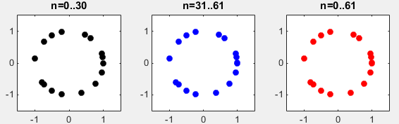
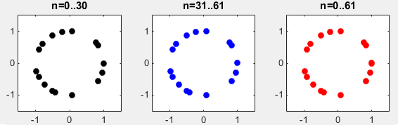
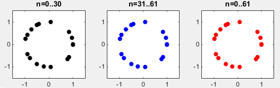
The signal generation algorithm of Pretrial PSS is same as LTE PSS. It generate three different Zadoff Chu sequences that are made up of 62 data points as shown below. This is same as LTE PSS signal generation.
Disclaimer : This code is just to push myself (probably readers) to look into the algorithm (formula) specified in the specification to the most detailed level. If you try to convert the specification into the programming code whatever language you choose, you will understand the equation / algorithm in much more detailed level than just reading the document. However, this code has not been verified with any real data.
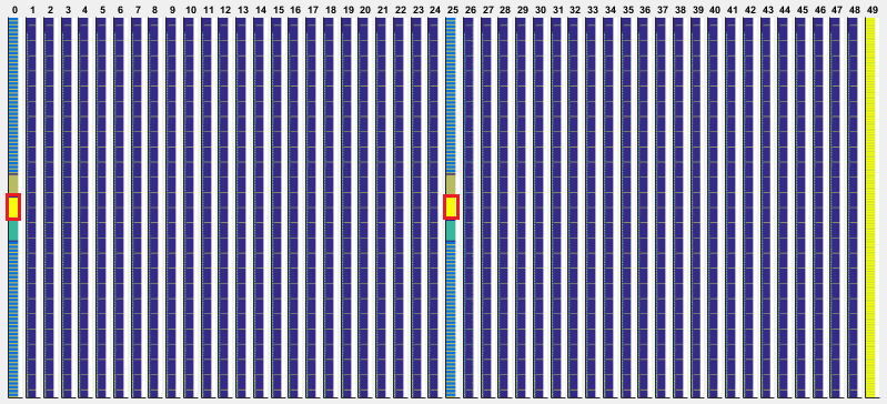
RE Mapping(Resource Element Mapping) of PSS
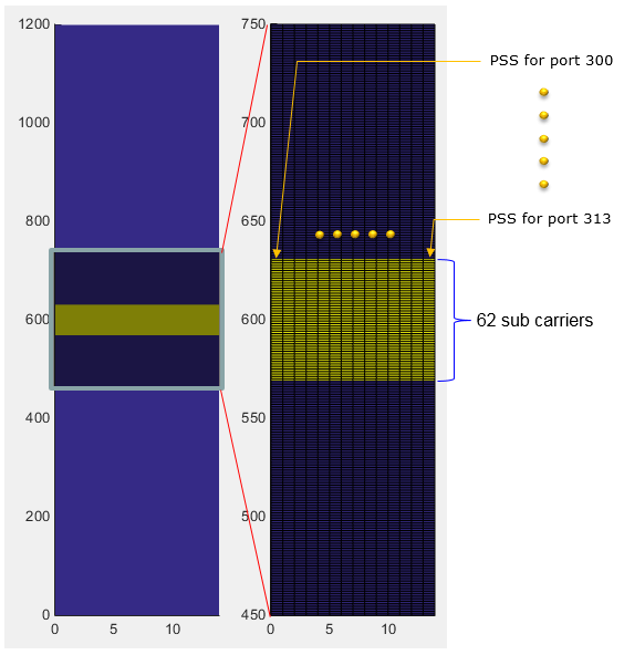
The location of PSS within a radio frame is as highlighed in red box below. It is at the center of the frequency domain in subframe 0 and 25.
If you cut out only subframe 0 and maginify the resource elements around the center frequency, it looks as shown below. In frequency domain allocation, it is same as in LTE PSS, but in time domain allocation you would find a big difference from LTE PSS. In case of LTE PSS, it occupies only one OFDM symbol but in 5G Pretrial it occupies the whole subframe (i.e, 14 OFDMA Symbols). Why it use 14 OFDMA symbols ? Actually, the data being carried by each OFDM symbol is same in every symbol. The difference is with antenna ports. As you see below, each of OFDM symbol for PSS is mapped to different antenna ports. These antenna ports will use different Beam Configuration. In short, the same PSS signal is being transmitted in every symbols in subframe 0 and 25 with different beam direction for each symbol. (If you are interested in the fundamental idea of this type of transmission, refer to Synchronization Signal in a frame structure).
Matlab Code : PSS
|
|||||||||||||||