The 5G Positioning Reference Signal (PRS) is a specialized feature introduced in 5G networks to enable advanced positioning services, offering high-accuracy location information with centimeter-level precision, a significant improvement over previous generations like 3G and 4G. This capability is essential for a variety of cutting-edge applications, including vehicle navigation for autonomous and connected cars, drone control for delivery and surveillance, and the management of robots in factories, where precise positioning is critical for safe and efficient operation. By leveraging 5G’s wide bandwidth, low latency, and advanced technologies like massive MIMO and beamforming, PRS supports real-time, reliable location tracking both indoors and outdoors, driving innovation in smart cities, industrial automation etc
Why PRS ? How to Deploy ?
-
Higher Density PRS Transmission: More frequent PRS symbols in time domain improve accuracy.
-
Adaptive PRS Configuration: PRS can be transmitted selectively based on UE mobility and positioning requirements.
-
Multi-beam PRS Transmission: Beam-based PRS improves location accuracy, especially in millimeter-wave (mmWave) bands.
-
Inter-frequency PRS: PRS is transmitted across different frequency bands to maximize positioning coverage and signal reliability.
Compared to LTE, 5G PRS provides wider bandwidths (e.g., 100 MHz in FR1 and 400 MHz in FR2), leading to finer resolution in ToA estimation. Moreover, the paper explains how hybrid approaches, such as PRS-assisted GNSS and sensor fusion, enhance reliability under challenging conditions like urban environments.
-
Time Difference of Arrival (TDoA): Measures the time delay between PRS receptions from multiple base stations (gNBs) to determine position.
-
Uplink Time Difference of Arrival (UL-TDoA): UE transmits reference signals (e.g, SRS), and the network calculates positioning based on reception times.
-
Angle of Arrival (AoA): Determines the UE's location by analyzing the direction of received PRS signals at multiple gNB antennas.
-
Hybrid Positioning: Combines PRS with RTK-GNSS, IMU sensors, and AI-based signal fusion for highly accurate tracking.
In addition PRS transmission schemes can be optimized to reduce energy consumption for low-power positioning for battery-constrained devices such as IoT sensors and wearables.
Why separate reference signal like PRS in stead of using SSB ?
While both Positioning Reference Signals (PRS) and Synchronization Signal Blocks (SSB) are used in 5G networks, they serve different purposes, and PRS is specifically designed for high-precision positioning, which SSB isn’t optimized for. SSB is too constrained for positioning because of its fixed transmission structure, limited bandwidth, and lack of timing configurability. PRS and SRS, on the other hand, are highly configurable, bandwidth-efficient, and optimized for time-based localization techniques.
Following is a comparative tables between SSB and Positioning Oriented Reference signal.
|
Feature |
SSB |
PRS |
SRS |
|---|---|---|---|
|
Primary Purpose |
Synchronization & Beam Sweeping |
Downlink Positioning (DL-TDoA, AoA) |
Uplink Positioning (UL-TDoA, AoA) |
|
Timing Accuracy |
Limited (Fixed Transmission) |
High (Configurable Timing) |
High (Dynamic Scheduling) |
|
Physical Resource Allocation Flexibility |
Limited (Cell ID-based staggering but fixed transmission locations) |
High (Fully configurable in time and frequency to minimize interference) |
High (Dynamic scheduling for UL-TDoA positioning with frequency multiplexing) |
|
Bandwidth |
Narrow (Limited to 20 RBs) |
Wide (Supports Large Bandwidths) |
Wide (Up to 100 MHz in FR1, 400 MHz in FR2) |
|
Configurable Periodicity |
Limited |
Yes |
Yes |
|
Beamforming Support |
Limited |
Yes |
Yes |
|
Multipath Robustness |
Low |
High (Multi-layer PRS) |
High (Adaptive SRS) |
Followings are further breakdown and descriptions of each aspect
Timing Accuracy & Precision - SSB Timing Constraints:
- SSB is primarily designed for cell search and synchronization, not for precise time-based positioning measurements.
- The symbol timing of SSB is not flexible, and it is transmitted in predefined locations in time and frequency.
- The periodicity of SSB (e.g., 20ms or longer) limits the granularity of time-based measurements, making it unsuitable for high-accuracy positioning.
- PRS/SRS Advantage:
- PRS and SRS support finer time-domain granularity, allowing precise Time of Arrival (ToA) and Time Difference of Arrival (TDoA) calculations.
- PRS can be beamformed for improved positioning in dense and urban environments.
- SRS allows high-precision UL-TDoA measurements due to its flexible transmission pattern.
Bandwidth & Resolution for ToA/TDoA - SSB Limitation:
- SSB is transmitted over a limited bandwidth (typically 20 RBs in FR1, 24 RBs in FR2), reducing the resolution of ToA measurements.
- Narrow bandwidth results in higher timing uncertainty, leading to larger positioning errors.
- PRS/SRS Advantage:
- PRS and SRS utilize wider bandwidths, which improves the time resolution of positioning measurements.
- Wider bandwidth provides finer time-domain resolution, reducing the ranging error in TDoA calculations.
Physical Resource Allocation Flexibility for Interference Mitigation - SSB Limitation:
- Limited flexibility in resource allocation—SSB placement is determined by cell ID-based staggering, meaning different cells can have offset SSB transmissions to reduce overlap.
- However, SSB transmission locations are still predefined and cannot be fully optimized for positioning needs.
- No fine-grained control over transmission periodicity or bandwidth allocation, making it harder to adapt to varying network conditions.
- In dense deployments, SSB signals from neighboring cells can still cause interference, especially in positioning scenarios where precise timing and frequency control are required.
- PRS/SRS Advantage:
- Fully configurable resource allocation, allowing operators to optimize PRS placement in both time and frequency.
- Time-domain flexibility: PRS transmission can be scheduled dynamically, with different cells using non-overlapping time slots to minimize inter-cell interference.
- Frequency-domain flexibility: PRS can be spread across different frequency resources, enabling frequency multiplexing to further reduce interference.
- Adaptive transmission density: PRS periodicity can be adjusted based on environmental factors, such as high-density urban areas vs. sparse rural deployments.
- Improved positioning accuracy due to lower inter-cell interference and better signal quality for time-of-arrival (ToA) and angle-of-arrival (AoA) measurements.
Flexibility & Configurability - SSB Limitation:
- SSB has fixed transmission configurations, which means:
- It cannot be dynamically scheduled based on UE positioning needs.
- It does not support multiple configurations for different positioning scenarios (e.g., urban vs. rural).
- PRS/SRS Advantage:
- PRS and SRS allow network-controlled transmission timing, periodicity, and beamforming, improving accuracy in various environments.
- SRS in UL-TDoA positioning is fully configurable, meaning:
- It can be scheduled at higher rates for low-latency positioning.
- It can use wider bandwidths in mmWave for finer resolution.
Multipath & Beamforming Considerations - SSB Limitation:
- SSB is not optimized for positioning in multipath environments (e.g., urban canyons, indoors).
- SSB does not leverage beamforming for positioning, which limits its accuracy in non-line-of-sight (NLoS) conditions.
- PRS/SRS Advantage:
- PRS and SRS support beamformed transmission, which improves signal quality for positioning in multipath-heavy environments.
- PRS supports multi-layer transmission, enhancing positioning accuracy through multi-path diversity.
Dedicated Positioning Capabilities in 3GPP - SSB Limitation:
- SSB is primarily used for cell detection, synchronization, and beam sweeping, and not optimized for positioning.
- It lacks specific enhancements for positioning such as:
- Higher density transmission
- Inter-frequency measurement support
- Optimized scheduling for location computation
- PRS/SRS Advantage:
- PRS and SRS are specifically designed for positioning, meeting the 3GPP Release 16+ positioning requirements for:
- E911 emergency services
- V2X (Vehicle-to-Everything)
- Industrial and URLLC applications
- They are integrated with network-based positioning functions like LMF (Location Management Function) in 5GC.
Physical Resources for PRS ?
Following illustration shows how PRS signal is generated and allocated to 5G/NR physical resource grid. It describes on the initialization sequence c_init using the PRS scrambling identity, the slot number, and other parameters.
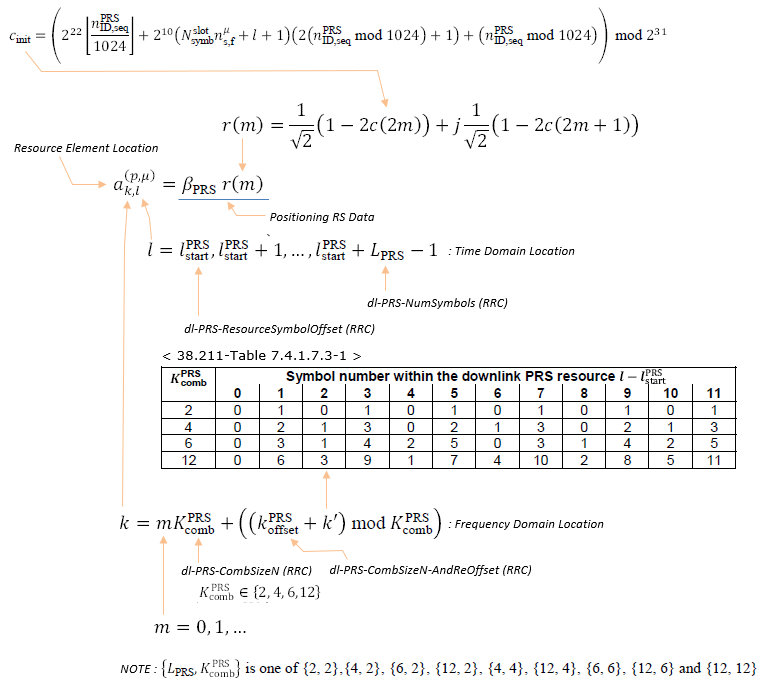
Figure 1. The comb pattern is not a fixed grid. Table 7.4.1.7.3-1 shifts the occupied subcarrier on every symbol, so a PRS resource sweeps the whole comb rather than sitting on one tone.
- The sequence r(m) represents the resource elements for PRS.
- Time domain and frequency domain locations for these elements are defined by specific indices and parameters, such as lPRSstart and KPRScomb
- The table (38.211-Table 7.4.1.7.3-1) provides symbol number mapping within the downlink resource grid. In short, it gives k' value based on KPRScomb and (l - lPRSstart)
- The formula k = m * KPRScomb + ((kPRSoffset + k') mod KPRScomb indicates the frequency domain location of PRS.
- The two comb parameters in the picture are not alternatives. 38.211 clause 7.4.1.7.3 takes the comb size from dl-PRS-CombSizeN-AndReOffset for a resource configured for RTT based propagation delay compensation, and from dl-PRS-CombSizeN otherwise.
- LPRS and KPRScomb cannot be chosen independently. Only certain pairs are allowed, and the note at the bottom of the picture lists them.
That pair list has grown since the picture was drawn. The note gives nine combinations of LPRS and KPRScomb, which are {2,2}, {4,2}, {6,2}, {12,2}, {4,4}, {12,4}, {6,6}, {12,6} and {12,12}. 38.211 v19.4.0 clause 7.4.1.7.3 now lists thirteen, adding {1,2}, {1,4}, {1,6} and {1,12}.
The four new entries all share one value. LPRS of 1 means a PRS resource that occupies a single OFDM symbol, which Release 18 introduced. The same addition appears in the RRC Parameters section, where dl-PRS-NumSymbols gained an n1 value in place of one of its spare codepoints.
Comb size and duration are linked : only thirteen pairs of LPRS and KPRScomb are allowed, and a wider comb needs more symbols to cover it.A full sweep needs LPRS at least equal to KPRScomb : with comb 6 and six symbols, every subcarrier of the comb is used exactly once.Release 18 added the single symbol case : LPRS of 1 is allowed with every comb size, and that resource covers only one offset of the comb.Two RRC parameters give the comb size : dl-PRS-CombSizeN normally, and dl-PRS-CombSizeN-AndReOffset for RTT based propagation delay compensation.The row of the table is the comb size : KPRScomb selects the row, and the symbol offset within the resource selects the column.
Example
What the picture is really showing is Table 7.4.1.7.3-1 applied. Each TRP walks the same comb pattern, and the three of them start from different offsets. Six symbols and comb 6 mean every subcarrier of one PRB carries exactly one TRP, with nothing left over and nothing colliding.
This example illustrates a case of Comb-6 Downlink Positioning Reference Signal (DL-PRS) allocation across multiple Transmission Reception Points (TRPs) in time-frequency resources.
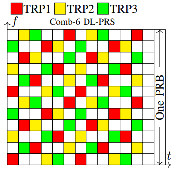
Image Source : Positioning in 5G networks
Figure 2. Three TRPs fit inside one PRB without overlapping. That is what a comb offset buys, and it is why a UE can separate them.
Followings are some highlights to note
- The term Comb-6 indicates that the PRS signals are transmitted every 6th subcarrier in the frequency domain, which helps in reducing interference and improving positioning accuracy.
- This structure allows multiple TRPs to transmit PRS in an interleaved manner, ensuring better spatial diversity and positioning resolution.
- Each TRP transmits PRS in a distinct, staggered pattern(Red (TRP1), Yellow (TRP2), and Green (TRP3)) to ensure that PRS signals do not interfere with each other.
- This improves the separation of received signals at the UE, which is crucial for Time Difference of Arrival (TDoA) and Angle of Arrival (AoA) positioning methods
Followings how the physical resource elements are allocated for TRP 1 in this example.
Step 1: Recall the Frequency Domain Location Formula
k = mKPRScomb + ((kPRSoffset + k') mod KPRScomb)
- KPRScomb = 6 (from the highlighted row).
- k' values from the table: 0, 3, 1, 4, 2, 5, 0, 3, 1, 4, 2, 5
- kPRSoffset is assumed to be 0 for simplicity.
- m takes values 0 and 1, meaning PRS will be allocated in two separate frequency locations.
Step 2: Compute k values for m = 0 and m = 1
For m = 0:
k = (0)(6) + (k' mod 6) = k'
PRS subcarrier indices: 0, 3, 1, 4, 2, 5, 0, 3, 1, 4, 2, 5
For m = 1:
k = (1)(6) + (k' mod 6) = 6 + k'
PRS subcarrier indices: 6, 9, 7, 10, 8, 11, 6, 9, 7, 10, 8, 11
Step 3: Final PRS Subcarrier Allocation for TRP1
- m = 0: PRS Subcarriers → 0, 3, 1, 4, 2, 5, 0, 3, 1, 4, 2, 5
- m = 1: PRS Subcarriers → 6, 9, 7, 10, 8, 11, 6, 9, 7, 10, 8, 11
Step 4: Interpretation
- The first PRS set (m=0) is allocated in subcarriers 0-5.
- The second PRS set (m=1) is allocated in subcarriers 6-11.
- This ensures PRS tones are evenly distributed across the 12 subcarriers in a PRB.
- Different TRPs (e.g., TRP2, TRP3) follow a different offset, ensuring proper separation for positioning.
How PRS is utilized ?
PRS in 5G is a dedicated downlink signal designed to enhance the accuracy of device localization at the physical layer. It enables high-precision positioning by leveraging time-based and angle-based measurements such as Time Difference of Arrival (TDoA) and Angle of Arrival (AoA). PRS is transmitted in a structured pattern across multiple frequency and time resources, allowing the UE to measure arrival times from different Transmission Reception Points (TRPs). These measurements are then processed to estimate the device's location with sub-meter accuracy. The flexible allocation of PRS in the time-frequency grid helps minimize interference and improve robustness in multipath environments. With the integration of advanced beamforming techniques and wider bandwidths, PRS enhances positioning performance, making it a critical component in applications like emergency response, autonomous vehicles, and industrial automation.
Following figure illustrate a possible use case of PRS for high resolution positioning. It depicts a scenario where a UE (e.g, a smartphone) determines its location using PRS signals transmitted from multiple TRPs(e.g, gNB). The PRS signals, labeled as "DL-PRS Resources," are downlink signals sent from the TRPs, shown as red and green lobes extending toward the UE, enabling measurements of distance and angles for accurate positioning.
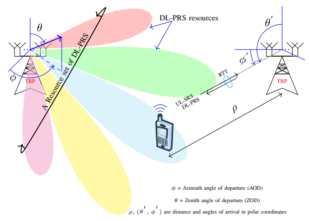
Image Source : Positioning in 5G networks
Figure 3. Downlink and uplink both carry positioning signals here. DL-PRS gives the UE the angles of departure, and the UL-SRS returning to the TRP completes the round trip measurement.
This is a breakdown and descriptions
Multi-TRP Positioning Using PRS
This use case illustrates a multi-TRP (Transmission Reception Point) positioning setup, where multiple TRPs transmit Downlink PRS (DL-PRS) and receive Uplink SRS (UL-SRS) from the UE to determine its location. The UE listens to PRS signals and performs positioning measurements such as Time of Flight (ToF), Time Difference of Arrival (TDoA), and Angle of Arrival (AoA).
Key Positioning Parameters
- DL-PRS Resources:
The PRS signals are transmitted from multiple TRPs in beamformed directions (colored lobes). These beams help determine the Azimuth Angle of Departure (AOD) φ and Zenith Angle of Departure (ZOD) θ. The UE measures arrival time and phase differences to estimate its distance from the TRPs.
- UL-SRS for Round Trip Time (RTT):
The UE sends an Uplink Sounding Reference Signal (UL-SRS) back to the TRP. The TRP then computes Round Trip Time (RTT), which provides an additional time-based measure for positioning.
- Position Estimation in Polar Coordinates:
The UE location is determined based on polar coordinates (ρ, θ', φ'), where:
- ρ represents the distance of the UE from the TRPs.
- θ' and φ' are the angles of arrival (AoA) at the TRP, helping refine position accuracy.
Use Case and Benefits
This multi-TRP PRS-based positioning is particularly useful for:
- Urban positioning where GPS signals are blocked.
- V2X (Vehicle-to-Everything) communication to track vehicles in real-time.
- Factory automation and robotics, where sub-meter accuracy is required for autonomous navigation.
- Emergency location services (E911) where precise UE location is critical.
Two directions carry positioning signals : the UE measures DL-PRS, the TRP measures UL-SRS, and a round trip measurement needs both.The angles are measured at the transmitter : the beams give an azimuth and a zenith angle of departure, which is why a resource set rather than one resource is configured.One TRP pair fixes a curve, not a point : a single time difference leaves the UE somewhere on a hyperbola, and further pairs narrow the intersection.Round trip time avoids the synchronization problem : a time difference method needs the TRPs aligned in time, and a round trip measurement cancels the offset instead.The UE reports, the network computes : the measurements are collected by the LMF, so nothing on this page produces a position on its own.
RRC Parameters
The definitions below fall into two groups, and the split follows the direction of the signal. The first group configures the downlink PRS the UE measures. The second configures the uplink SRS the UE transmits for the network to measure, which is the other half of every round trip method described above.
Following is based on
NR-DL-PRS-PDC-Info-r17 ::=    SEQUENCE {
    nr-DL-PRS-PDC-ResourceSet-r17          NR-DL-PRS-PDC-ResourceSet-r17                    OPTIONAL, -- Need R
    ...
}

NR-DL-PRS-PDC-ResourceSet-r17 ::=    SEQUENCE {
    periodicityAndOffset-r17     NR-DL-PRS-Periodicity-and-ResourceSetSlotOffset-r17,
    numSymbols-r17               ENUMERATED {n2, n4, n6, n12, n1-v1800, spare3, spare2, spare1},
    dl-PRS-ResourceBandwidth-r17        INTEGER (1..63),
    dl-PRS-StartPRB-r17                 INTEGER (0..2176),
    resourceList-r17             SEQUENCE (SIZE (1..maxNrofPRS-ResourcesPerSet-r17)) OF NR-DL-PRS-Resource-r17,
    repFactorAndTimeGap-r17      RepFactorAndTimeGap-r17                                    OPTIONAL,   -- Need S
    ...
}

NR-DL-PRS-Periodicity-and-ResourceSetSlotOffset-r17 ::= CHOICE {
    scs15-r17       CHOICE {
                        n4-r17                  INTEGER (0..3),
                        n5-r17                  INTEGER (0..4),
                        n8-r17                  INTEGER (0..7),
                        n10-r17                 INTEGER (0..9),
                        n16-r17                 INTEGER (0..15),
                        n20-r17                 INTEGER (0..19),
                        n32-r17                 INTEGER (0..31),
                        n40-r17                 INTEGER (0..39),
                        n64-r17                 INTEGER (0..63),
                        n80-r17                 INTEGER (0..79),
                        n160-r17                INTEGER (0..159),
                        n320-r17                INTEGER (0..319),
                        n640-r17                INTEGER (0..639),
                        n1280-r17               INTEGER (0..1279),
                        n2560-r17               INTEGER (0..2559),
                        n5120-r17               INTEGER (0..5119),
                        n10240-r17              INTEGER (0..10239),
                        ...
    },
    ...                                                                 -- the scs30-r17, scs60-r17 and scs120-r17 branches follow the same shape
}

NR-DL-PRS-Resource-r17 ::= SEQUENCE {
    nr-DL-PRS-ResourceID-r17            NR-DL-PRS-ResourceID-r17,
    dl-PRS-SequenceID-r17               INTEGER (0..4095),
    dl-PRS-CombSizeN-AndReOffset-r17    CHOICE {
            n2-r17                          INTEGER (0..1),
            n4-r17                          INTEGER (0..3),
            n6-r17                          INTEGER (0..5),
            n12-r17                         INTEGER (0..11),
            ...
    },
    dl-PRS-ResourceSlotOffset-r17       INTEGER (0..maxNrofPRS-ResourceOffsetValue-1-r17),
    dl-PRS-ResourceSymbolOffset-r17     INTEGER (0..12),
    dl-PRS-QCL-Info-r17                 DL-PRS-QCL-Info-r17                         OPTIONAL, -- Need N
    ...,
    [[
    dl-PRS-ResourceSymbolOffset-v1800   INTEGER (13)                                OPTIONAL  -- Need R
    ]]
}

DL-PRS-QCL-Info-r17 ::= CHOICE {
    ssb-r17                     SEQUENCE {
        ssb-Index-r17                   INTEGER (0..63),
        rs-Type-r17                     ENUMERATED {typeC, typeD, typeC-plus-typeD},
        ...
    },
    dl-PRS-r17                  SEQUENCE {
        qcl-DL-PRS-ResourceID-r17       NR-DL-PRS-ResourceID-r17,
        ...
    },
    ...
}

NR-DL-PRS-ResourceID-r17 ::= INTEGER (0..maxNrofPRS-ResourcesPerSet-1-r17)

RepFactorAndTimeGap-r17 ::=  SEQUENCE {
    repetitionFactor-r17         ENUMERATED {n2, n4, n6, n8, n16, n32, spare2, spare1},
    timeGap-r17                  ENUMERATED {s1, s2, s4, s8, s16, s32, spare2, spare1}
}
Two Release 18 additions are visible in that group, and both point at the same feature. The field numSymbols-r17 now offers
The second is an extension group on NR-DL-PRS-Resource-r17. The base field dl-PRS-ResourceSymbolOffset-r17 stops at 12, and
The resource set holds the timing and the resources hold the pattern : periodicity, bandwidth and start PRB are set once per set, and comb size and offsets are set per resource.The periodicity choice is indexed by subcarrier spacing first : scs15, scs30, scs60 and scs120 each carry their own list of periods, and the offset range always stops one below the period.A PRS resource can be quasi co-located with an SSB or with another PRS : DL-PRS-QCL-Info-r17 is a two way choice, and the SSB branch names typeC, typeD or both.Repetition and time gap travel together : RepFactorAndTimeGap-r17 pairs a repetition factor with the slot gap between repetitions.Release 18 shortened the minimum resource : n1-v1800 and the symbol offset of 13 together allow a single symbol PRS anywhere in the slot.
The second group is the uplink side. SRS-Config is the ordinary sounding reference signal configuration, and the positioning work sits in the fields carrying a Pos in their name. Release 16 added those inside an extension group rather than as new top level members.
Following is based on
SRS-Config ::=                          SEQUENCE {
    srs-ResourceSetToReleaseList            SEQUENCE (SIZE(1..maxNrofSRS-ResourceSets)) OF SRS-ResourceSetId        OPTIONAL, -- Need N
    srs-ResourceSetToAddModList             SEQUENCE (SIZE(1..maxNrofSRS-ResourceSets)) OF SRS-ResourceSet          OPTIONAL, -- Need N
    srs-ResourceToReleaseList               SEQUENCE (SIZE(1..maxNrofSRS-Resources)) OF SRS-ResourceId              OPTIONAL, -- Need N
    srs-ResourceToAddModList                SEQUENCE (SIZE(1..maxNrofSRS-Resources)) OF SRS-Resource                OPTIONAL, -- Need N
    tpc-Accumulation                        ENUMERATED {disabled}                                                   OPTIONAL, -- Need S
    ...,
    [[
    srs-RequestDCI-1-2-r16                  INTEGER (1..2)                                                          OPTIONAL, -- Need S
    srs-RequestDCI-0-2-r16                  INTEGER (1..2)                                                          OPTIONAL, -- Need S
    srs-ResourceSetToAddModListDCI-0-2-r16  SEQUENCE (SIZE(1..maxNrofSRS-ResourceSets)) OF SRS-ResourceSet          OPTIONAL, -- Need N
    srs-ResourceSetToReleaseListDCI-0-2-r16 SEQUENCE (SIZE(1..maxNrofSRS-ResourceSets)) OF SRS-ResourceSetId        OPTIONAL, -- Need N
    srs-PosResourceSetToReleaseList-r16     SEQUENCE (SIZE(1..maxNrofSRS-PosResourceSets-r16)) OF SRS-PosResourceSetId-r16
                                                                                                                    OPTIONAL, -- Need N
    srs-PosResourceSetToAddModList-r16      SEQUENCE (SIZE(1..maxNrofSRS-PosResourceSets-r16)) OF SRS-PosResourceSet-r16        OPTIONAL,-- Need N
    srs-PosResourceToReleaseList-r16        SEQUENCE (SIZE(1..maxNrofSRS-PosResources-r16)) OF SRS-PosResourceId-r16            OPTIONAL,-- Need N
    srs-PosResourceToAddModList-r16         SEQUENCE (SIZE(1..maxNrofSRS-PosResources-r16)) OF SRS-PosResource-r16  OPTIONAL  -- Need N
    ]],
    [[
    dci-TriggeringPosResourceSetLink-r18    ENUMERATED { enabled }                                                  OPTIONAL  -- Need R
    ]],
    [[
    srs-TwoSeparatePowerControlAdjustmentStates-r19   ENUMERATED {enabled}                                          OPTIONAL, -- Need R
    tpc-OfSRS-ClosedLoopIndexInDCI-1-1-r19            ENUMERATED {enabled}                                          OPTIONAL, -- Need R
    srs-ClosedLoopIndexIndicatorInDCI-1-1-r19         ENUMERATED {enabled}                                          OPTIONAL  -- Need R
    ]]
}

SRS-PosResourceSet-r16 ::=                  SEQUENCE {
    srs-PosResourceSetId-r16                    SRS-PosResourceSetId-r16,
    srs-PosResourceIdList-r16                   SEQUENCE (SIZE(1..maxNrofSRS-ResourcesPerSet)) OF SRS-PosResourceId-r16
                                                                                                           OPTIONAL, -- Cond Setup
    resourceType-r16                            CHOICE {
        aperiodic-r16                               SEQUENCE {
            aperiodicSRS-ResourceTriggerList-r16        SEQUENCE (SIZE(1..maxNrofSRS-TriggerStates-1))
                                                            OF INTEGER (1..maxNrofSRS-TriggerStates-1)     OPTIONAL, -- Need M
            ...
        },
        semi-persistent-r16                         SEQUENCE {
            ...
        },
        periodic-r16                                SEQUENCE {
            ...
        }
    },
    alpha-r16                                   Alpha                                                      OPTIONAL, -- Need S
    p0-r16                                      INTEGER (-202..24)                                         OPTIONAL, -- Cond Setup
    pathlossReferenceRS-Pos-r16                 CHOICE {
        ssb-IndexServing-r16                        SSB-Index,
        ssb-Ncell-r16                               SSB-InfoNcell-r16,
        dl-PRS-r16                                  DL-PRS-Info-r16
    }                                                                                                      OPTIONAL, -- Need M
    ...
}

DL-PRS-Info-r16  ::=                SEQUENCE {
    dl-PRS-ID-r16                      INTEGER (0..255),
    dl-PRS-ResourceSetId-r16           INTEGER (0..7),
    dl-PRS-ResourceId-r16              INTEGER (0..63)                                                     OPTIONAL  -- Need S
}
SRS-Config has gained two extension groups since the version this page carried. Release 18 added dci-TriggeringPosResourceSetLink-r18, and Release 19 added three fields covering a second power control adjustment state and the closed loop index in DCI format 1_1. None of them changes how a positioning SRS resource is described.
The last definition is the one that connects back to the first group. DL-PRS-Info-r16 names a downlink PRS resource by its PRS identity, resource set and resource, and SRS-PosResourceSet-r16 uses it as a pathloss reference. The UE therefore sets its uplink positioning power from a downlink PRS rather than from an SSB, when the network asks it to.
Positioning SRS is a separate resource family : the Pos fields sit alongside the ordinary SRS lists rather than replacing them.All three timing types are offered : a positioning SRS resource set can be aperiodic, semi-persistent or periodic.The pathloss reference can be a PRS : pathlossReferenceRS-Pos-r16 chooses between a serving SSB, a neighbour SSB and a downlink PRS.DL-PRS-Info-r16 is a three level address : PRS identity, resource set identity, and optionally one resource inside that set.The two groups meet here : the downlink definitions above configure what the UE measures, and this field is where an uplink transmission is tied back to one of them.
Reference :
- The 5G Evolution:3GPP Releases 16-17 (5G Americas)
- TR 38.855 - Study on NR positioning support
- 5G positioning: What you need to know - Ericsson (2020)
- Positioning in 5G networks - arXiv (2021)
- 38.211 v19.4.0 : NR - Physical channels and modulation. Clause 7.4.1.7 defines the positioning reference signals, and Table 7.4.1.7.3-1 gives the comb pattern quoted above.
- 38.331 v19.3.0 : NR - Radio Resource Control (RRC) protocol specification. Every definition in the RRC Parameters section is quoted from it.
YouTube
- 5G Positioning Tutorial
- 5G Precise Indoor Positioning (Qualcomm)
- How will 5G impact the positioning industry?
- Radio Based Positioning in 5G Networks and Beyond
- Addressing the challenges of the new 5G Release 16 Location Based Services Requirements