A Rel-17 power-saving deep-dive — starting from how paging works today, why that costs power, and then the RRC parameters and the over-the-air packet that fix it. Diagrams shown are drafts; I will refine them in the full document.
- Paging today — flow, message, wake-up cost — and why PEI appeared
- How PEI is transmitted — the OTA packet & RRC parameters
- Aggregation level — why it decides if PEI is decoded
- SSB close vs far from PEI (why SSB-first)
- Subgrouping — what PEI means per subgroup
- PDCCH skipping (the connected-mode sibling)
- Intuitive understanding — UE side & when we can skip
- Power optimization — a worked example
- References
1 Paging today — flow, message, wake-up cost — and why PEI appeared
Paging is designed to reach a UE while allowing it to remain in a low-power idle or inactive state. Instead of continuously monitoring the downlink, the UE wakes up only at periodically calculated Paging Occasions and checks whether the network has scheduled a paging message for it. This mechanism already saves a significant amount of power, but it still requires the UE to wake up, restore synchronization, monitor the paging PDCCH, and sometimes decode the paging PDSCH even when no paging message is intended for that UE.
For many devices, especially wearables, sensors, and other IoT devices, most Paging Occasions do not contain relevant paging. As a result, the UE repeatedly spends energy only to confirm that there is nothing to receive. The cost of each individual check may be small, but the repeated receiver activation, synchronization, control-channel decoding, and sleep-state transitions can become a meaningful part of the total power consumption.
Paging Early Indication, or PEI, was introduced to reduce this unnecessary wake-up cost. PEI provides an earlier and simpler indication of whether the UE needs to monitor the upcoming Paging Occasion. When PEI indicates that paging is not expected, the UE can skip the paging PDCCH monitoring and return to, or remain in, a deeper sleep state. In this way, PEI does not change the basic purpose of paging. It adds an early decision point that helps the UE avoid performing the full paging reception procedure when it is not needed.
1.1 · How paging works today, before PEI
Every idle/inactive UE camps on a cell with a DRX (paging) cycle — typically the cell's defaultPagingCycle from SIB1, or a UE-specific/extended value (eDRX) if configured. From that cycle length T and its own ID, the UE computes exactly one Paging Frame (PF) and Paging Occasion (PO) per cycle — a specific SFN and subframe/slot where it, and only it (plus everyone sharing that PO), needs to check for paging.
At that PO, in every single DRX cycle — paged or not — the UE has to: wake its receiver, run sync (AGC/FTL/TTL) if it isn't already tracking the cell tightly, and blind-decode the PDCCH looking for a DCI scrambled with P-RNTI. This decode attempt happens whether or not anyone is actually paging that UE this cycle.
1.2 · What's inside the paging message
If a P-RNTI DCI is found, it schedules a PDSCH carrying the RRC Paging message. That message is a list of Paging Records — one per UE being paged in that PO — each record holding a UE identity (typically the 5G-S-TMSI, sometimes full I-RNTI for RRC_INACTIVE) and an access type indicator. The UE has to decode the whole record list and compare every entry against its own ID to find out whether it was the one being called.
1.3 · The wake-up cost — paid every cycle, whether paged or not
Before PEI, the UE had no early indication of whether an upcoming Paging Occasion was relevant to it. Therefore, at every paging cycle, it had to wake the receiver, restore synchronization, search the PDCCH for P-RNTI, and, when paging was scheduled, decode the Paging message and compare the paging records with its own identity.
However this processing was required even when the UE was not paged, which is the normal case for most idle UEs. In this case, the UE repeatedly pays the wake-up, synchronization, and control-channel decoding cost simply to confirm that no paging message was intended for it.
RECEIVER |
SYNC |
PDCCH |
PDSCH |
powers up from sleep, not free |
AGC / FTL / TTL re-acquisition |
blind-decode search for P-RNTI across candidates |
decode + compare paging record list |
None of this is optional under the pre-PEI design — the only way to know whether you're being paged is to go through the whole decode. For a UE that's rarely actually paged (which is most idle UEs, most of the time), that means paying the full wake-up cost over and over for a "no" almost every time.
WHY PEI CAME INTO THE PICTURE
Paging reception itself is under ~2.5% of total power. The waste is the wake-up around it — exactly the LOOP (AGC/FTL/TTL) and PDCCH decode described above, run every cycle just to learn "not for me." PEI removes that wasted decode on the negative cycles and lets the UE sleep deeper, longer.
"Don't wake up the whole way just to find out nobody called."
Biggest win for devices that are idle most of the time — wearables, IoT, phones in a pocket.
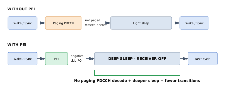
Fig 1 — Paging reception without PEI vs with PEI.
2 How PEI is transmitted — the OTA packet & the RRC parameters
Two layers to cover. The OTA packet — the DCI format 2_7 that carries the indication over the air, as a group-common DCI with its CRC scrambled by a dedicated RNTI (a compact payload, on the order of ~41 bits for licensed, ~43 for unlicensed) — and the RRC parameters the network broadcasts (in SIB1 / system information) that tell the UE where and how to look for it.
RRC PARAMETERS (THE CONFIGURATION)
RRC parameter (IE) |
What it means |
pei-SearchSpace |
Which search space carries the PEI. If SearchSpaceId = 0, the PEI MOs follow the RMSI (Type0-PDCCH) pattern; if > 0, a dedicated common search space is used. |
firstPDCCH-MonitoringOccasionOfPEI-O |
The starting PDCCH monitoring occasion of the PEI-O — the anchor the whole PEI-O is counted from. |
nrofPDCCH-MonitoringOccasionPerSSB-InPO |
The X factor — how many PDCCH monitoring occasions correspond to each SSB, so the PEI-O spans S×X occasions. |
po-NumPerPEI |
How many Paging Occasions a single PEI covers. |
payloadSizeDCI-2-7 |
The DCI 2_7 payload size — sets the total room for PO and subgroup indications. |
The PEI occasion (PEI-O) and the first PDCCH monitoring occasion
This is the most important structural point, so it's worth being precise. A PEI occasion is a set of S×X consecutive PDCCH monitoring occasions, where S is the number of actually-transmitted SSBs (from ssb-PositionsInBurst in SIB1) and X is nrofPDCCH-MonitoringOccasionPerSSB-InPO (or 1 if not configured). Each monitoring occasion in the PEI-O is tied to one SSB beam: the first PEI MO maps to the first transmitted SSB, the second to the second SSB, and so on. This is exactly why PEI naturally rides on the SSB — the beam the UE uses to read SSB #k is the same beam it uses to read PEI MO #k. Once a UE detects its PEI within the PEI-O, it is not required to monitor the remaining monitoring occasions of that same PEI-O — it stops early.
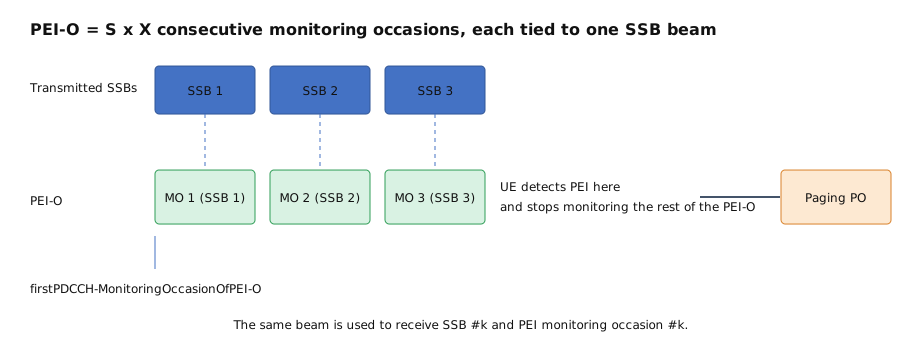
Fig 2 — PEI-O structure: S×X monitoring occasions, one per SSB beam, counted from the first MO.
3 Aggregation level — why it decides if PEI is decoded
Since PEI is a DCI on the PDCCH, whether a UE can actually read it comes down to aggregation level. This is a small but critical detail, and it chains all the way down to physical resources:
- DCI → PDCCH: the PEI (DCI 2_7) is carried on the PDCCH.
- PDCCH → CCE: the PDCCH is built from Control Channel Elements (CCEs). The aggregation level (AL) is how many CCEs carry that one DCI — 1, 2, 4, 8, or 16.
- CCE → REG: each CCE is made of 6 REGs (Resource Element Groups).
- REG → RE: each REG is one RB (12 Resource Elements) in one OFDM symbol, some of which carry DMRS.
The key idea: a higher aggregation level spreads the same DCI over more CCEs (more REs), which lowers the effective code rate and makes the DCI more robust — easier to decode in poor signal. A lower aggregation level is compact but fragile.
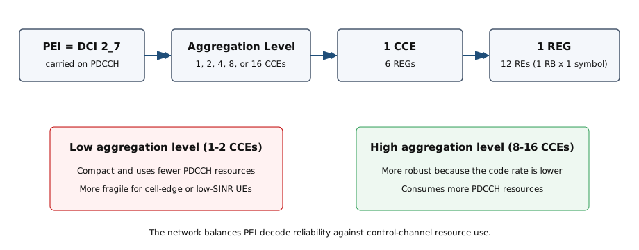
Fig 3 — Aggregation level chain: DCI → CCE → REG → RE, and the robustness trade-off.
Why this matters for PEI specifically: the PEI has to be decodable by the worst UE in the group, including cell-edge / low-SINR devices. If the network picks too low an aggregation level, those UEs fail to decode the PEI — and by the fallback rule they must then monitor the PO anyway, wiping out the saving for them. Pick too high, and PEI eats control-channel resource that could carry other DCIs. So aggregation-level selection is a real design and test lever — and it's the natural place to discuss what happens in good vs bad signal conditions.
On a personal note — I picked this topic up from 5G New Radio in Bullets by Chris Johnson, which I really like. It's excellent further reading for the PDCCH fundamentals (aggregation level, CCE, REG) underneath this.
4 SSB close vs far from PEI — why SSB-first?
The constraint. Sync (AGC/FTL/TTL) and measurements can only happen during SSB bursts, and decoding PEI needs the receiver already synced. So the distance between the SSB and the PEI decides the whole power budget.
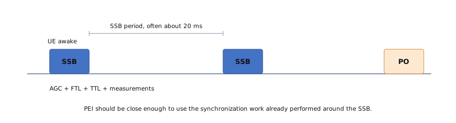
Fig 4 — Sync only "lives" near an SSB, so PEI must be reachable off that same wake-up.
Three placements
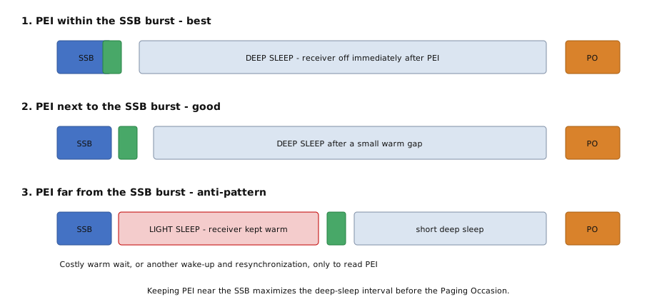
Fig 5 — PEI within SSB vs next to SSB vs far from SSB.
SSB far from PEI → the UE must keep the receiver warm in light sleep, or wake a second time and re-run sync just to read PEI — which can cost more than PEI ever saves.
WHY THIS MATTERS TO ME — THE VALIDATION ENGINEER'S JOB
This is exactly where most of my work lives.
As a validation engineer, the flow is: first understand the feature — we work closely with the developers to learn exactly how it behaves — then design the test scenarios that exercise it, and then decide which test equipment (TE) is the right one to reproduce those scenarios.
The cases that matter are almost always the corner conditions — and pinning those down is the essence of the job.
5 Subgrouping — what PEI means per subgroup
One PO is shared by many UEs. Subgrouping splits them so the PEI can wake only part of the group. The PEI carries a bitmap: one bit per subgroup. A UE only wakes if its bit is set.
- How the UE gets its subgroup: network-assigned (at registration) or UE-ID-derived.
- How subgroups are formed: by paging probability and power-consumption profile, so similar UEs share an indication — fewer false wake-ups.
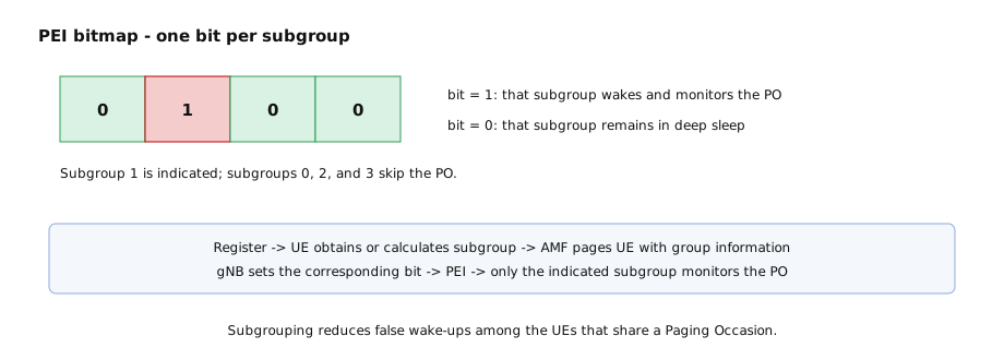
Fig 6 — Subgroup bitmap and message flow.
6 PDCCH skipping — the connected-mode sibling
Worth a short contrast because it completes the power-saving story. PEI saves power in idle/inactive by skipping the PO. PDCCH skipping saves power in connected mode: the network tells the UE it can stop monitoring PDCCH for a set span, so the UE doesn't decode control channels it doesn't need.
|
PEI |
PDCCH skipping |
State |
RRC_IDLE / RRC_INACTIVE |
RRC_CONNECTED |
What it skips |
the Paging Occasion |
PDCCH monitoring occasions |
Trigger |
early indication before PO |
explicit skip command |
Together they show the full idle ↔ connected saving picture.
7 Intuitive understanding — UE side & when we can skip
From the UE perspective, PEI adds a simple decision point before the normal Paging Occasion. The UE still wakes up near the SSB to restore synchronization and perform any required measurements, but instead of immediately monitoring the paging PDCCH, it first attempts to decode PEI. A negative PEI for the UE’s subgroup allows the UE to skip the Paging Occasion and return to deep sleep, while a positive PEI means that the UE continues with the normal paging procedure and checks whether the Paging message actually contains its identity.
This power saving is applied only when the UE can trust the PEI result. PEI must be properly configured and successfully decoded, the indication must be negative for the UE’s subgroup, and any measurements required during that cycle must already be completed. When PEI is missed, decoding is uncertain, or any required condition is not satisfied, the UE falls back to monitoring the normal Paging Occasion. Therefore, the practical benefit depends not only on how often the UE is paged, but also on PEI decoding reliability, subgroup paging activity, and how efficiently PEI reception can be combined with the UE’s existing SSB wake-up.
WHAT HAPPENS ON THE UE SIDE
- Wake near the SSB → do sync + measurements (needed anyway).
- Read the PEI on the back of that wake-up.
- PEI negative → main receiver OFF, deep sleep to next cycle.
- PEI positive → decode PO → read paging → connect only if it's really me.
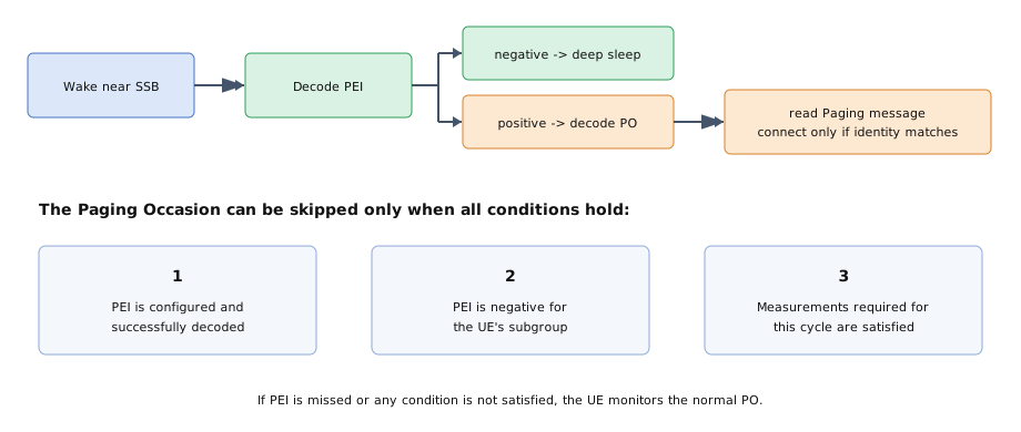
Fig 7 — UE-side flow and the conditions for skipping the PO.
IS IT REALLY HELPFUL?
The benefit is real but conditional. If a configured PEI isn't decoded, the UE must still monitor the PO (safety fallback). So the payoff lives or dies on three things: SSB proximity, decode reliability, and how often the group is actually paged.
8 Power optimization — a worked example
The clearest way to feel the impact is to scale it up. Imagine a cell with 100,000 idle devices camped on it, and in a given paging cycle only a small fraction are actually being paged — say 1%. Compare the two worlds:
- Without PEI: all 100,000 devices wake fully at their PO and decode the paging PDCCH — even though 99,000 of them were never paged. That's 100,000 full PO decodes this cycle.
- With PEI: all 100,000 read the cheap PEI on the back of the sync they were doing anyway. Only the ~1,000 whose subgroup is paged go on to decode the PO. The other ~99,000 turn the receiver off and deep-sleep.
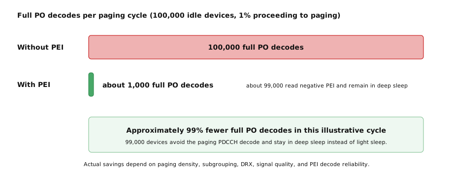
Fig 8 — Illustrative: 100,000 idle devices, ~1% paged per cycle, with vs without PEI.
Two things to notice. First, the saving compounds: this happens every paging cycle, on every device, all day — so a per-cycle 99% cut in wasteful decodes turns into a large aggregate battery and network gain. Second, the win depends on the same levers we discussed: good subgrouping keeps each device's effective paging rate low, and reliable PEI decoding (aggregation level, SSB proximity) ensures those 99,000 devices actually get to skip rather than falling back to the PO.
The 100,000 / 1% figures are illustrative to make the scaling intuitive — not a measured result. The real numbers depend on paging density, DRX cycle, and subgroup design.
9 References
[1] 3GPP TS 38.304 — UE procedures in idle mode and RRC inactive state (paging frame/occasion calculation, PEI, PEI-O, first PDCCH MO, S×X structure).
[2] 3GPP TS 38.331 — RRC (Paging message and PagingRecord IE; PEI-config IE: pei-SearchSpace, firstPDCCH-MonitoringOccasionOfPEI-O, nrofPDCCH-MonitoringOccasionPerSSB-InPO).
[3] 3GPP TS 38.213 — Physical layer procedures for control (DCI format 1_0 with P-RNTI, DCI format 2_7, monitoring occasions, aggregation levels, Type0-PDCCH).
[4] 3GPP TR 38.840 — Study on UE power saving in NR.
[5] Chris Johnson, 5G New Radio in Bullets — PDCCH fundamentals: aggregation level, CCE, and REG structure.
[6] MediaTek Inc., "Power efficient paging mechanism with paging early indicator," WO2021180206A1 (priority 12 Mar 2020). — core PEI-near-SSB concept, LOOP/MEAS framing, PEI-O placement.
[7] MediaTek Inc., "Downlink control information-based paging early indicator," US 12,477,515 (priority 8 Jul 2020). — DCI-based PEI (the DCI 2_7 route), PEI message formats.
[8] MediaTek Inc., "UE Grouping for Paging Enhancement," US 2022/0232514 A1 (priority 15 Jan 2021). — subgrouping bitmap, grouping by power-consumption profile and paging probability.
Abstract for pitch. Diagrams are drafts to be refined in the full document. Illustrative numbers are labelled as such. Verify all IE names / spec clauses against current 3GPP 38.304 / 38.331 / 38.213 before publishing.