NR PDCP is almost same as LTE PDCP. So if you are already faimiliar with LTE, you wouldn't need much of extra study to understand NR PDCP. If you are new to overall functionality of PDCP, I would suggest you to go through LTE PDCP page first. Since I wouldn't see any NR test equipment and UE in near future, I wouldn't be able to put much of practical information on NR PDCP until the equipment and UE are available. Your knowledge on LTE PDCP would help you understand NR PDCP.
Actually a large portions of the contents on this page comes from the direct copy of LTE PDCP page and I would try to highlight those parts which is unique to NR PDCP.
Overview / Overall Functionality
The data coming into the box (eNB or UE) first go through PDCP and then gets into RLC (Downlink Path). Data waiting in RLC trying to go out to the outside world has to go through PDCP to reach outside world(Uplink Path).
In the case when everything goes OK, you don't see any problems in protocol stack and just check protocol log you may think the function of PDCP looks simple and all it does is just to add/remove a small header to each packet and send/recieve it from/to RLC. But if you list up all the detailed functions of PDCP, you would get pretty long list as shown below. I would suggest you to go through this list over and over until you can write down this list from memory. Of course, you don't need to memorize these like you prepare the exam. Just read through this list as often as possible and try to elaborate each of these items in your own words.
- Transfer of data (user plane or control plane)
- Maintenance of PDCP SNs
- Header compression and decompression using the ROHC (Robust Header Compression)
- Ciphering and deciphering of user plane data and control plane data
- Integrity protection and integrity verification of control plane data
- Timer based SDU discard
- For split bearers, routing or duplication
- Reordering and in-order delivery
- Duplicate discarding
As in other layers, let's start looking into the diagram from 3GPP specification (TS 38.323). The first diagram is as follows.
What are we supposed to do ?
Yes, Verbalize it (describe it). i.e, explain the diagram in your own words.
In the following diagram, you see that PDCP is directly connected to RLC Layer (RLC UM and RLC AM).
Do you find anything strange or missing ?
Yes, PDCP has no connection to RLC TM mode, meaning RLC TM mode data does not go through PDCP.
< 38.323
-
Figure 4.2.1-1: PDCP layer, structure view > 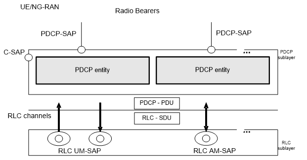
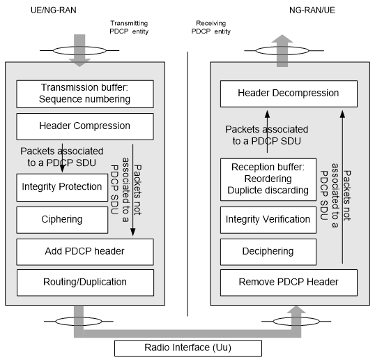
Following Diagram would give you more detailed information about PDCP Operation. Of course, all of the these functionality is listed in the 3GPP specification, but it would not become yours unless you combine these diagrams and the written descriptions in your own words.
Now let's follow through the diagram from left side.
- i) Data coming into PDCP first stored in a transmission buffer and go through "Sequence Numbering" Procedure. It means that PDCP add "Sequence Number" to each of incoming data block. Once it add 'Sequence Number', it has to manage the number. On reciever side, we can figure out many things like "Is the data getting delivered in order ? Is there any duplicate data ? How can I combine the multiple chunks of data block into an original big chunk data ?"
- ii) Then it goes through Header Compression. But it says "this applies only to U-plane data". It means that Signaling Message does not go through this Header Compression. Even though not shown in this diagram, we can disable Header Compression even for U-plane data (e.g, IP Packet data).
- iii) From here we see two paths, one through "Integrity/Ciphering" and the other one directly goes to the last step. Integrity Protection applies only to C-Plane data (C-Plane data means RRC/NAS message, i.e DCCH data, not DTCH data). Again you may disable "Integrity Protection" setp by applying a signaling message but we need to wait until RRC/NAS specification will come out for the details.
- iv) Then it goes to Ciphering process. Ciphering applies both C-Plane and U-Plane Data. Ciphering process can also may be disabled by applying a signaling message but we need to wait until RRC/NAS specification will come out for the details.
- v) Next, a PDCP header is added
- vi) If Split bearer is established, the PDCP routs the packet to the intended bearer.
The other side (right side, receiving side) is simply reverse process of transmission process. So I will leave this to the readers to interpret the diagram.
< 38.323 - Figure 4.2.2-1: PDCP layer, functional view >
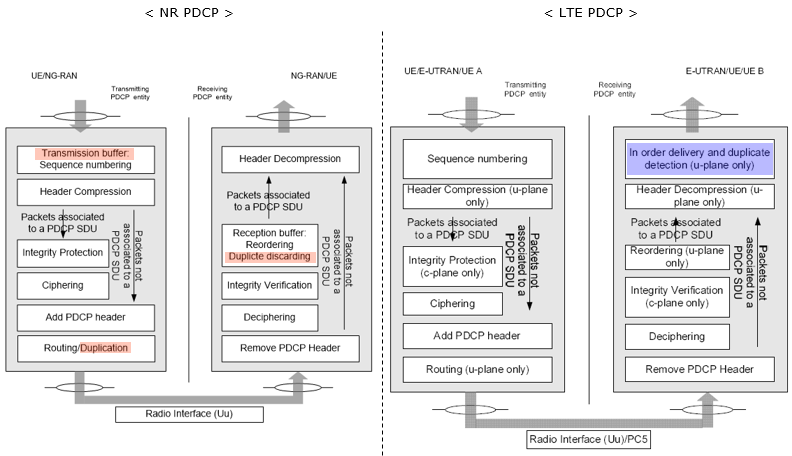
Even though the overal functionaliby of NR PDCP is very similar to LTE PDCP, there is slight difference between them. I highlighted the differences in the following diagram.
PDCP Data Structure
Two differences matter to a reader coming from LTE, and both of them change the header rather than the payload. Overall PDCP PDU structure is similar to LTE except some details as follows :
- In many cases, SN bit length in NR is larger than the one in LTE
- Optionally MAC-I can be added to DRB as well as SRB, implying that even DRB can apply Integrity Protection.
Two fields decide the whole layout, and every format in this section is a combination of them. The first is the D/C bit, which says whether the PDU carries data or control. The second is the SN length, which fixes how many octets the header takes before the payload starts.
The bearer type settles both of them. An SRB has no choice on either, and a DRB has a choice on each. That is the difference to hold on to while reading the three formats.
Data PDU for SRB
An SRB carries signalling, so its format has nothing to choose. There is no D/C bit, because an SRB never carries a control PDU. The SN is always 12 bits, and the MAC-I is always present rather than optional.
< 38.323 - Figure 6.2.2.1-1: PDCP Data PDU format for SRBs >
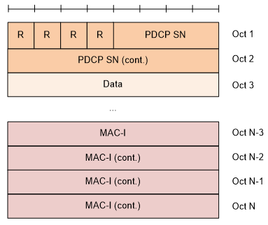
- Oct 1 holds four R bits and the first four bits of the PDCP SN.
- Oct 2 holds the rest of the SN, which makes 12 bits in total.
- Data starts at Oct 3, so the header costs two octets.
- MAC-I occupies the last four octets, Oct N-3 to Oct N.
- No D/C bit appears anywhere, so every SRB PDCP PDU is a data PDU.
Following shows the comparision between NR SRB PDCP and LTE SRB PDCP data structure. You will see that overall structure is same except that SN length in NR is much larger than LTE SRB PDCP.
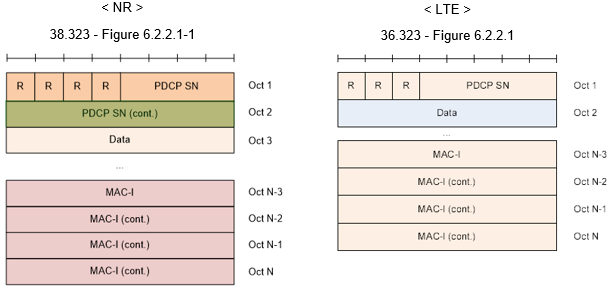
- NR spends 12 bits on the SN where LTE spends 5.
- LTE fits its SN inside Oct 1, so data starts at Oct 2. NR needs Oct 2 as well, so data starts at Oct 3.
- MAC-I is four octets in both, so the extra cost is one octet of header per PDU.
Data PDU for DRB
A DRB has the choices an SRB does not. It carries a D/C bit, because a DRB can send control PDUs as well as data. Its SN is either 12 or 18 bits, and its MAC-I is optional rather than always present.
The two SN lengths give two formats. The shorter one is first, and the only difference between them is how many octets the SN occupies before the data begins.
< 38.323 - Figure 6.2.2.2-1: PDCP Data PDU format with 12 bits PDCP SN >
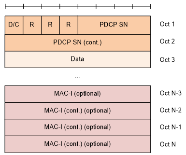
- Oct 1 holds the D/C bit, three R bits and the first four bits of the SN.
- Oct 2 holds the rest of the SN, and data starts at Oct 3.
- MAC-I is marked optional, which is the DRB integrity protection named at the top of this section.
< 38.323 - Figure 6.2.2.3-1: PDCP Data PDU format for DRBs with 18 bits PDCP SN >
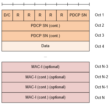
- Oct 1 holds the D/C bit, five R bits and only two bits of the SN.
- Oct 2 and Oct 3 carry the remaining sixteen bits, which makes 18.
- Data starts at Oct 4, so the longer SN costs one more octet on every PDU.
Two tables settle the two choices, and both are one line per value. The first reads the D/C bit, and the second says which bearers may use which SN length.
< 38.323 - Table 6.3.7-1: D/C field >

< 38.323 - Table 6.3.2-1: PDCP SN length >

- D/C is 0 for a control PDU and 1 for a data PDU.
- A 12 bit SN is allowed on UM DRBs, AM DRBs and SRBs.
- An 18 bit SN is allowed on UM DRBs and AM DRBs only, which is why the SRB format above has no second option.
Control PDU
A control PDU carries no user data at all. It is PDCP talking to the PDCP entity at the other end, and the PDU Type field says which of the two conversations it is. One is a status report, and the other is ROHC feedback travelling inside the PDCP stream.
The status report is the larger of the two, because it has to name a starting point and then a run of individual results.
< 38.323 - Figure 6.2.3.1-1: PDCP Control PDU format for PDCP status report >
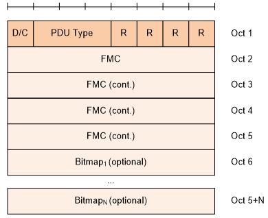
- Oct 1 holds the D/C bit, the PDU Type and four R bits.
- FMC occupies Oct 2 to Oct 5, so it is a four octet field.
- FMC is the First Missing COUNT. 38.323 defines it as the COUNT of the first missing PDCP SDU inside the reordering window, which is RX_DELIV.
- The bitmap is optional and runs from Oct 6 to Oct 5+N, so a status report with nothing to list is five octets long.
< 38.323 - Figure 6.2.3.2-1: PDCP Control PDU format for interspersed ROHC feedback >
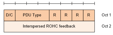
- The header is the same first octet as the status report, so the PDU Type is what tells the two apart.
- Oct 2 carries the feedback itself, and there is no bitmap and no FMC.
Three tables decode the fields above. The first two are shared with the data PDU formats, and the third gives the meaning of a single bit inside the status report bitmap.
< 38.323 - Table 6.3.7-1: D/C field >
< 38.323 - Table 6.3.8-1: PDU type >

< 38.323 - Table 6.3.10-1 Bitmap >

- D/C separates control from data, so it is read first on any PDU.
- PDU Type is 000 for a status report and 001 for interspersed ROHC feedback. Everything from 010 to 111 is reserved.
- A bitmap bit set to 0 means the SDU is missing, and 1 means it was received correctly.
- The COUNT a bit refers to is FMC plus the bit position, modulo 2 to the power 32. The bitmap is therefore read as an offset from FMC, not as absolute values.
Reference
[1] 38.323 v19.1.0 : NR - Packet Data Convergence Protocol (PDCP) specification. Every figure and table quoted on this page comes from it.
[2] 36.323 : E-UTRA - Packet Data Convergence Protocol (PDCP) specification. Figure 6.2.2.1 of this document is the LTE side of the SRB comparison above.