NCD SSB stands for Non Cell Defining SSB. Just from the word itself, you would guess there should be another comparative term 'CD SSB' meaning 'Cell Defining SSB'. Good guess !!! There IS the term CD SSB. What do these mean ? The definition of CD SSB and NCD SSB are as follows :
-
CD SSB : This is what we know as SSB in most of the situation. In most case, we just call it as SSB. It carries specific information like PCI and the location of SIB1 (meaning the SSB is associated with a SIB1). UE uses this SSB for cell detection and use it for initial attach. NCD SSB : This is specially designed for RedCap application. It carries most of the information as CD SSB except one important piece of information. That missing information is about SIB1. It mean that NCD SSB is not associated with SSB, implying that UE can use this for basic cell detection purpose like timing sync, RLM(Radio Link Measurement), BFD(Beam Failure Detection), but cannot use it for the initial attach because of missing SIB1 information.
Followings are the further details about NCD-SSB.
- Why NCD-SSB ?
- How to make an SSB without SIB1 information ?
- How does the MIB differ in an NCD-SSB ?
- UE Capability Information
- RRC Parameters
- Reference
- 3GPP Reference
Why NCD-SSB ?
Is NCD-SSB mandatory for all RedCap deployment ? NO. Is it possible for RedCap to operate even when there is no SSB at all within the Redcap BWP ? YES.
There are various scenarios (Cases) of allocating a spectrum for RedCap. In some scenario(case), it would be beneficial to use NCD-SSB for RedCap. It is just matter of benefit of using NCD SSB in some scenario.
Let's look into a few possible scenario (case) of allocating RedCap (these are just a few possible examples, not the exhaustive list of cases) and see how RedCap can operate in each of the scenario (
In this case, Initial DL BWP for RedCap is within Initial DL BWP for legacy UE, and there is no NCD-SSB is transmitted. In this scenario, the RedCap UE can use CD-SSB for every purpose (e.g, initial sync, initial attach, measurement (RLC, BFD etc) without any sacrifice of efficiency (e.g, switching back and forth between RedCap and legacy region). You may transmit NCD-SSB in this BWP allocation, but the benefit would not be that big.
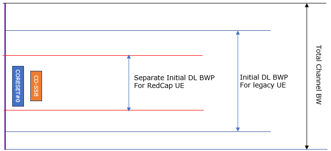
Figure 1. Case 1. The RedCap initial DL BWP already contains the CD-SSB, so nothing has to be added. An NCD-SSB is allowed in this layout, and there is little to gain from it.
- The outermost bracket is the total channel bandwidth.
- The blue bracket is the initial DL BWP for the legacy UE.
- The black bracket inside it is the separate initial DL BWP for the RedCap UE.
- CORESET#0 and CD-SSB sit at the left edge, inside both brackets. That is what makes this the easy case.
In this case, Initial DL BWP for RedCap is still within the Initial BWP for legacy UE but CD-SSB is outside of RedCap Initial BL BWP and there is no NCD SSB configured in the RedCap Initial DL BWP. In this scenario, RedCap UE needs to switch the frequency to other spectrum region (i.e, the spectrum where CD-SSB is located) whenever SSB is needed (e.g, time sync and measurement (RLM, BFD etc)).
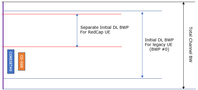
Figure 2. Case 2. The RedCap BWP has moved away from the CD-SSB and nothing replaces it. Every sync and every measurement now costs a retune.
- The RedCap initial DL BWP is the red pair of lines, near the top of the channel.
- CORESET#0 and CD-SSB are below it, inside the legacy BWP #0 and outside the RedCap BWP.
- Nothing is transmitted inside the RedCap BWP that the UE could synchronise on.
In this case, Initial DL BWP for RedCap is still within the Initial BWP for legacy UE but CD-SSB is outside of RedCap Initial BL BWP. However there IS NCD SSB configured in the RedCap Initial DL BWP. In this scenario, for initial attach the RedCap UE should still rely on CD-SSB because NCD-SSB does not carry any SIB1 information, but after the critical phase (i.e, upto Msg4 of RACH process) the RedCap UE utilize NCD-SSB for timing sync, measurement without switching back and forth between RedCap region and legacy region.
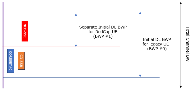
Figure 3. Case 3. The same BWP layout as Case 2, with an NCD-SSB added inside the RedCap BWP. The retuning disappears for everything except the initial attach.
- The NCD-SSB is the red block inside the RedCap initial DL BWP, now labelled BWP #1.
- CD-SSB and CORESET#0 stay where they were in Case 2, inside BWP #0.
- The NCD-SSB is at a different frequency from the CD-SSB, and absoluteFrequencySSB-r17 is the field that places it there.
- No CORESET#0 is drawn beside the NCD-SSB. That absence is the definition of a non cell defining SSB.
NCD-SSB is a convenience, not a requirement : Case 1 needs no NCD-SSB and Case 2 works without one. Only the cost changes.The cost that NCD-SSB removes is retuning : in Case 2 the UE leaves its own BWP for every sync and every measurement, and that is what Case 3 avoids.The initial attach still needs the CD-SSB : an NCD-SSB carries no SIB1 information, so Case 3 saves nothing before Msg4 of the RACH procedure.
How to make an SSB without SIB1 information ?
One of the key characteristics of NCD SSB would be stated as 'SSB that is not associated with SIB1' or 'SSB that does not carry information of SIB1'. How can we make SSB like this ? All SSB includes PBCH and the PBCH carries MIB. MIB always carries IE(Information Elements) about SIB1 information (i.e, the positioning information about CORESET 0). That being said, how is it possible to make SSB not associated with SIB1.
The simple answer is to set kSSB to out of range value. More specifically, set as described in 38.38.213-chapter 13 as below.
If a UE detects a first SS/PBCH block and determines that a CORESET for Type0-PDCCH CSS set is not present, and for 24 <≤ kSSB <≤ 29 for FR1 or for 12 <≤ kSSB <≤ 13 for FR2, the UE may determine the nearest (in the corresponding frequency direction) global synchronization channel number (GSCN) of a second SS/PBCH block having a CORESET for an associated Type0-PDCCH CSS set as NGSCN + Nsize Noffset Nreference. Here NGSCN is the GSCN of the first SS/PBCH block, NGSCN = 1 in FR1 and FR2-1, NGSCN = 3 in FR2-2, and Noffset is a GSCN offset provided by Table 13-16 for FR1 and Table 13-17 for FR2. If the UE detects an SS/PBCH block and the second SS/PBCH block does not provide a CORESET for Type0-PDCCH CSS as described in 38.213- 4.1, the UE may ignore the information related to GSCN of SS/PBCH block locations for performing cell search.
If a UE detects a SS/PBCH block and determines that a CORESET for Type0-PDCCH CSS set is not present, and for kSSB = 31 for FR1 or kSSB = 15 for FR2, the UE determines that there is no SS/PBCH block having an associated Type0-PDCCH CSS set within a GSCN range [NGSCNreference − Noffset , NGSCNreference + Noffset] where NGSCNreference and Noffset are respectively determined by controlResourceSetZero and searchSpaceZero in pdcch-ConfigSIB1. If the GSCN range is [NGSCNreference, NGSCNreference] the UE determines that there is no information for a second SS/PBCH block with a CORESET for an associated Type0-PDCCH CSS set on the detected SS/PBCH block.
If a UE does not detect any SS/PBCH block providing a CORESET for Type0-PDCCH CSS set, as described in 38.213-4.1, within a time period determined by the UE, the UE may ignore the information related to GSCN of SS/PBCH locations in performing cell search.
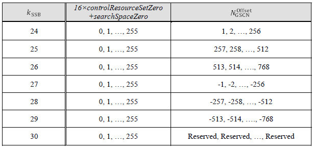
< 38.213 - Table 13-16: Mapping between the combination of kSSB and controlResourceSetZero and searchSpaceZero in pdcch-ConfigSIB1 to NGSCNOffsetfor FR1 >
< 38.213 - Table 13-17: Mapping between the combination of kSSB and controlResourceSetZero and searchSpaceZero in pdcch-ConfigSIB1 to NGSCNOffsetfor FR2 >
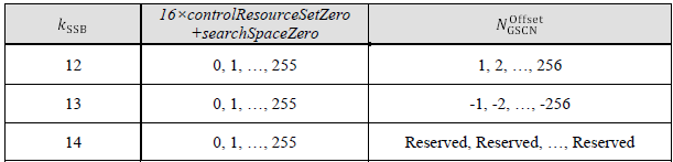
38.213 Table 13-17 is Table 13-16 with two rows instead of six. FR2 can point half as far in each direction, because it has one block of offsets per direction rather than three.
Both tables are read the same way, and the mechanism is easier to see than the paragraphs above make it look. The field kSSB is doing two jobs at once. It picks the direction to search in, and it picks which block of 256 GSCN steps the answer lies in.
The middle column is the same in every row, and that is the point of it. 16 x controlResourceSetZero + searchSpaceZero is an eight bit number from 0 to 255, and that number selects the position inside the block that kSSB chose. Two fields that normally say where CORESET#0 is are reused as a pointer, because on an NCD-SSB there is no CORESET#0 left to describe.
kSSB in FR1 |
Search direction |
NGSCNOffset that the eight bit number selects from |
24 |
upwards |
+1 to +256 |
25 |
upwards |
+257 to +512 |
26 |
upwards |
+513 to +768 |
27 |
downwards |
-1 to -256 |
28 |
downwards |
-257 to -512 |
29 |
downwards |
-513 to -768 |
30 |
- |
Reserved |
31 |
- |
No SS/PBCH block with an associated CORESET inside the indicated GSCN range |
kSSB in FR2 |
Search direction |
NGSCNOffset that the eight bit number selects from |
12 |
upwards |
+1 to +256 |
13 |
downwards |
-1 to -256 |
14 |
- |
Reserved |
15 |
- |
No SS/PBCH block with an associated CORESET inside the indicated GSCN range |
The last row of each table works differently from the others. For kSSB = 31 in FR1, or 15 in FR2, the same two fields are read again, but they describe a range rather than a position. Here controlResourceSetZero gives the reference GSCN and searchSpaceZero gives the offset, so the range extends by that offset in both directions. If the offset is zero the range collapses to one point, and the UE learns only that this particular SS/PBCH block carries no information about a second one.
The reach is not what the tables alone suggest, because the offset is scaled before it is applied. The GSCN of the target is the GSCN of the detected block, plus Nsize times the NGSCNOffset taken from the table. 38.213 sets Nsize to 1 in FR1, FR2-1 and FR2-NTN, and to 3 in FR2-2.
So FR1 reaches 768 GSCN steps in either direction and FR2-1 reaches 256, while FR2-2 also reaches 768 because every step there is worth three. A CD-SSB further away than that cannot be pointed at, and the UE has to find it by ordinary cell search.
The unit matters as much as the number. GSCN is a frequency raster index, and 38.104 Table 5.4.3.1-1 defines what one step is worth. The step is not constant across the ranges, so the same 768 offsets buy very different amounts of spectrum.
Frequency range |
SS block position SSREF |
GSCN |
One GSCN step |
0 to 3000 MHz |
N x 1200 kHz + M x 50 kHz, N = 1:2499, M in {1,3,5} |
3N + (M-3)/2 |
100 kHz or 1000 kHz in turn, averaging 400 kHz |
3000 to 24250 MHz |
3000 MHz + N x 1.44 MHz, N = 0:14756 |
7499 + N |
1.44 MHz |
24250 to 100000 MHz |
24250.08 MHz + N x 17.28 MHz, N = 0:4383 |
22256 + N |
17.28 MHz |
Put together, a pointer from an SS/PBCH block between 3 GHz and 24.25 GHz reaches about 1106 MHz in either direction. In FR2-1 it reaches about 4424 MHz, and in FR2-2 about 13271 MHz.
One thing the pointer does not carry is time. GSCN indexes a frequency raster and nothing else, so the mechanism says where to tune and stops there. A UE that follows it still has to acquire PSS and SSS at the new frequency in the ordinary way.
Timing for a configured NCD-SSB arrives from RRC instead, and in different units again. The field absoluteFrequencySSB-r17 is an ARFCN on the channel raster rather than a GSCN on the sync raster, and ssb-TimeOffset-r17 and ssb-Periodicity-r17 carry the time domain. The MIB pointer and the RRC configuration serve different readers, and a RedCap UE that has been configured never needs the pointer at all.
One detail has moved since the paragraphs above were quoted. 38.213 v19.4.0 groups FR1, FR2-1 and FR2-NTN together in that sentence, and FR2-NTN was added after this text was written.
An out of range kSSB is the whole mechanism : the MIB always carries the CORESET#0 fields. The only way to say that no SIB1 is here is to put a value in kSSB that cannot be a real subcarrier offset.24 to 29 point somewhere, 31 points nowhere : the first group tells the UE where to look for a CD-SSB. The last one tells it there is none within reach.The CORESET#0 fields become the pointer : 16 x controlResourceSetZero + searchSpaceZero is an eight bit offset inside the block that kSSB selected.The pointer has a limited reach : 768 GSCN steps in FR1 and FR2-2, and 256 in FR2-1. Nothing beyond that can be indicated.The pointer is frequency only : GSCN is a sync raster index, so the UE is told where to tune and has to acquire PSS and SSS there for itself.
How does the MIB differ in an NCD-SSB ?
The MIB is where you would expect to find the difference, and structurally there is none. There is no NCD-SSB variant of MIB, no field that disappears, and no shorter encoding. Every field below is transmitted in both cases. The whole distinction rests on the value of one of them, and on what that value does to a second one.
Following is based on
MIB ::=                             SEQUENCE {
                    systemFrameNumber                   BIT STRING (SIZE (6)),
                    subCarrierSpacingCommon             ENUMERATED {scs15or60, scs30or120},
                    ssb-SubcarrierOffset                INTEGER (0..15),
                    dmrs-TypeA-Position                 ENUMERATED {pos2, pos3},
                    pdcch-ConfigSIB1                    PDCCH-ConfigSIB1,
                    cellBarred                          ENUMERATED {barred, notBarred},
                    intraFreqReselection                ENUMERATED {allowed, notAllowed},
                    spare                               BIT STRING (SIZE (1))
                }
The two highlighted fields do all of the work. The other six are transmitted exactly as they would be in a CD-SSB, whether or not a UE has any use for them.
MIB field |
In a CD-SSB |
In an NCD-SSB |
systemFrameNumber |
The 6 MSB of the SFN. The 4 LSB travel in the PBCH transport block, outside the MIB encoding |
The same. It is the same cell, and ssb-TimeOffset-r17 is defined against the serving cell SFN 0, so the timing has to agree |
subCarrierSpacingCommon |
SCS for SIB1, Msg2, Msg4, MsgB, paging and broadcast SI messages |
Transmitted unchanged. A UE using this SSB never acquires SIB1 from it, so the value has nothing to act on |
The real kSSB, the frequency offset between the SSB and the resource block grid |
||
dmrs-TypeA-Position |
Position of the first DM-RS for downlink and uplink |
Transmitted unchanged, and unused for the same reason as subCarrierSpacingCommon |
controlResourceSetZero and searchSpaceZero, which together locate CORESET#0 |
||
cellBarred |
Whether the cell is barred, as defined in 38.304 |
38.331 gives no NCD-SSB specific rule. The out of range kSSB is already what stops a UE camping here |
intraFreqReselection |
Controls reselection to intra-frequency cells when the highest ranked cell is barred |
38.331 states plainly that this field is ignored by IAB-MT, NCR-MT and (e)RedCap UE |
spare |
One bit |
The same |
38.331 describes the mechanism from both ends, and the two field descriptions are worth reading together.
As an example, let's assume that a MIB decoded as below, Every MIB field is here, with the eight bits that 38.212 appends underneath it. The values are the ones the two worked examples use, so the pieces of ssb-SubcarrierOffset can be seen in the positions they actually occupy.
BCCH-BCH-Message, 24 bits, the part that the MIB encodes

  bits  field                                         value    binary
  ----  --------------------------------------------- -----  --------
     1  BCCH-BCH-MessageType, CHOICE, mib                           0
     6  systemFrameNumber, the 6 MSB of the SFN          11    001011
     1  subCarrierSpacingCommon                                     1
     4  ssb-SubcarrierOffset, the 4 LSB of kSSB           9      1001  <==
     1  dmrs-TypeA-Position                                         0
     4  pdcch-ConfigSIB1 : controlResourceSetZero         3      0011
     4  pdcch-ConfigSIB1 : searchSpaceZero                5      0101
     1  cellBarred                                                  1
     1  intraFreqReselection                                        0
     1  spare                                                       0
  ----
    24  total

Eight more bits, appended by 38.212 clause 7.1.1, outside the MIB

     1  4th LSB of the SFN                                          0
     1  3rd LSB of the SFN                                          1
     1  2nd LSB of the SFN                                          0
     1  1st LSB of the SFN                                          0
     1  half frame bit                                              0
     1  MSB of kSSB, in FR1                                         1  <==
     1  SS/PBCH block index bit, or reserved                        x
     1  SS/PBCH block index bit, or reserved                        x
  ----
     8  total, so the payload is 32 bits before the CRC and channel coding

Reading the two marked rows together
    kSSB  =  1  then  1001  =  11001  =  25

The same split on systemFrameNumber, in the opposite direction
    SFN   =  001011  then  0100  =  0010110100  =  180
Two things are visible here that no amount of prose makes obvious. The four bits of ssb-SubcarrierOffset and the MSB of kSSB are in different halves of the payload, and so are the two parts of the SFN. Neither field is contiguous, and the two fields split in opposite directions.
One caution about the order. 38.212 interleaves these 32 bits before transmission, using the pattern of its Table 7.1.1-1, so the layout above is the logical order of the payload rather than the order the bits go out in.
Two worked examples make the two directions concrete. Both start from the same detected block, placed on the global raster between 3 GHz and 24.25 GHz, where one GSCN step is worth 1.44 MHz.
Detected SS/PBCH block
    SSREF                                         = 3499.68 MHz
    GSCN                                          = 7846             ( 7499 + 347 )

MIB read from that block
    ssb-SubcarrierOffset, the five bit value kSSB, arrives in two pieces
        MSB, in the PBCH payload                  =  1     binary      1
        4 LSB, in the MIB                         =  9     binary   1001    INTEGER (0..15)
        the five bits together                    = 25     binary  11001    out of range, so SIB1 is absent

    controlResourceSetZero                        = 3
    searchSpaceZero                               = 5
    16 x controlResourceSetZero + searchSpaceZero = (16 x 3 + 5) = 53

38.213 Table 13-16, the row for kSSB = 25
    GSCN offset spans                               257 ... 512      upwards
    the value 53 selects                          = 257 + 53 = 310

Result
    Nsize in FR1                                  = 1
    target GSCN                                   = 7846 + 1 x 310 = 8156
    SSREF at that GSCN                            = 3000 MHz + ( 8156 - 7499 ) x 1.44 MHz
                                                  = 3946.08 MHz      446.4 MHz higher
The other value works the opposite way. It does not point at a block at all. It rules out a stretch of the raster, and the two fields are read separately rather than combined.
Detected SS/PBCH block
    GSCN                                          = 7846

MIB read from that block
    ssb-SubcarrierOffset, the five bit value kSSB, arrives in two pieces
        MSB, in the PBCH payload                  =  1     binary      1
        4 LSB, in the MIB                         = 15     binary   1111    INTEGER (0..15)
        the five bits together                    = 31     binary  11111    the 'nothing in range' value

    controlResourceSetZero                          gives the reference GSCN
    searchSpaceZero                                 gives the half width

Result
    no SS/PBCH block carrying a CORESET for Type0-PDCCH CSS set exists in
        [ reference - half width , reference + half width ]

    a half width of zero collapses the range to a single GSCN, and the block
    is then saying only that it carries no information about a second one
That second example leaves the reference and the half width symbolic on purpose. 38.213 says only that the two quantities are respectively determined by controlResourceSetZero and searchSpaceZero. The clause does not print that mapping the way Table 13-16 prints the offsets, so putting numbers on it here would be a guess.
So nothing is removed from the message. One field is set to a value that cannot be a real subcarrier offset, and that value re-tasks the eight bits sitting next to it.
There is one problem with that plan, and it explains a detail of the two mapping tables that is otherwise hard to account for. The field ssb-SubcarrierOffset is INTEGER (0..15), which is four bits. A value of 24 does not fit in four bits. 38.331 answers it in one line : the value range of this field may be extended by an additional most significant bit encoded within PBCH.
The MIB is not the whole PBCH payload, and two fields make use of that. The field systemFrameNumber keeps its 6 MSB in the MIB and puts its 4 LSB outside. The field ssb-SubcarrierOffset does the reverse, keeping its 4 LSB in the MIB and putting its MSB outside. Either way it is one field split across two carriers, not two separate values.
38.212 clause 7.1.1 shows where that bit lives. The PBCH payload carries timing related bits beyond the MIB, and how they are spent depends on how many candidate SS/PBCH block positions exist in a half frame. The list is the 4 LSB of the SFN, the half frame bit, and then either the MSB of kSSB or the higher bits of the SS/PBCH block index. Those are separate bits in the same payload, so the MSB in the examples above belongs to kSSB and not to the SFN.
Figure 4 puts the two cases side by side, so the payload bit that FR1 has free and FR2 does not can be compared directly.
Figure 4. Where the fifth bit of kSSB comes from. FR1 has a spare PBCH payload bit and FR2 does not, and that one difference is why the two mapping tables of 38.213 cover different value ranges.
- The four boxes at the top are ssb-SubcarrierOffset as the MIB encodes it. The MIB carries no more than those four bits.
- In FR1 the number of candidate SS/PBCH block positions in a half frame is small, so one payload bit is free. 38.212 assigns it the MSB of kSSB, which makes the field five bits and puts 24 to 31 in reach.
- In FR2 the same payload bits carry the 4th, 5th and 6th bits of the candidate SS/PBCH block index. Nothing is left over, so kSSB stays at four bits.
- The value ranges follow from that, and they are what 38.213 Table 13-16 and Table 13-17 had to fit inside.
The MIB structure is identical : there is no NCD-SSB variant, no field is omitted, and the encoded size is the same in both cases.One value changes, and it re-tasks a second field : an out of range ssb-SubcarrierOffset turns pdcch-ConfigSIB1 from a CORESET#0 locator into a GSCN pointer.The fifth bit of kSSB is not in the MIB : the field is INTEGER (0..15), and FR1 takes its extra MSB from the PBCH payload instead.The FR1 and FR2 ranges are a bit budget, not a preference : FR2 spends those payload bits on the SS/PBCH block index, so kSSB stays four bits there.An NCD-SSB is a complete SSB : PSS, SSS and PBCH are all transmitted, and PCI, ssb-PositionsInBurst and ssb-PBCH-BlockPower match the CD-SSB. What is absent is an association, not a signal.
UE Capability Information
UE can notiffy gNB on whether it support the capability of using NCD-SSB if availabel via the specific IEs in UE Capability Information message as listed below.
Following is based on
RedCapParameters-r17::= SEQUENCE {
-- R1 28-1: RedCap UE
supportOfRedCap-r17 ENUMERATED {supported} OPTIONAL,
supportOf16DRB-RedCap-r17 ENUMERATED {supported} OPTIONAL
}
RedCapParameters-v1740 ::= SEQUENCE {
ncd-SSB-ForRedCapInitialBWP-SDT-r17 ENUMERATED {supported} OPTIONAL
}
Following is based on
BandNR ::=                                SEQUENCE {
    bandNR                                    FreqBandIndicatorNR,
    ...                                                                                   -- the fields before the RedCap group are not NCD-SSB related
    -- R1 28-1a: RRC-configured DL BWP without CD-SSB or NCD-SSB
    bwp-WithoutCD-SSB-OrNCD-SSB-RedCap-r17    ENUMERATED {supported}                      OPTIONAL,
    -- R1 28-3: Half-duplex FDD operation type A for (e)RedCap UE
    halfDuplexFDD-TypeA-RedCap-r17            ENUMERATED {supported}                      OPTIONAL,
    -- R1 27-15b: Positioning SRS transmission in RRC_INACTIVE state configured outside initial UL BWP
    ...                                                                                   -- the remaining r17, r18 and r19 band fields are not NCD-SSB related
}
Two capability fields is fewer than it looks, because neither of them says "this UE supports NCD-SSB". Using an NCD-SSB in a dedicated DL BWP needs no capability of its own. The network configures nonCellDefiningSSB-r17 and the UE follows it.
ncd-SSB-ForRedCapInitialBWP-SDT-r17 is narrower than its name suggests. It is about small data transmission only. Without it, a UE can still use an NCD-SSB, but not for SDT in a RedCap-specific initial DL BWP that has one. The field also carries a dependency chain, because the UE has to declare supportOfRedCap-r17 and at least one of ra-SDT-r17 or cg-SDT-r17 beside it.
bwp-WithoutCD-SSB-OrNCD-SSB-RedCap-r17 covers the RRC-configured DL BWP rather than the initial one. It says the UE can operate in a dedicated BWP holding neither kind of SSB. Case 2 shows the same idea in the initial DL BWP, and this capability is what lets the network repeat it in a dedicated BWP once the UE is connected.
One practical note about where to look these up. The ASN.1 quoted here is defined in 38.331, in the UE capability information elements. 38.306 carries the prose descriptions of the same fields, which is the text reproduced above.
Neither field means "supports NCD-SSB" : using one in a dedicated BWP is a network configuration choice and needs no declared capability.The SDT capability has a dependency chain : ncd-SSB-ForRedCapInitialBWP-SDT-r17 requires supportOfRedCap-r17 and ra-SDT-r17 or cg-SDT-r17 alongside it.The no-SSB capability is about dedicated BWPs : it allows a configured DL BWP with neither a CD-SSB nor an NCD-SSB in it.The ASN.1 and its description are in different specs : 38.331 defines RedCapParameters-r17 and BandNR, and 38.306 describes what the fields mean.
RRC Parameters
Three information elements carry NCD-SSB between the network and the UE, and they sit in different places for different reasons. One configures it in a dedicated downlink BWP. One defines what an NCD-SSB actually is. The third carries it into RRC_INACTIVE, so that a UE doing small data transmission keeps the same reference after it has been suspended.
The listings are quoted at 38.331 v19.3.0. BWP-DownlinkDedicated and SuspendConfig have both grown Release 18 and Release 19 extension groups since NCD-SSB was introduced, and none of those new fields is NCD-SSB related.
Following is based on
BWP-DownlinkDedicated ::= SEQUENCE { pdcch-Config SetupRelease { PDCCH-Config } OPTIONAL, -- Need M pdsch-Config SetupRelease { PDSCH-Config } OPTIONAL, -- Need M sps-Config SetupRelease { SPS-Config } OPTIONAL, -- Need M radioLinkMonitoringConfig SetupRelease { RadioLinkMonitoringConfig } OPTIONAL, -- Need M ..., [[ sps-ConfigToAddModList-r16 SPS-ConfigToAddModList-r16 OPTIONAL, -- Need N sps-ConfigToReleaseList-r16 SPS-ConfigToReleaseList-r16 OPTIONAL, -- Need N sps-ConfigDeactivationStateList-r16 SPS-ConfigDeactivationStateList-r16 OPTIONAL, -- Need R beamFailureRecoverySCellConfig-r16 SetupRelease {BeamFailureRecoveryRSConfig-r16} OPTIONAL, -- Cond SCellOnly sl-PDCCH-Config-r16 SetupRelease { PDCCH-Config } OPTIONAL, -- Need M sl-V2X-PDCCH-Config-r16 SetupRelease { PDCCH-Config } OPTIONAL -- Need M ]], [[ preConfGapStatus-r17 BIT STRING (SIZE (maxNrofGapId-r17)) OPTIONAL, -- Cond PreConfigMG beamFailureRecoverySpCellConfig-r17 SetupRelease { BeamFailureRecoveryRSConfig-r16} OPTIONAL, -- Cond SpCellOnly harq-FeedbackEnablingforSPSactive-r17 BOOLEAN OPTIONAL, -- Need R cfr-ConfigMulticast-r17 SetupRelease { CFR-ConfigMulticast-r17 } OPTIONAL, -- Need M dl-PPW-PreConfigToAddModList-r17 DL-PPW-PreConfigToAddModList-r17 OPTIONAL, -- Need N dl-PPW-PreConfigToReleaseList-r17 DL-PPW-PreConfigToReleaseList-r17 OPTIONAL, -- Need NnonCellDefiningSSB-r17 NonCellDefiningSSB-r17 OPTIONAL, -- Need R servingCellMO-r17 MeasObjectId OPTIONAL -- Cond MeasObject-NCD-SSB ]], [[ tci-InDCI-r18 SetupRelease {TCI-InDCI-r18} OPTIONAL -- Need M ]], [[ sbfd-Config2-Reception-r19 ENUMERATED {enabled} OPTIONAL, -- Need S pathlossOffsetPRACH-DCI-1-0-r19 ENUMERATED { enabled } OPTIONAL, -- Need R prachAssociationDCI-1-0-r19 ENUMERATED { enabled } OPTIONAL -- Need R ]] }
Following is based on
NonCellDefiningSSB-r17 ::=      SEQUENCE {
    absoluteFrequencySSB-r17        ARFCN-ValueNR,
    ssb-Periodicity-r17             ENUMERATED { ms5, ms10, ms20, ms40, ms80, ms160, spare2, spare1 }       OPTIONAL,   -- Need S
    ssb-TimeOffset-r17              ENUMERATED { ms5, ms10, ms15, ms20, ms40, ms80, spare2, spare1 }      OPTIONAL,   -- Need S
    ...
}
The two fields are easier to hold together as a picture than as two paragraphs. Figure 5 draws both SSB trains against the same time axis, with a CD-SSB periodicity of 20 ms and an NCD-SSB configured at ms40 with a time offset of ms5.
Figure 5. The two SSB trains in time. The offset separates the NCD-SSB burst from the CD-SSB burst. The periodicity may only be made longer than the CD-SSB periodicity, so the NCD-SSB is always the sparser train.
- Each block is one SSB burst rather than one SSB. What a burst contains comes from ssb-PositionsInBurst, and the NCD-SSB inherits that field from the CD-SSB.
- ssb-TimeOffset-r17 is measured from the first CD-SSB burst transmitted after the first symbol of SFN 0. If the field is absent the offset is zero, and the two trains start together.
- ssb-Periodicity-r17 may only be longer than the CD-SSB periodicity. If the field is absent the NCD-SSB copies the CD-SSB periodicity.
- Everything not listed in NonCellDefiningSSB-r17 is inherited. PCI, ssb-PositionsInBurst and ssb-PBCH-BlockPower all come from the CD-SSB.
An NCD-SSB is a CD-SSB with three fields overridden : frequency, periodicity and time offset are configured, and every other property is inherited from the CD-SSB of the serving cell.The NCD-SSB is always the sparser train : only a periodicity longer than the CD-SSB periodicity may be configured, so it costs less overhead than a second full SSB would.Configuring it redirects the whole BWP : every other reference to an SSB in that BWP follows it, including QCL-Info, RadioLinkMonitoringRS, CFRA-SSB-Resource and PRACH-ResourceDedicatedBFR.SuspendConfig carries it into RRC_INACTIVE : ncd-SSB-RedCapInitialBWP-SDT-r17 keeps the same reference available for small data transmission after the UE is suspended.
Following is based on
SuspendConfig ::=                   SEQUENCE {
    fullI-RNTI                          I-RNTI-Value,
    shortI-RNTI                         ShortI-RNTI-Value,
    ran-PagingCycle                     PagingCycle,
    ran-NotificationAreaInfo            RAN-NotificationAreaInfo                          OPTIONAL,   -- Need M
    t380                                PeriodicRNAU-TimerValue                           OPTIONAL,   -- Need R
    nextHopChainingCount                NextHopChainingCount,
    ...,
    [[
    sl-UEIdentityRemote-r17             RNTI-Value                                        OPTIONAL,   -- Cond L2RemoteUE
    sdt-Config-r17                      SetupRelease { SDT-Config-r17 }                   OPTIONAL,   -- Need M
    srs-PosRRC-Inactive-r17             SetupRelease { SRS-PosRRC-Inactive-r17 }          OPTIONAL,   -- Need M
    ran-ExtendedPagingCycle-r17         ExtendedPagingCycle-r17                           OPTIONAL    -- Cond RANPaging
    ]],
    [[
    ncd-SSB-RedCapInitialBWP-SDT-r17    SetupRelease {NonCellDefiningSSB-r17}             OPTIONAL    -- Need M
    ]],
    [[
    resumeIndication-r18                ENUMERATED {true}                                 OPTIONAL,   -- Need N
    srs-PosRRC-InactiveEnhanced-r18     SetupRelease { SRS-PosRRC-InactiveEnhanced-r18 }  OPTIONAL,   -- Need M
    ran-ExtendedPagingCycleConfig-r18   ExtendedPagingCycleConfig-r18                     OPTIONAL,   -- Cond RANPaging
    multicastConfigInactive-r18         SetupRelease { MulticastConfigInactive-r18 }      OPTIONAL    -- Need M
    ]]
}
Reference
- What is NCD-SSB and why is it needed and what’s the use case here ?
- Cell Defininig SSB (CD-SSB)
- What is NCD-SSB and CD-SSB in REDCAP NR R17 ?
3GPP Reference
The four specifications below do different jobs, and it is worth knowing which one answers which question. 38.331 carries the ASN.1 quoted in this note. 38.306 carries the prose descriptions of the capability fields. 38.213 defines the kSSB mechanism and the two mapping tables. 38.300 gives the overall RedCap picture. The TDocs underneath are the RAN2 discussion that produced the three BWP cases.
- 38.300 - NR and NG-RAN Overall description
- 38 306 - User Equipment (UE) radio access capabilities
- 38.104 - NR; Base Station (BS) radio transmission and reception : 5.4.3 Synchronization raster
- 38.212 - NR; Multiplexing and channel coding : 7.1.1 PBCH payload generation
- 38.213 - NR;Physical layer procedures for control : 17.1 RedCap UE procedures
- 38.331 - NR;Radio Resource Control (RRC) : MIB, B.2 Description of BWP configuration options
- TDocs
- R2-2200190 : Discussions on RedCap-specific BWPs - Jan 17th – 25th January 2022
- R2-2200287 : Open issues on early identification, camping restrictions and NCD-SSB - Jan 17th – 25th January 2022
- R2-2200401 : BWP configuration for RedCap UE - Jan 17th – 25th January 2022
- R2-2200554 : Identification and access restriction of RedCap UE, and NCD-SSB related issues - Jan 17th – 25th January 2022
- R2-2200597 : Remaining issues on NCD SSB, identification and access for RedCap - Jan 17th – 25th January 2022
- R2-2200608 : On separate initial BWP and NCD-SSB for RedCap - Jan 17th – 25th January 2022
- R2-2200830 : Using NCD-SSB or CSI-RS in DL BWPs for RedCap UEs - Jan 17th – 25th January 2022
- R2-2200862 : Discussion on use of NCD-SSB or CSI-RS in DL BWPs for RedCap UE - Jan 17th – 25th January 2022
- R2-2201113 : RedCap UE power-saving aspects at cell re-selection - Jan 17th – 25th January 2022
- R2-2201461 : Aspects related to the use of NCD-SSB - Jan 17th – 25th January 2022
- R2-2201732 : Summary of NCD-SSB and Initial BWP aspects - Jan 17th – 25th January 2022
- R2-2201738 : NCD-SSB and Initial BWP aspects - Jan 17th – 25th January 2022