You may heard of MiniSlot in various 5G/NR related white papers and presentations even before 5G/NR 3GPP technical specification roll out. However, I still don't find any formal term 'MiniSlot' in 3GPP TS spec as of now (Jan 2019). It implies that 'MiniSlot' would not be the formal term even if it is possible to implement it.
Based on the white papers and presentations that I saw (Ref [1] for example), they define 'MiniSlot' as a slot that carries PDSCH or PUSCH with only a few symbol length(e.g, 2 symbols, 4 symbols etc) as illustrated below.
- How to implement MiniSlot ?
- Length of Minislot
- Why Minislot ?
- Design Consideration for Minislot
- Reference
How to implement MiniSlot ?
As of now(Jan 2019), I don't see any explicit description on MiniSlot implemenations in 3GPP spec. Probably we may see some when eMTC or URLLC related specification is fully specified even if they would not use the term 'MiniSlot'.
I think we can think of roughly two different ways to implement mini-slot as described below. But as of now (Mar 2020), I haven't found any explicit description on how to implement mini-slot in 3GPP (I might have missed the spec, it will be appreciated if any readers let me know if they managed to find the specification). ==> Recently (Mar 2021) one of the reader kindly let me know that there is some descriptions on the minislot in TR 38.912-8.1. I realized that this description was there since Rel 15 but I just didn't know about it.
In the current NR specifications, the mechanism is explicit even though the informal name remains useful. The time-domain resource assignment in scheduling DCI selects a configured row. For PDSCH, the row identifies K0, the start and length through SLIV or S and L, and the mapping type. PUSCH uses the corresponding K2, start, length, and mapping-type information. A short Type B allocation is the formal mechanism most often described as a mini-slot.
Transmit a DCI that schedule PDSCH with 2 or 4 symbols (using SLIV). In most of white papers, they show that DCI(PDSCH) symbol is directly followed by PDSCH. Also most of white paper illustrates that the DCI and PDSCH is located in the same slot (i.e, K0 = 0). But I think it is possible to schedule PDSCH in such way that DCI and PDSCH is not in the same slot(i.e, K0 is not Zero).
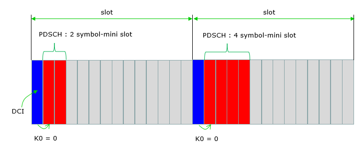
Figure 1. K0 = 0 places the two-symbol or four-symbol PDSCH in the scheduling slot, while SLIV identifies its exact symbol interval.
One of the extrem case of using Minislot (I think this would be the biggest motivation for minislot) is to achieve 'self-contained slot' which carrys PDCCH(DL Scheduling), PDSCH(DL data),PUCCH(HARQ ACK/NACK) within the same slot and it will greatly reduce physical layer latency.
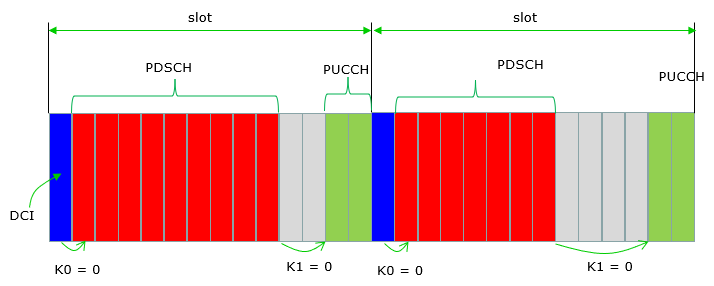
Figure 2. K0 = 0 and K1 = 0 remove slot offsets, but PDSCH processing and the DL-to-UL transition must still fit before PUCCH.
Like DL Minislot (PDSCH MiniSlot), we can transmit UL minislot(PUSCH minislot) in similar way as shown below.
Transmit a DCI that schedule PUSCH with 2 or 4 symbols (using SLIV). In most of white papers, they show that DCI(PUSCH) symbol is directly followed by PUSCH, but in practice it is likely to put one or more symbol gaps between DCI and PUSCH because switching between DL(DCI/PDCCH) and UL(PUSCH) without any guard period would be very challenging.
Also most of white paper illustrates that the DCI and PUSCH is located in the same slot (i.e, K2 = 0). But I think it is possible to schedule PDSCH in such way that DCI and PUSCH is not in the same slot(i.e, K2 is not Zero).
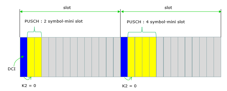
Figure 3. K2 = 0 places PUSCH in the scheduling slot, but the UE preparation time and the DL-to-UL guard constrain its earliest start.
DCI 2_0 does not schedule PDSCH or PUSCH. It dynamically indicates the slot format for a group of UEs. The actual data allocation still uses DCI 1_x or DCI 0_x together with the time-domain resource assignment. Therefore DCI 2_0 can make short DL or UL symbol regions available, but it is not a second data scheduling method.
Length of Minislot
How short the minislot can be ? The length of minislot is described in TR 38.912 as follows. The important point is that a mini-slot is measured in scheduled OFDM symbols, not as a new frame structure. Therefore its elapsed duration changes with the subcarrier spacing.
- At least above 6 GHz, mini-slot with length 1 symbol supported. ==> According to SLIV table defined in 3GPP specification, 1 symbol mini-slot is supported only for Uplink. For downlink, the shortest slot is 2 symbol length.
- Lengths from 2 to slot length - 1
- For URLLC, at least 2 is supported
For normal cyclic prefix, one slot contains 14 OFDM symbols. Its nominal duration is 1 ms / 2μ, where μ is the numerology index. Therefore a useful estimate for an L-symbol allocation is L / 14 × 1 ms / 2μ. Cyclic-prefix durations vary slightly between symbols, so this calculation is an engineering estimate rather than an exact waveform boundary.
| μ / SCS | Slot duration | 2-symbol estimate | 4-symbol estimate |
| 0 / 15 kHz | 1 ms | 142.9 µs | 285.7 µs |
| 1 / 30 kHz | 0.5 ms | 71.4 µs | 142.9 µs |
| 2 / 60 kHz | 0.25 ms | 35.7 µs | 71.4 µs |
| 3 / 120 kHz | 0.125 ms | 17.9 µs | 35.7 µs |
For example, a two-symbol allocation at 15 kHz occupies about one seventh of a 1 ms slot, or 142.9 µs. The same two symbols at 120 kHz occupy about 17.9 µs because the complete slot is only 125 µs. Therefore the number of symbols alone does not determine latency. Numerology, scheduling time, processing time, and feedback timing determine the complete result.
Downlink starts at two symbols : TS 38.214 permits Type B PDSCH lengths from two symbols with normal cyclic prefix.Uplink can use one symbol : TS 38.214 permits a one-symbol Type B PUSCH allocation.Duration depends on numerology : the same symbol count becomes shorter as subcarrier spacing increases.
Why Minislot ?
Why we need a special slot called mini-slot ? That is, what is the motivation for the mini-slot ? The motivation (use-case) for the mini-slot is described in TR 38.912-8.1 as follows.
- Support of very low latency including URLLC for certain slot lengths ==> I think this is the biggest motivation
- Target slot lengths are at least 1ms, 0.5ms.
- Support of finer TDM granularity of scheduling for the same/different UEs within a slot, especially if TRxP uses beam-sweeping (e.g., above 6GHz).
- NR-LTE co-existence, Note that this use case also exists for slot-based scheduling ==> See DSS page
- Forward compatibility towards unlicensed spectrum operation
With slot-based scheduling, an urgent transport block may wait for the next slot boundary. A Type B allocation can begin at a configured symbol instead. Therefore the waiting-time reduction can approach one slot when suitable symbols and a PDCCH occasion are available. This is the direct latency benefit, but it is not the complete radio latency.
The shorter interval also gives the scheduler finer time-domain granularity. An urgent UE can use a few symbols while another UE retains the remaining resources. However, a short allocation carries fewer resource elements. DM-RS and control overhead then consume a larger fraction of the transmission. Link adaptation, coding rate, and available bandwidth must still provide the required transport block and reliability.
Mini-slot reduces scheduling wait : data can start at a configured symbol instead of waiting for another slot boundary.Mini-slot does not define complete latency : PDCCH monitoring, decoding, UE processing, HARQ timing, and TDD direction changes remain.Finer granularity has an overhead cost : reference signals and control occupy a larger share of a very short allocation.
Design Consideration for Minislot
The base line consideration for the designing mini-slot is also described in TR 38.912 as follows. To me, it sound as if mini-slot is just a form of regular slot. That is, it is just a regular slot with very short symbol lengh. For all other aspect (e.g, DMRS, HARQ, DL control, UCI feedback etc) there is no difference between minislot and regular slot.
- Possible occurrence of mini-slot/slot transmission(s) occupying resources scheduled for ongoing slot transmission(s) of a given carrier for the same/different UEs
- DM-RS for mini-slot-level data channel is just a re-use of that for slot-level data channel
- DL control channel for mini-slot-level data scheduling is just a re-use of that for slot-level data scheduling
- UL control channel for mini-slot-level UCI feedback is just a re-use of that for slot-level UCI feedback
- Scheduling/HARQ timelines for a mini-slot can be based on scheduling/HARQ timelines for a slot
- Scheduling/HARQ timelines for a mini-slot can be based on scheduling/HARQ timelines shorter than those for a slot
Current NR implements this principle through the ordinary PDSCH and PUSCH procedures. TS 38.214 time-domain allocation selects K0 or K2, the start and length, and the mapping type. Type B permits the short non-slot allocation. Its DM-RS position follows the allocation so that channel estimation is available early enough for the short data region.
Zero slot offset is not the same as zero processing time. For the uplink case in Figure 3, the PUSCH must start late enough for the UE to decode the grant and prepare the transmission. The timing also includes timing advance and any DL-to-UL guard. For Figure 2, the selected K1 must place HARQ-ACK after the UE can process the PDSCH and prepare PUCCH.
A short urgent PDSCH may also overlap resources already assigned to another UE. When downlink pre-emption is configured, DCI format 2_1 identifies the interrupted time-frequency resources to the affected UE. This indication supports correct decoding and retransmission handling. It does not replace the scheduling DCI for the urgent PDSCH.
Type B is the usual mini-slot mapping : its start and length can describe a short region within a slot.Zero offset still has timing constraints : K0, K1, or K2 equal to zero only identifies the same slot.Direction changes require guard time : a same-slot PUSCH or PUCCH must respect UE switching and preparation limits.Pre-emption indication is separate : DCI 2_1 reports interrupted resources, while the normal scheduling DCI allocates data.
Reference
[1] Designing 5G NR (Qualcomm)
[2] 3GPP TR 38.912 5G;Study on New Radio (NR) access technology - 8.1 Numerologies and frame structure
[3] 3GPP TS 38.211 V19.4.0 : NR; Physical channels and modulation
[4] 3GPP TS 38.213 V19.4.0 : NR; Physical layer procedures for control
[5] 3GPP TS 38.214 V19.4.0 : NR; Physical layer procedures for data