LTM stands for L1/L2 Triggered Mobility. It is a mobility mechanism in which the UE is pre-configured by RRC with one or more candidate cell configurations, and the actual cell switch can then be triggered at lower layers or by configured execution conditions. Compared with a normal RRC handover that waits for a new RRC reconfiguration at the switching moment, LTM moves much of the target-cell preparation earlier.
The key idea is that RRC prepares the candidate configuration first, and L1/L2 measurements or MAC signaling later identify when a prepared candidate should be applied. This can reduce interruption time during a cell switch because the UE already has the candidate RRC configuration, measurement resources, TCI information, reset/security behavior, and optional early UL synchronization information.
- Signaling Overview
- L1/L2 Process
- LTM Protocol Sequence Examples
- Technical Challenges
- UE Capability
- RRC Parameters
- Reference
Signaling Overview
At a high level, LTM is configured by RRC and executed later by a lower-layer trigger or by configured execution conditions. The network sends ltm-Config or ltm-ConfigNRDC in RRCReconfiguration. The UE stores the candidate configurations and the serving-cell state values used to decide whether reset, timing alignment, or security update handling is needed during the switch.
The candidate cell can be associated with SSB or CSI-RS resources. The UE evaluates L1 or L3 conditions for the candidate, or receives an LTM cell switch command MAC CE from lower layers. When the trigger is satisfied, the UE applies the stored RRCReconfiguration contained in the selected LTM-Candidate.
Two decisions are taken before any of this signaling starts. The first is how many candidates to prepare. Each candidate costs RRC signaling and UE storage, so the network prepares the cells that the UE is likely to reach, and not every neighbour. The second decision is whether each candidate is sent complete or as a delta. A complete candidate carries a full RRCReconfiguration, and ltm-ConfigComplete marks it as such. A delta candidate omits the fields that already match the LTM reference configuration. That reduces the signaling, but it requires both sides to agree on which reference configuration applies.
The candidate configuration is stored, and it is not applied when it arrives. This separation is what distinguishes LTM from a normal handover. In a normal handover, the reconfiguration that changes the serving cell arrives at the moment of the change. In LTM, that reconfiguration arrived earlier, and only a short lower-layer indication is needed to apply it. The cost of the switch is therefore moved out of the switching moment, and into the preparation phase.
The serving-cell state values stored with the configuration decide how much of the protocol stack survives the switch. The UE compares the candidate no-reset ID with the serving-cell no-reset ID, and it skips MAC and RLC reset when the two match. The same comparison is made for the security-change ID, and for the UE-measured TA ID. Therefore the interruption cost of an LTM switch is not a fixed number. It depends on which of these comparisons succeed, and on whether the UE can transmit toward the target without Random Access.
The last step is the completion message on the target cell. Until that message is delivered, the network cannot be certain that the UE applied the intended candidate. This matters because the switch itself is triggered below RRC, and a MAC CE carries no RRC-level acknowledgement of its own. Therefore the completion message is the point where the two sides agree on which configuration is now active. Recovery behavior is defined for the case where it never arrives.
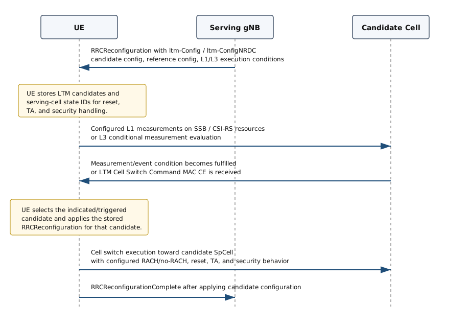
Configuration : The serving gNB configures one or more LTM candidates using LTM-Config. In NR-DC, LTM-ConfigNRDC can be used for SCG LTM and can include MCG-related configuration.Candidate storage : The UE stores candidate IDs, candidate PCI, candidate RRC configuration, SSB/CSI-RS measurement resources, optional TCI information, and optional early UL sync configuration.Execution condition : The trigger can come from lower layers, from an LTM cell switch command MAC CE, or from configured L1/L3 execution conditions.Cell switch : The UE selects the triggered candidate and applies the stored candidate RRCReconfiguration. The exact behavior depends on whether reset, UE-measured TA, and security-change IDs match the serving-cell state stored by the UE.Completion : After applying the target configuration, the UE completes the RRC reconfiguration procedure using the configured bearer/security behavior for the selected cell group.
L1/L2 Process
The name LTM emphasizes that the final mobility decision can be driven below RRC. RRC prepares the candidate cells and measurement/reporting rules, but the fast part is handled by L1 measurement and MAC procedures. In this sense, RRC provides the configuration, L1 provides beam/cell quality information, and MAC performs event evaluation, event reporting, and cell-switch command handling.
The L1/L2 part can be viewed as three related procedures: L1 beam-level measurement and reporting, conditional LTM event evaluation, and MAC CE based cell switch execution.
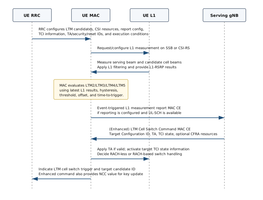
L1 Measurement and Event Triggered Report
The network may configure an RRC_CONNECTED UE to measure beam level quality for LTM candidate cells and/or the serving cell. The measured reference signal can be SS/PBCH block or CSI-RS, and the trigger quantity for event evaluation is L1-RSRP. MAC uses the latest L1 measurement results from lower layers after L1 filtering for event evaluation and reporting.
Measurement source : LTM candidate beams are represented by SSBRI for SSB based measurement or CRI for CSI-RS based measurement.Configured resource : The RRC LTM-CSI-ResourceConfig identifies which SSB, NZP CSI-RS, or CSI-IM resources belong to which LTM candidate ID.Report configuration : The RRC LTM-CSI-ReportConfig defines the event type, time-to-trigger, hysteresis, thresholds, candidate report list, report content, and optional periodic reporting after the event is triggered.Report delivery : When the event-triggered L1 measurement report is triggered and uplink resources are available, MAC includes the L1 measurement report MAC CE in UL-SCH.
LTM Events
TS 38.321 defines four LTM event types for L1 measurement/reporting. The same event family is also used when L1 measurement based conditional LTM is configured. The equations below use the same notation as the MAC specification: Ms is the serving beam measurement, Mn is the candidate beam measurement, Hys is hysteresis, Thresh is a threshold, and offsets are applied where configured.
Event |
Meaning |
Entering condition |
LTM2 |
Serving beam becomes worse than an absolute threshold. |
Ms + Hys < Thresh |
LTM3 |
Candidate beam becomes offset better than the serving beam. |
Mn + Obn - Hys > Ms + Obs + Off |
LTM4 |
Candidate beam becomes better than an absolute threshold. |
Mn + Obn - Hys > Thresh |
LTM5 |
Serving beam becomes worse than threshold1 and candidate beam becomes better than threshold2. |
Ms + Hys < Thresh1 and Mn + Obn - Hys > Thresh2 |
For leaving conditions, the inequality direction is reversed with hysteresis on the opposite side. For example, LTM2 leaves when Ms - Hys > Thresh, and LTM3 leaves when Mn + Obn + Hys < Ms + Obs + Off.
Conditional LTM
When L1 or L3 execution conditions are configured, the UE can trigger an LTM cell switch after the configured condition is fulfilled, without waiting for a new RRC message at that moment. For L1 based conditional LTM, MAC evaluates the LTM event conditions using L1 measurement results from lower layers. For L3 based conditional LTM, RRC evaluates the configured measurement IDs as described in the RRC procedure.
L1 condition : LTM-ExecutionCondition points to an LTM-CSI-ReportConfigId. MAC evaluates the related LTM event using candidate-cell and serving-cell L1 measurements.L3 condition : LTM-ExecutionCondition points to one or two MeasId values. RRC checks whether all configured events for that candidate are fulfilled.Candidate selection : If more than one candidate satisfies the condition, UE implementation selects one candidate for the LTM cell switch.Trigger indication : Once the condition is fulfilled, lower layers or RRC indicate the target candidate ID so that the stored candidate RRC configuration can be applied.
MAC CE Based Cell Switch
The network can also trigger the switch by sending an LTM Cell Switch Command MAC CE or an Enhanced LTM Cell Switch Command MAC CE. The MAC CE identifies the target candidate configuration and provides L2/L1 information needed at the switch point.
Target Configuration ID : Identifies the LTM candidate to apply. It corresponds to ltm-CandidateId - 1.Timing Advance Command : Provides TA for the target SpCell. If the value is valid, the UE can process the TA and perform a RACH-less LTM cell switch. If the value is FFF, no valid timing adjustment is available from the command.TCI state ID / UL TCI state ID : Activates the DL/joint TCI state and, when separate TCI is configured, the UL TCI state for the target cell.Contention-free RA resources : If the C field indicates presence, the MAC CE can include Random Access Preamble index, SUL/NUL selection, SS/PBCH index, PRACH Mask index, and Msg1 repetition number.Enhanced LTM Cell Switch Command : Adds the NCC value used for key update. It is used for MCG LTM when the target candidate requires a security key change according to the stored no-security-change ID comparison.
After receiving a valid LTM Cell Switch Command MAC CE on a serving cell, MAC indicates to upper layers that the LTM cell switch is triggered and provides the target configuration ID. If the enhanced command is used, MAC also provides the NCC value. Upper layers then apply the stored ltm-CandidateConfig for that candidate as part of the RRC reconfiguration with sync procedure.
Early DL Synchronization
The LTM Cell Switch Command is not always the first LTM MAC CE that the network sends for a candidate cell. Before it, the network can activate a TCI state that belongs to the candidate. The UE can then start downlink tracking on that candidate while the source cell is still serving it. This is called early DL synchronization, and it is the downlink counterpart of the early UL synchronization information stored with the candidate.
The reason this matters is the work the UE has to do immediately after the switch. Once the candidate configuration is applied, the UE has to decode PDCCH on the target cell. That requires time and frequency tracking for the target, and a valid beam assumption for it. If this work starts at the switch point, it happens inside the interruption. Therefore LTM allows part of it to be moved earlier.
The mechanism is the Candidate Cell TCI States Activation/Deactivation MAC CE, which uses one-octet eLCID codepoint 220. The candidate TCI states themselves are configured by RRC in ltm-TCI-Info inside LTM-Candidate. Each state carries a TCI state ID, one or two QCL information entries, and an optional pathloss reference RS ID. The MAC CE activates one or more of those states while the UE is still on the source cell. At the switch, the TCI state ID field in the LTM Cell Switch Command MAC CE selects which activated state applies to the target.
The activation has to arrive early enough to be useful. Therefore the trigger for it is configured separately from the cell switch trigger, and with a lower threshold. The trigger can be an L1-RSRP threshold with a report count, in the same form as the LTM4 event. It can also be an L3 RRC measurement report. The two thresholds are then chosen so that the TCI activation is sent before the cell switch command. A single threshold cannot serve both, because the activation would then arrive at the switching moment and save no tracking time.
A time axis makes the ordering clear. The candidate L1-RSRP rises as the UE moves toward the candidate cell. It crosses the early DL synchronization threshold first, and the cell switch threshold later. Each crossing triggers a different downlink MAC CE. The interval between the two crossings is where the early tracking work is done.
Early DL Synchronization Timeline
Early DL synchronization moves target-cell tracking and beam acquisition into the interval before the switch command. The interruption at the switch then covers the configuration change and the first target-cell transmission, and not the tracking.
Candidate TCI states : ltm-TCI-Info in LTM-Candidate carries the DL or joint TCI state list and the UL TCI state list for one candidate. Up to 128 LTM TCI states can be configured for one candidate, and the bound is maxNrofCandidateTCI-State-r18.Activation before the switch : The Candidate Cell TCI States Activation/Deactivation MAC CE, one-octet eLCID codepoint 220, activates candidate TCI states while the UE is still served by the source cell.Selection at the switch : The LTM Cell Switch Command MAC CE carries a TCI state ID field, and a UL TCI state ID field when separate TCI is configured. Those fields select which activated state applies to the target cell.Separate and earlier trigger : The activation uses its own threshold, and that threshold is lower than the cell switch threshold. Otherwise the activation arrives too late to remove any tracking time from the interruption.Measurement resources : Candidate-cell CSI-RS and CSI-IM resources are configured by ltm-NZP-CSI-RS-ResourceToAddModList and the related lists. SP CSI-RS/CSI-IM Resource Set Activation/Deactivation for Candidate Cell, one-octet eLCID codepoint 213, activates them during the same period.Relation to early UL sync : Early DL synchronization prepares reception on the candidate. The ltm-EarlyUL-SyncConfig information and the LTM Candidate Timing Advance Command prepare transmission toward it. The two are configured independently.
The same procedure can be read end to end, from the first candidate configuration to the completion message on the target cell. Early DL synchronization sits in the middle of that sequence, and it is the only phase in which the UE works on two cells at once. The highlighted band marks it.
LTM Signaling Sequence with Early DL Synchronization
Only two messages separate the prepared candidate from the applied one. Everything that can be done in advance, including the beam and tracking work of the highlighted band, is completed before the cell switch command is sent.
Preparation : RRC delivers the candidate configuration, the candidate TCI information, the LTM measurement resources, and the report configuration. The UE stores all of it and applies none of it.L1 measurement : The UE measures the candidate SSB or CSI-RS and reports L1-RSRP for the candidate beams. These reports drive both of the triggers that follow.Early DL synchronization : The network activates the candidate TCI state, and optionally the candidate CSI-RS resource set before it. The UE then tracks the candidate while the source cell continues to serve it.Cell switch : A later report satisfies the switch condition, and the LTM Cell Switch Command MAC CE names the candidate to apply. The stored configuration becomes the active one at this point.Execution on the target : The UE transmits on the target cell, either through PRACH or on a configured grant, and completes the RRC procedure there.
Three different TCI operations appear around an LTM cell switch, and they are easy to confuse. They differ in the cell they act on, and in the moment they act. The table below separates them.
Operation |
Acts on |
Signaling |
Purpose |
Unified TCI activation, Release 17 |
Serving cell |
Unified TCI States Activation/Deactivation MAC CE, one-octet eLCID 233 |
Activates the pool of unified TCI states that a DCI codepoint then selects from for the serving cell. |
Candidate cell TCI activation, Release 18 |
Candidate cell, before the switch |
Candidate Cell TCI States Activation/Deactivation MAC CE, one-octet eLCID 220 |
Lets the UE start DL tracking and beam refinement on a cell that is not serving it yet. |
TCI indication in the cell switch command |
Target cell, at the switch |
TCI state ID and UL TCI state ID fields of the (Enhanced) LTM Cell Switch Command MAC CE |
Indicates which state applies to the target cell when the stored candidate configuration is applied. |
The state format is shared, and that is the reason the three operations are easy to confuse. LTM-TCI-Info carries unifiedTCI-StateType, with the values separate and joint. A candidate is therefore described in the same terms that the Release 17 unified TCI framework uses for a serving cell. That framework is not part of LTM. It is used on a serving cell when no LTM candidate is configured at all. What LTM adds is the candidate-cell activation, and the timing rule that places it before the switch.
LCID / eLCID Values for LTM related MAC CE
The LTM specific MAC CEs are carried on DL-SCH using one-octet eLCID values. The tables below summarize the relevant LCID/eLCID tables from TS 38.321. Rows highlighted in yellow are directly related to LTM or LTM candidate-cell operation.
Table 6.2.1-1: Values of LCID for DL-SCH
Codepoint/Index |
LCID values |
0 | CCCH |
1-32 | Identity of the logical channel of DCCH, DTCH and multicast MTCH |
33 | Extended logical channel ID field (two-octet eLCID field) |
34 | Extended logical channel ID field (one-octet eLCID field) |
35-46 | Reserved |
47 | Recommended bit rate |
48 | SP ZP CSI-RS Resource Set Activation/Deactivation |
49 | PUCCH spatial relation Activation/Deactivation |
50 | SP SRS Activation/Deactivation |
51 | SP CSI reporting on PUCCH Activation/Deactivation |
52 | TCI State Indication for UE-specific PDCCH |
53 | TCI States Activation/Deactivation for UE-specific PDSCH |
54 | Aperiodic CSI Trigger State Subselection |
55 | SP CSI-RS/CSI-IM Resource Set Activation/Deactivation |
56 | Duplication Activation/Deactivation |
57 | SCell Activation/Deactivation (four octets) |
58 | SCell Activation/Deactivation (one octet) |
59 | Long DRX Command |
60 | DRX Command |
61 | Timing Advance Command |
62 | UE Contention Resolution Identity |
63 | Padding |
Table 6.2.1-1a: Values of two-octet eLCID for DL-SCH
Codepoint |
Index |
LCID values |
0 to (2^16 - 1) |
320 to (2^16 + 319) |
Identity of the logical channel |
Table 6.2.1-1b: Values of one-octet eLCID for DL-SCH
Codepoint |
Index |
LCID values |
0 to 207 | 64 to 271 | Reserved |
208 | 272 | On-demand SSB Activation/Deactivation (one octet Ci field) |
209 | 273 | On-demand SSB Activation/Deactivation (four octet Ci field) |
210 | 274 | SP CLI Measurement Resource Set Activation/Deactivation |
211 | 275 | UL Rate Control |
212 | 276 | Pathloss Offset Update |
213 | 277 | SP CSI-RS/CSI-IM Resource Set Activation/Deactivation for Candidate Cell |
214 | 278 | Enhanced LTM Cell Switch Command |
215 | 279 | LTM Candidate Timing Advance Command |
216 | 280 | Aggregated SP Positioning SRS Activation/Deactivation |
217 | 281 | Enhanced SP CSI reporting on PUCCH Activation/Deactivation |
218 | 282 | Cross-RRH TCI State Indication for UE-specific PDCCH |
219 | 283 | LTM Cell Switch Command |
220 | 284 | Candidate Cell TCI States Activation/Deactivation |
221 | 285 | PSI-Based SDU Discard Activation/Deactivation |
222 | 286 | Enhanced Unified TCI states Activation/Deactivation MAC CE for Joint TCI States |
223 | 287 | Enhanced Unified TCI states Activation/Deactivation MAC CE for Separate TCI States |
224 | 288 | NCR Access Link Beam Indication |
225 | 289 | NCR Downlink Backhaul Link Beam Indication |
226 | 290 | NCR Uplink Backhaul Link Beam Indication |
227 | 291 | Serving Cell Set based SRS TCI State Indication |
228 | 292 | SP/AP SRS TCI State Indication |
229 | 293 | BFD-RS Indication |
230 | 294 | Differential Koffset |
231 | 295 | Enhanced SCell Activation/Deactivation (one octet Ci field) |
232 | 296 | Enhanced SCell Activation/Deactivation (four octet Ci field) |
233 | 297 | Unified TCI States Activation/Deactivation |
234 | 298 | PUCCH Power Control Set Update for multiple TRP PUCCH repetition |
235 | 299 | PUCCH spatial relation Activation/Deactivation for multiple TRP PUCCH repetition |
236 | 300 | Enhanced TCI States Indication for UE-specific PDCCH |
237 | 301 | Positioning Measurement Gap Activation/Deactivation Command |
238 | 302 | PPW Activation/Deactivation Command |
239 | 303 | DL Tx Power Adjustment |
240 | 304 | Timing Case Indication |
241 | 305 | Child IAB-DU Restricted Beam Indication |
242 | 306 | Case-7 Timing advance offset |
243 | 307 | Provided Guard Symbols for Case-6 timing |
244 | 308 | Provided Guard Symbols for Case-7 timing |
245 | 309 | Serving Cell Set based SRS Spatial Relation Indication |
246 | 310 | PUSCH Pathloss Reference RS Update |
247 | 311 | SRS Pathloss Reference RS Update |
248 | 312 | Enhanced SP/AP SRS Spatial Relation Indication |
249 | 313 | Enhanced PUCCH Spatial Relation Activation/Deactivation |
250 | 314 | Enhanced TCI States Activation/Deactivation for UE-specific PDSCH |
251 | 315 | Duplication RLC Activation/Deactivation |
252 | 316 | Absolute Timing Advance Command |
253 | 317 | SP Positioning SRS Activation/Deactivation |
254 | 318 | Provided Guard Symbols |
255 | 319 | Timing Delta |
Index 278 / Codepoint 214 : Enhanced LTM Cell Switch Command, used when additional key update information such as NCC is needed.Index 279 / Codepoint 215 : LTM Candidate Timing Advance Command, used to provide TA for a CLTM candidate cell before switch execution.Index 283 / Codepoint 219 : LTM Cell Switch Command, the basic MAC CE that triggers applying a prepared LTM candidate configuration.Index 284 / Codepoint 220 : Candidate Cell TCI States Activation/Deactivation, used for TCI state handling of LTM candidate cells.
RACH-based and RACH-less Cases
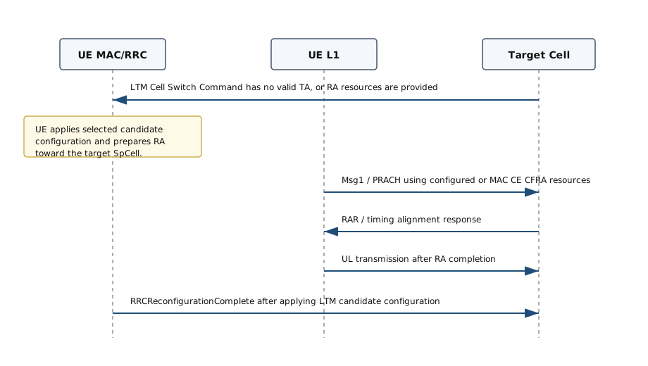
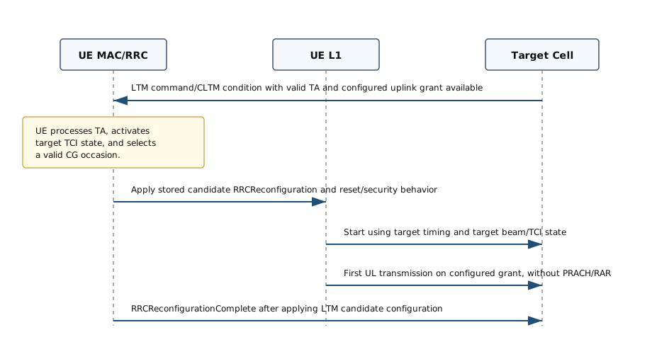
Whether the switch needs Random Access depends mainly on whether the UE already has enough uplink information to transmit toward the target cell immediately after applying the LTM candidate configuration. The most important item is valid timing alignment for the target SpCell. The TA may come from the LTM Cell Switch Command MAC CE, from an LTM Candidate Timing Advance Command MAC CE stored before the switch, or from UE-based TA measurement if that feature is configured and the measured TA is still valid.
Valid TA alone is not always sufficient. For a RACH-less switch, the UE also needs a usable uplink transmission opportunity for the target cell, such as a configured uplink grant associated with the LTM/CLTM target. In that case, the UE can transmit in the configured-grant occasion without first sending PRACH and without receiving a RAR PUSCH allocation. If valid TA or a valid configured-grant opportunity is not available, the UE has to perform Random Access on the target SpCell. The LTM Cell Switch Command MAC CE may provide contention-free RA information, such as preamble index, SSB index, PRACH mask index, SUL/NUL selection, and Msg1 repetition number, to make that Random Access procedure faster and more deterministic.
RACH-less LTM : Possible when valid TA is available and a configured uplink grant for the LTM target cell can be selected. The first UL transmission is performed in the available configured-grant occasion, not from a PUSCH grant delivered by RAR.RACH-based LTM : Used when Random Access is still needed. The LTM Cell Switch Command MAC CE may provide contention-free RA resources for the target cell.LTM Candidate Timing Advance Command : A separate MAC CE can provide TA for a CLTM candidate configuration before the switch. It identifies the candidate configuration ID and the TA command to apply during CLTM.
RACH-based LTM cell switch
RACH-less LTM cell switch
LTM Protocol Sequence Examples
Each LTM component has been described separately so far. A real trace shows all of them in one order, and that order is what makes the timing constraints visible. This section follows a single LTM cell switch from the initial candidate configuration to the completion message on the target cell. Every step names the message or the log line that carries it.
Example 1 : LTM triggered by LTM4 event
This example shows a RACH-based LTM execution where the UE is first configured with an LTM candidate cell and periodic L1-RSRP reporting. The candidate cell becomes strong enough to satisfy the LTM4 trigger condition. The gNB then sends the LTM Cell Switch Command MAC CE, the UE stops operation on the source cell, performs PRACH on the target cell, and completes the RRC reconfiguration on the target cell. The sequence below is based on the same key steps highlighted in Amarisoft TechAcademy NR SA LTM Test 1.
High Level Signaling Flow : LTM4-triggered RACH-based LTM
# |
Direction |
Protocol |
Message / Log |
Comment |
gNB -> UE |
RRC |
RRCReconfiguration |
The source cell configures LTM CSI reporting and candidate cell information. In this log, Candidate ID 1 points to PCI 502. |
|
UE -> gNB |
RRC |
RRCReconfigurationComplete |
The UE confirms that the LTM preconfiguration has been accepted and stored. |
|
UE -> gNB |
PHY / CSI |
Periodic ssb-Index-RSRP CSI |
The UE reports candidate-cell L1-RSRP using the configured LTM CSI report. The report improves from about -58 dBm to -44 dBm. |
|
gNB internal |
MAC |
LTM4 trigger condition met |
The configured LTM4 threshold/count condition is satisfied, so the gNB decides to issue an LTM switch command. |
|
gNB -> UE |
MAC CE |
LTM Cell Switch Command |
The MAC CE selects Target Config ID 0 and TCI state ID 3. No valid timing adjustment is available. |
|
gNB internal |
MAC |
UE stopped on source |
After the switch command is transmitted, the source-cell UE context is put into stopped state. |
|
UE -> Target gNB cell |
PHY / RACH |
PRACH on Cell 02 |
Because no valid target timing adjustment is available, the UE performs Random Access on the target cell. |
|
UE -> Target gNB cell |
RRC |
RRCReconfigurationComplete |
The UE completes the target-cell RRC procedure after access to the target cell. |
The source gNB sends RRCReconfiguration to prepare the UE before the actual mobility execution. The important part is that LTM CSI reporting is configured first, and then the candidate cell is configured under ltm-Config-r18. In this example, the candidate is ltm-CandidateId-r18 1 and the target physical cell is PCI 502. The complete RRCReconfiguration message is much longer because it also carries bearer and cell-group configuration; the block below shows the full LTM-related part from the decoded RRC message.
12:54:28.516 [RRC] DL 0001 01 DCCH-NR: RRC reconfiguration
{
  message c1: rrcReconfiguration: {
    rrc-TransactionIdentifier 0,
    criticalExtensions rrcReconfiguration: {
      ...
      csi-MeasConfig setup: {
        ltm-CSI-ReportConfigToAddModList-r18 {
          {
            ltm-CSI-ReportConfigId-r18 1,
            ltm-ResourcesForChannelMeasurement-r18 0,
            ltm-ReportConfigType-r18 periodic-r18: {
              reportSlotConfig-r18 slots80: 29,
              pucch-CSI-ResourceList-r18 {
                {
                  uplinkBandwidthPartId 0,
                  pucch-Resource 14
                }
              }
            },
            reportQuantity-r18 ssb-Index-RSRP-r18,
            reportFreqConfiguration-r18 {
              cqi-FormatIndicator-r18 widebandCQI-r18,
              pmi-FormatIndicator-r18 widebandPMI-r18,
              csi-ReportingBand-r18 subbands7-r18: '1111111'B
            },
            timeRestrictionForChannelMeasurements-r18 notConfigured,
            timeRestrictionForInterferenceMeasurements-r18 notConfigured,
            groupBasedBeamReporting-r18 disabled-r18: {
              nrofReportedRS-r18 n1
            }
          }
        }
      },
      nonCriticalExtension {
        nonCriticalExtension {
          nonCriticalExtension {
            ltm-Config-r18 setup: {
              ltm-CandidateToAddModList-r18 {
                {
                  ltm-CandidateId-r18 1,
                  ltm-CandidatePCI-r18 502,
                  ltm-SSB-Config-r18 {
                    ssb-Frequency-r18 626400,
                    subcarrierSpacing-r18 kHz30,
                    ssb-Periodicity-r18 ms20,
                    ssb-PositionsInBurst-r18 mediumBitmap: 'F0'H,
                    ss-PBCH-BlockPower-r18 -56
                  },
                  ltm-CandidateConfig-r18 {
                    rrc-TransactionIdentifier 0,
                    criticalExtensions rrcReconfiguration: {
                      radioBearerConfig { ... },
                      secondaryCellGroup octetstring: ...
                    }
                  },
                  ltm-ConfigComplete-r18 true,
                  ltm-TCI-Info-r18 {
                    ltm-DL-OrJointTCI-StateToAddModList-r18 {
                      {
                        tci-StateId-r18 0,
                        qcl-Type1-r18 {
                          referenceSignal-r18 ssb-Index: 0,
                          qcl-Type-r18 typeD
                        },
                        pathlossReferenceRS-Id-r18 0
                      },
                      {
                        tci-StateId-r18 1,
                        qcl-Type1-r18 {
                          referenceSignal-r18 ssb-Index: 1,
                          qcl-Type-r18 typeD
                        },
                        pathlossReferenceRS-Id-r18 1
                      },
                      {
                        tci-StateId-r18 2,
                        qcl-Type1-r18 {
                          referenceSignal-r18 ssb-Index: 2,
                          qcl-Type-r18 typeD
                        },
                        pathlossReferenceRS-Id-r18 2
                      },
                      {
                        tci-StateId-r18 3,
                        qcl-Type1-r18 {
                          referenceSignal-r18 ssb-Index: 3,
                          qcl-Type-r18 typeD
                        },
                        pathlossReferenceRS-Id-r18 3
                      }
                    }
                  }
                }
              },
              ltm-CSI-ResourceConfigToAddModList-r18 {
                {
                  ltm-CSI-ResourceConfigId-r18 0,
                  ltm-SSB-ResourceSet-r18 {
                    ltm-SSB-ResourceList-r18 { 0, 1, 2, 3 },
                    ltm-CandidateIdList-r18 { 1, 1, 1, 1 }
                  }
                }
              }
            }
          }
        }
      }
    }
  }
}
The UE responds with RRCReconfigurationComplete. This tells the gNB that the UE has accepted the configuration and can use the candidate configuration later when the MAC-layer LTM command is received.
12:54:28.535 [RRC] UL 0001 01 DCCH-NR: RRC reconfiguration complete
{
  message c1: rrcReconfigurationComplete: {
    rrc-TransactionIdentifier 0,
    criticalExtensions rrcReconfigurationComplete: {
    }
  }
}
After LTM CSI reporting is configured, the UE reports the target SSB RSRP periodically. The key indicators in these log lines are quantity=ssb-Index-RSRP, ltm=1, and the RSRP value. Early reports show about -58 dBm. Later reports show about -44 dBm, which satisfies the configured LTM4 condition in this test.
09:37:17.375 [PHY] UL 0001 01    -   385.9 CSI: type=periodic quantity=ssb-Index-RSRP cri=3 ltm=1 rsrp=-58
09:37:44.255 [PHY] UL 0001 01    -     1.9 CSI: type=periodic quantity=ssb-Index-RSRP cri=3 ltm=1 rsrp=-44
09:37:44.295 [PHY] UL 0001 01    -     5.9 CSI: type=periodic quantity=ssb-Index-RSRP cri=3 ltm=1 rsrp=-44
When the candidate measurement satisfies the LTM4 condition, the gNB moves from measurement monitoring to execution. In the log, this is explicitly printed as a MAC-layer decision to issue the LTM cell switch command.
12:55:31.080 [PHY] UL 0001 01 4601   925.9 PUCCH: format=4 prb=1 prb2=49 symb=0:14 occ=0 ack=1111 csi=111100111 epre=-57.0
12:55:31.080 [MAC] -  0001 01 LTM triggering condition is met, issue LTM cell switch command
The LTM execution is done by MAC CE, not by sending another handover-style RRC command at this moment. The MAC CE identifies the prepared target configuration and the TCI state to be applied. In this log, Target Config ID 0 selects the prepared target configuration and TCI state ID 3 points to the target beam/QCL information. The timing field says that no valid timing adjustment is available, so the UE cannot perform a purely RACH-less switch.
12:55:31.085 [MAC] DL 0001 01 LTM Cell Switch Cmd:0fff03 PAD:len=262
        LTM Cell Switch Command:
          Target Config ID: 0
          Timing Advance Command: no valid timing adjustment is available
          TCI state ID: 3
After the LTM command is transmitted, the gNB stops the UE operation on the source cell. This is the point where the UE is expected to leave the source-cell scheduling context and execute the prepared target-cell configuration.
12:55:31.091 [MAC] -  0001 01 LTM cell switch command transmitted
12:55:31.091 [MAC] -  0001  - set UE to stopped state
The LTM Cell Switch Command does not provide a valid timing adjustment in this case, so the UE accesses the target cell using PRACH. The target side is Cell 02, and the PRACH line also shows ssb_index=3, matching the selected TCI state / target SSB direction used for the switch.
12:55:31.106 [PHY] UL    - 02    -  927.19 PRACH: sequence_index=6 ta=5 prb=0:12 symb=2:12 ssb_index=3 snr=20.9 p=-33.4
12:55:31.106 [MAC] -  0003 02 Allocating new UE
12:55:31.109 [MAC] DL    - 02 RAR: rapid=6
        rapid=6
          ta=5
After Random Access on the target cell, the UE sends RRCReconfigurationComplete on Cell 02. This confirms that the UE has applied the target-side configuration and resumed operation through the target cell.
12:55:31.120 [RRC] UL 0002 02 DCCH-NR: RRC reconfiguration complete
{
  message c1: rrcReconfigurationComplete: {
    rrc-TransactionIdentifier 0,
    criticalExtensions rrcReconfigurationComplete: {
      nonCriticalExtension {
        nonCriticalExtension {
          nonCriticalExtension {
            needForGapsInfoNR-r16 {
              intraFreq-needForGap-r16 {
                {
                  servCellId-r16 0,
                  gapIndicationIntra-r16 no-gap
                }
              },
              interFreq-needForGap-r16 {
                {
                  bandNR-r16 78,
                  gapIndication-r16 gap
                }
              }
            }
          }
        }
      }
    }
  }
}
Technical Challenges
LTM reduces the delay of mobility execution by preparing the candidate cell configuration before the actual switch, but this shifts a number of difficult decisions from the switching moment to the configuration and lower-layer execution phase. The network has to prepare enough information for fast execution, while still avoiding premature switches, stale candidate configurations, wrong timing alignment, and unnecessary Random Access.
The main difficulty is that LTM crosses the boundary between RRC, MAC, and PHY. RRC owns the candidate configuration, MAC may deliver the actual switch command and timing-related commands, and L1 provides the fast measurements used for event evaluation. If these layers do not use a consistent view of the target cell, beam, timing, and security state, the UE may apply a valid stored configuration at the wrong time or toward the wrong target condition.
Measurement Reliability and False Triggers
LTM relies heavily on L1 measurements such as L1-RSRP over SSB or CSI-RS resources. These measurements can react quickly, but they can also fluctuate quickly due to beam sweeping, blockage, Doppler, measurement periodicity, and reporting delay. For this reason, the event condition cannot be treated as a simple instantaneous comparison.
Threshold and offset tuning : LTM2/LTM3/LTM4/LTM5 style conditions need proper threshold, offset, hysteresis, and time-to-trigger settings. Aggressive values reduce interruption but increase ping-pong risk.Serving-cell reference quality : The target candidate may look better only because the serving beam is temporarily blocked. The network may need to consider current serving-cell L1 reporting as well as candidate-cell reporting.Beam versus cell decision : A strong beam does not always mean that the target cell is the best mobility target. The target beam, TCI state, CSI-RS resource, and candidate cell identity have to remain aligned.
RACH-less Execution
RACH-less LTM is attractive because it avoids the PRACH, RAR, and contention-resolution steps, but it is only safe when the UE already has enough uplink information to transmit to the target cell. In practical terms, the UE needs valid timing alignment and a usable uplink transmission opportunity for the target cell, such as a configured grant or another configured UL resource that the network can monitor after the switch.
Timing alignment validity : TA may be delivered by the LTM Cell Switch Command MAC CE, by the LTM Candidate Timing Advance Command MAC CE, or by UE-based TA measurement. The challenge is deciding whether the value is still valid when the switch is executed.First UL transmission : Without RAR, the candidate cell does not allocate PUSCH dynamically during Random Access. The first UL transmission must use a pre-configured or otherwise already-known UL resource that the candidate cell is prepared to receive.Fallback behavior : If TA, configured grant, target TCI state, or required UL resource information is missing or expired, the UE should fall back to RACH-based execution or recovery behavior rather than attempting an undecodable uplink transmission.
Candidate Configuration Consistency
The stored LTM candidate configuration may be complete, or it may be a delta configuration that depends on a reference configuration. This reduces signaling overhead, but it also creates a consistency problem. The UE and network must have the same interpretation of the reference configuration, candidate ID, release list, no-reset ID, no-security-change ID, TCI information, and early UL synchronization information.
Stale candidates : A candidate that was valid when configured may become invalid after serving-cell reconfiguration, beam reconfiguration, carrier activation changes, or security/key changes.Delta configuration risk : A delta candidate is compact, but it is harder to validate because missing information is inherited from the reference configuration.Multiple candidates : When several candidate cells or execution conditions are configured, the UE and network need deterministic rules for selecting the triggered candidate and for releasing candidates that should no longer be used.
TCI, Beam, and UL Synchronization
For FR2 and beam-centric deployments, the cell switch is not only a cell-ID change. The UE also needs to know which DL and UL beam assumptions are valid after the switch. Candidate Cell TCI States Activation/Deactivation and related TCI state indication MAC CEs reduce this ambiguity, but the network must still coordinate them with measurement resources and switch timing.
DL reception after switch : The UE needs a valid PDCCH/PDSCH TCI state for the target cell so it can decode scheduling and data immediately after applying the candidate configuration.UL transmission after switch : For RACH-less operation, UL spatial relation, pathloss reference RS, and timing alignment have to be usable before the first UL transmission.Joint and separate TCI states : Networks supporting both joint and separate TCI state activation need to make sure the UE applies the intended DL and UL assumptions for the selected candidate.
Security, Reset, and State Handling
LTM attempts to avoid unnecessary protocol reset and security changes when the serving and candidate states are compatible, but it must still preserve security correctness. Release 19 adds more explicit support for key update handling, including enhanced cell switch command behavior with NCC. This is useful, but it increases the number of state combinations that have to be tested.
No-reset behavior : Avoiding MAC/RLC reset can reduce interruption, but the UE and network must agree which serving-cell and candidate-cell states can safely continue.No-security-change behavior : The no-security-change ID and related SK counter configuration have to match the intended security context, especially in NR-DC cases.Key update case : If key update is required during LTM, the MAC CE, RRC stored configuration, and PDCP/security processing order must be unambiguous.
NR-DC and Multi-Cell Operation
In NR-DC, LTM may apply to MCG, SCG, or combined operation depending on UE capability and network configuration. The complexity increases because the master node and secondary node may not have identical timing, measurement visibility, or security context ownership.
MCG and SCG separation : The network has to distinguish whether the LTM candidate belongs to MCG mobility, SCG mobility, SCG addition/change, or a dual-connectivity recovery case.Inter-node coordination : The node preparing the candidate cell must coordinate with the node that owns the relevant RRC, security, and bearer state.Bearer continuity : Low interruption requires PDCP/RLC/MAC state handling that matches the configured no-reset and security behavior.
Recovery and Test Coverage
The most important implementation rule is that LTM failure must not leave the UE in an ambiguous state. If the selected candidate cannot be applied, if the first target-cell transmission fails, or if the UE cannot decode the target-cell control channel after the switch, recovery behavior must be clearly specified and tested.
Recovery trigger : The UE needs clear criteria for declaring LTM failure, such as inability to apply the candidate configuration, TA invalidity, RACH-less UL failure, or target-cell control-channel failure.Return or re-establish : Depending on the failure point, recovery may mean falling back to RACH-based access, returning to the old serving cell if possible, or starting RRC re-establishment.Interoperability testing : Testing should cover complete versus delta candidate configuration, RACH-based versus RACH-less execution, key update versus no-security-change, MCG versus SCG operation, and multiple simultaneous candidate triggers.
UE Capability
The network should only configure an LTM feature that the UE has indicated as supported. The most direct UE capability indicators for LTM are in measurement/mobility capability IEs and in CA/PHY capability IEs that describe L1 measurement, reporting, TCI, and CSI-RS/CSI-IM support.
The following ASN snippets are extracted from 3GPP TS 38.331 V19.3.0. Only the fields directly related to LTM are shown; unrelated fields are collapsed with ....
Following is based on
MeasAndMobParameters ::=                    SEQUENCE {
    measAndMobParametersCommon              MeasAndMobParametersCommon              OPTIONAL,
    measAndMobParametersXDD-Diff            MeasAndMobParametersXDD-Diff            OPTIONAL,
    measAndMobParametersFRX-Diff            MeasAndMobParametersFRX-Diff            OPTIONAL
}

MeasAndMobParametersCommon ::=              SEQUENCE {
    ...
    [[
    -- R4 39-2a: SSB based inter-frequency L1-RSRP measurements with measurement gaps
    ltm-InterFreqMeasGap-r18                ENUMERATED {supported}                  OPTIONAL,
    dummy-ltm-FastUE-Processing-r18         SEQUENCE {
        fr1-r18                                 ENUMERATED {ms10, ms15},
        fr2-r18                                 ENUMERATED {ms10, ms15},
        fr1-AndFR2-r18                          ENUMERATED {ms20, ms30}
    }                                                                            OPTIONAL,
    ...
    ]],
    [[
    ltm-InterFreq-r18                       ENUMERATED {supported}                  OPTIONAL,
    ltm-MCG-NRDC-r18                        ENUMERATED {supported}                  OPTIONAL,
    ltm-RACH-LessDG-r18                     ENUMERATED {supported}                  OPTIONAL,
    ltm-RACH-LessCG-r18                     ENUMERATED {supported}                  OPTIONAL,
    ltm-Recovery-r18                        ENUMERATED {supported}                  OPTIONAL,
    ltm-ReferenceConfig-r18                 ENUMERATED {supported}                  OPTIONAL,
    ltm-MCG-NRDC-Release-r18                ENUMERATED {supported}                  OPTIONAL,
    -- R4 39-7: Faster UE processing time during cell switch
    ltm-FastUE-Processing-r18               SEQUENCE {
        fr1-r18                                 ENUMERATED {ms10, ms15}             OPTIONAL,
        fr2-r18                                 ENUMERATED {ms10, ms15}             OPTIONAL,
        fr1-AndFR2-r18                          ENUMERATED {ms20, ms30}             OPTIONAL
    }                                                                            OPTIONAL,
    ...
    ]],
    [[
    ltm-interFreqL1-OnlyInBC-r18            ENUMERATED {supported}                  OPTIONAL
    ]],
    [[
    ltm-KeyUpdateMCG-r19                    ENUMERATED {supported}                  OPTIONAL,
    ltm-KeyUpdateSCG-r19                    ENUMERATED {supported}                  OPTIONAL,
    cltm-EarlyTA-Indication-r19             INTEGER (1..8)                          OPTIONAL,
    cltm-ExecutionConditionL1-r19           ENUMERATED {supported}                  OPTIONAL,
    cltm-ExecutionConditionL3-r19           INTEGER (1..2)                          OPTIONAL,
    ltm-EventMeasAndReport-r19              ENUMERATED {supported}                  OPTIONAL,
    ltm-RecoveryWithKeyUpdate-r19           ENUMERATED {supported}                  OPTIONAL,
    ltm-MCG-SCG-AdditionOrChange-r19        ENUMERATED {supported}                  OPTIONAL,
    ...
    ltm-SR-ConfIdInCellSwitchCommand-r19    ENUMERATED {supported}                  OPTIONAL,
    ...
    ]]
}

CA-ParametersNR-v1830 ::=                   SEQUENCE {
    -- R1 45-1: Intra-frequency L1 measurement and reports for LTM
    intraFreqL1-MeasConfig-r18              SEQUENCE {
        supportedMaxIntraFreqCellsConfig-r18                INTEGER (1..8),
        supportedMaxIntraFreqCellsPerReport-r18             INTEGER (1..4),
        supportedMaxReportBeamsPerReportedCell-r18          INTEGER (1..4),
        supportedMaxReportBeamsReports-r18                  ENUMERATED {n1,n2,n3,n4,n6,n8,n9,n12,n16},
        supportedMaxAperiodic-LTM-CSI-ReportConfig-r18      INTEGER (0..4),
        supportedMaxPeriodic-LTM-CSI-ReportConfig-r18       INTEGER (1..4),
        supportedMaxSemiPersistent-LTM-CSI-ReportConfig-r18 INTEGER (0..4)
    }                                                                            OPTIONAL,
    -- R1 45-1a: Inter-frequency L1 measurement and reports for LTM
    interFreqL1-MeasConfig-r18              SEQUENCE {
        supportedMaxIntraInterFreqCellsConfig-r18           INTEGER (1..8),
        supportedMaxIntraInterFreqCellsPerReport-r18        INTEGER (1..4),
        supportedMaxIntraInterFreqBeamsPerCellReports-r18   INTEGER (1..4),
        supportedMaxIntraInterFreqBeamsReports-r18          ENUMERATED {n1,n2,n3,n4,n6,n8,n9,n12,n16}
    }                                                                            OPTIONAL,
    currentSpCellInclL1-Report-r18          ENUMERATED {supported}                  OPTIONAL,
    ...
}

CA-ParametersNR-v1900 ::=                   SEQUENCE {
    -- Network-triggered L1-RSRP measurement based on periodic CSI-RS for LTM
    intraFreqL1-MeasConfigPeriodicCSI-RS-r19    SEQUENCE {
        supportedMaxIntraFreqCellsConfig-r19                INTEGER (1..8),
        supportedMaxIntraFreqCellsPerReport-r19             INTEGER (1..4),
        supportedMaxReportBeamsPerReportedCell-r19          INTEGER (1..4),
        supportedMaxReportBeamsReports-r19                  ENUMERATED {n1,n2,n3,n4,n6,n8,n9,n12,n16},
        supportedMaxAperiodic-LTM-CSI-ReportConfig-r19      INTEGER (0..4),
        supportedMaxPeriodic-LTM-CSI-ReportConfig-r19       INTEGER (1..4),
        supportedMaxSemiPersistent-LTM-CSI-ReportConfig-r19 INTEGER (0..4)
    }                                                                            OPTIONAL,
    interFreqL1-MeasConfigPeriodicCSI-RS-r19    SEQUENCE {
        supportedMaxInterFreqCellsConfig-r19                INTEGER (1..8),
        supportedMaxInterFreqCellsPerReport-r19             INTEGER (1..4),
        supportedMaxReportBeamsPerReportedCell-r19          INTEGER (1..4),
        supportedMaxReportBeamsReports-r19                  ENUMERATED {n1,n2,n3,n4,n6,n8,n9,n12,n16},
        supportedMaxAperiodic-LTM-CSI-ReportConfig-r19      INTEGER (0..4),
        supportedMaxPeriodic-LTM-CSI-ReportConfig-r19       INTEGER (1..4),
        supportedMaxSemiPersistent-LTM-CSI-ReportConfig-r19 INTEGER (0..4)
    }                                                                            OPTIONAL,
    ...
}
ltm-InterFreqMeasGap / ltm-InterFreq : Indicates UE support for inter-frequency LTM measurement behavior, including whether measurement gaps are needed.ltm-MCG-NRDC : Indicates support for LTM related to the MCG in NR-DC operation.ltm-RACH-LessDG / ltm-RACH-LessCG : Indicates whether the UE supports LTM cell switch execution without RACH for delta or complete candidate configurations.ltm-Recovery / ltm-RecoveryWithKeyUpdate : Indicates support for recovery handling after LTM-related failure cases, including the Release 19 key-update case.ltm-ReferenceConfig : Indicates support for using a reference configuration with delta LTM candidate configurations.ltm-FastUE-Processing : Indicates the UE processing time supported during LTM cell switch execution for FR1, FR2, or combined FR1/FR2 operation.cltm-ExecutionConditionL1 / cltm-ExecutionConditionL3 : Indicates support for conditional LTM execution based on L1 or L3 conditions.ltm-EventMeasAndReport : Indicates support for LTM event measurement and event-triggered reporting.supportedMax...LTM-CSI-ReportConfig : Provides the supported maximum number of LTM CSI report configurations for aperiodic, periodic, and semi-persistent reporting.
The shape of this capability list is worth noticing. Most LTM capabilities are single supported flags, so the network learns only whether a feature can be used at all. A few carry numbers instead. The number of L3 execution conditions the UE can evaluate is given by cltm-ExecutionConditionL3-r19, and the LTM CSI report capabilities give the number of report configurations of each type.
Those numbers bound how many candidates the network can usefully prepare. A candidate that the UE cannot evaluate or report on is stored configuration and nothing more. Therefore the capability set has to be read before the candidate list is sized, and not after the candidates have been chosen.
RRC Parameters
The main RRC configuration entry point is RRCReconfiguration. In Release 18, the MCG LTM configuration is carried by ltm-Config-r18. In Release 19, NR-DC SCG LTM can be carried by ltm-ConfigNRDC-r19. The candidate itself is represented by LTM-Candidate, which can contain the target-cell RRC reconfiguration to apply when the LTM switch is triggered.
Following is based on
RRCReconfiguration-v1800-IEs ::= SEQUENCE {
...
ltm-Config-r18 SetupRelease {LTM-Config-r18} OPTIONAL, -- Need M
nonCriticalExtension RRCReconfiguration-v1830-IEs OPTIONAL
}
RRCReconfiguration-v1900-IEs ::= SEQUENCE {
...
ltm-ConfigNRDC-r19 SetupRelease {LTM-ConfigNRDC-r19} OPTIONAL, -- Need M
nonCriticalExtension SEQUENCE {} OPTIONAL
}
LTM-CandidateId-r18 ::= INTEGER (1..maxNrofLTM-Configs-r18)
LTM-Candidate-r18 ::= SEQUENCE {
ltm-CandidateId-r18 LTM-CandidateId-r18,
ltm-CandidatePCI-r18 PhysCellId OPTIONAL, -- Need M
ltm-SSB-Config-r18 LTM-SSB-Config-r18 OPTIONAL, -- Need M
ltm-CandidateConfig-r18 OCTET STRING (CONTAINING RRCReconfiguration) OPTIONAL, -- Need M
ltm-ConfigComplete-r18 ENUMERATED {true} OPTIONAL, -- Need R
ltm-EarlyUL-SyncConfig-r18 OCTET STRING (CONTAINING EarlyUL-SyncConfig-r18) OPTIONAL, -- Need R
ltm-EarlyUL-SyncConfigSUL-r18 OCTET STRING (CONTAINING EarlyUL-SyncConfig-r18) OPTIONAL, -- Need R
ltm-TCI-Info-r18 LTM-TCI-Info-r18 OPTIONAL, -- Need M
ltm-NoResetID-r18 INTEGER (1..maxNrofLTM-Configs-plus1-r18) OPTIONAL, -- Need M
ltm-UE-MeasuredTA-ID-r18 INTEGER (1..maxNrofLTM-Configs-plus1-r18) OPTIONAL, -- Need M
...,
[[
ltm-NoSecurityChangeID-r19 LTM-NoSecurityChangeId-r19 OPTIONAL, -- Need M
ltm-ExecutionCondition-r19 SetupRelease {LTM-ExecutionConditionList-r19} OPTIONAL, -- Need M
ltm-NZP-CSI-RS-ResourceToAddModList-r19
SEQUENCE (SIZE (1..maxNrofNZP-CSI-RS-Resources)) OF NZP-CSI-RS-Resource
OPTIONAL, -- Need N
ltm-NZP-CSI-RS-ResourceToReleaseList-r19
SEQUENCE (SIZE (1..maxNrofNZP-CSI-RS-Resources)) OF NZP-CSI-RS-ResourceId
OPTIONAL, -- Need N
ltm-NZP-CSI-RS-ResourceSetToAddModList-r19
SEQUENCE (SIZE (1..maxNrofNZP-CSI-RS-ResourceSets)) OF NZP-CSI-RS-ResourceSet
OPTIONAL, -- Need N
ltm-NZP-CSI-RS-ResourceSetToReleaseList-r19
SEQUENCE (SIZE (1..maxNrofNZP-CSI-RS-ResourceSets)) OF NZP-CSI-RS-ResourceSetId
OPTIONAL, -- Need N
ltm-CSI-ReportConfig-r19 SetupRelease {LTM-CSI-ReportConfig-r18} OPTIONAL, -- Need M
ltm-CSI-IM-ResourceToAddModList-r19
SEQUENCE (SIZE (1..maxNrofCSI-IM-Resources)) OF CSI-IM-Resource
OPTIONAL, -- Need N
ltm-CSI-IM-ResourceToReleaseList-r19
SEQUENCE (SIZE (1..maxNrofCSI-IM-Resources)) OF CSI-IM-ResourceId
OPTIONAL, -- Need N
ltm-CSI-IM-ResourceSetToAddModList-r19
SEQUENCE (SIZE (1..maxNrofCSI-IM-ResourceSets)) OF CSI-IM-ResourceSet
OPTIONAL, -- Need N
ltm-CSI-IM-ResourceSetToReleaseList-r19
SEQUENCE (SIZE (1..maxNrofCSI-IM-ResourceSets)) OF CSI-IM-ResourceSetId
OPTIONAL -- Need N
]]
}
LTM-SSB-Config-r18 ::= SEQUENCE {
ssb-Frequency-r18 ARFCN-ValueNR,
subcarrierSpacing-r18 SubcarrierSpacing,
ssb-Periodicity-r18 ENUMERATED {ms5, ms10, ms20, ms40, ms80,
ms160, spare2, spare1} OPTIONAL, -- Need S
ssb-PositionsInBurst-r18 CHOICE {
shortBitmap BIT STRING (SIZE (4)),
mediumBitmap BIT STRING (SIZE (8)),
longBitmap BIT STRING (SIZE (64))
} OPTIONAL, -- Need R
ss-PBCH-BlockPower-r18 INTEGER (-60..50) OPTIONAL, -- Need R
...
}
LTM-TCI-Info-r18 ::= SEQUENCE {
ltm-DL-OrJointTCI-StateToAddModList-r18
SEQUENCE (SIZE (1..maxNrofCandidateTCI-State-r18)) OF CandidateTCI-State-r18
OPTIONAL, -- Need N
ltm-DL-OrJointTCI-StateToReleaseList-r18
SEQUENCE (SIZE (1..maxNrofCandidateTCI-State-r18)) OF TCI-StateId
OPTIONAL, -- Need N
ltm-UL-TCI-StateToAddModList-r18 SEQUENCE (SIZE (1..maxNrofCandidateUL-TCI-r18)) OF CandidateTCI-UL-State-r18
OPTIONAL, -- Need N
ltm-UL-TCI-StateToReleaseList-r18 SEQUENCE (SIZE (1..maxNrofCandidateUL-TCI-r18)) OF TCI-UL-StateId-r17
OPTIONAL, -- Need N
ltm-NZP-CSI-RS-ResourceToAddModList-r18
SEQUENCE (SIZE (1..maxNrofNZP-CSI-RS-Resources)) OF NZP-CSI-RS-Resource
OPTIONAL, -- Need N
ltm-NZP-CSI-RS-ResourceToReleaseList-r18
SEQUENCE (SIZE (1..maxNrofNZP-CSI-RS-Resources)) OF NZP-CSI-RS-ResourceId
OPTIONAL, -- Need N
ltm-NZP-CSI-RS-ResourceSetToAddModList-r18
SEQUENCE (SIZE (1..maxNrofNZP-CSI-RS-ResourceSets)) OF NZP-CSI-RS-ResourceSet
OPTIONAL, -- Need N
ltm-NZP-CSI-RS-ResourceSetToReleaseList-r18
SEQUENCE (SIZE (1..maxNrofNZP-CSI-RS-ResourceSets)) OF NZP-CSI-RS-ResourceSetId
OPTIONAL, -- Need N
pathlossReferenceRS-ToAddModList-r18
SEQUENCE (SIZE (1..maxNrofPathlossReferenceRSs-r17)) OF PathlossReferenceRS-r17
OPTIONAL, -- Need N
pathlossReferenceRS-ToReleaseList-r18
SEQUENCE (SIZE (1..maxNrofPathlossReferenceRSs-r17)) OF PathlossReferenceRS-Id-r17
OPTIONAL, -- Need N
unifiedTCI-StateType-r18 ENUMERATED {separate, joint} OPTIONAL, -- Need R
...
}
CandidateTCI-State-r18 ::= SEQUENCE {
tci-StateId-r18 TCI-StateId,
qcl-Type1-r18 LTM-QCL-Info-r18,
qcl-Type2-r18 LTM-QCL-Info-r18 OPTIONAL, -- Need R
pathlossReferenceRS-Id-r18 PathlossReferenceRS-Id-r17 OPTIONAL, -- Cond Joint
tag-Id-ptr-r18 ENUMERATED {n0,n1} OPTIONAL, -- Cond 2TA
ul-PowerControl-r18 Uplink-powerControlId-r17 OPTIONAL, -- Cond Joint2
...
}
LTM-QCL-Info-r18 ::= SEQUENCE {
referenceSignal-r18 CHOICE {
ssb-Index SSB-Index,
csi-RS-Index NZP-CSI-RS-ResourceId
},
qcl-Type-r18 ENUMERATED {typeA, typeB, typeC, typeD},
...
}
LTM-Config-r18 ::= SEQUENCE {
ltm-ReferenceConfiguration-r18 SetupRelease {ReferenceConfiguration-r18} OPTIONAL, -- Need M
ltm-CandidateToReleaseList-r18 SEQUENCE (SIZE (1..maxNrofLTM-Configs-r18))
OF LTM-CandidateId-r18 OPTIONAL, -- Need N
ltm-CandidateToAddModList-r18 SEQUENCE (SIZE (1..maxNrofLTM-Configs-r18))
OF LTM-Candidate-r18 OPTIONAL, -- Need N
ltm-ServingCellNoResetID-r18 INTEGER (1..maxNrofLTM-Configs-plus1-r18) OPTIONAL, -- Need N
ltm-CSI-ResourceConfigToAddModList-r18
SEQUENCE (SIZE (1..maxNrofLTM-CSI-ResourceConfigurations-r18))
OF LTM-CSI-ResourceConfig-r18 OPTIONAL, -- Need N
ltm-CSI-ResourceConfigToReleaseList-r18
SEQUENCE (SIZE (1..maxNrofLTM-CSI-ResourceConfigurations-r18))
OF LTM-CSI-ResourceConfigId-r18 OPTIONAL, -- Need N
attemptLTM-Switch-r18 ENUMERATED {true} OPTIONAL, -- Cond LTM-MCG
ltm-ServingCellUE-MeasuredTA-ID-r18 INTEGER (1..maxNrofLTM-Configs-plus1-r18) OPTIONAL, -- Need N
...,
[[
ltm-ServingCellNoSecurityChangeID-r19 LTM-NoSecurityChangeId-r19 OPTIONAL, -- Need N
ltm-ServingCellExecutionCondition-r19 CHOICE {
release NULL,
setup LTM-ExecutionConditionList-r19
} OPTIONAL -- Need N
]]
}
LTM-ConfigNRDC-r19 ::= SEQUENCE {
ltm-ConfigurationSCG-r19 LTM-Config-r18 OPTIONAL, -- Need M
ltm-SK-CounterConfigToAddModList-r19 SEQUENCE (SIZE (1..maxSecurityCellSet-r18))
OF SK-CounterConfigLTM-r19 OPTIONAL, -- Need N
ltm-SK-CounterConfigToReleaseList-r19
SEQUENCE (SIZE (1..maxSecurityCellSet-r18))
OF LTM-NoSecurityChangeId-r19 OPTIONAL, -- Need N
...
}
LTM-CSI-ReportConfig-r18 ::= SEQUENCE {
ltm-CSI-ReportConfigId-r18 LTM-CSI-ReportConfigId-r18,
ltm-ResourcesForChannelMeasurement-r18 LTM-CSI-ResourceConfigId-r18,
ltm-ReportConfigType-r18 CHOICE {
periodic-r18 SEQUENCE { ... },
semiPersistentOnPUCCH-r18 SEQUENCE { ... },
semiPersistentOnPUSCH-r18 SEQUENCE { ... },
aperiodic-r18 SEQUENCE { ... },
...,
eventTriggered-r19 SEQUENCE {
eventId-r19 CHOICE {
eventLTM2-r19 SEQUENCE { ... },
eventLTM3-r19 SEQUENCE { ... },
eventLTM4-r19 SEQUENCE { ... },
eventLTM5-r19 SEQUENCE { ... },
...
},
eventTriggeredReportConfig-r19 SEQUENCE { ... } OPTIONAL,
...
}
},
ltm-ReportContent-r18 LTM-ReportContent-r18,
...
}
LTM-ExecutionConditionList-r19 ::= SEQUENCE (SIZE (1..maxNrofLTM-Configs-r18))
OF LTM-ExecutionCondition-r19
LTM-ExecutionCondition-r19 ::= SEQUENCE {
ltm-CandidateId-r19 LTM-CandidateId-r18,
executionCondition-r19 CHOICE {
l1-Conditions-r19 LTM-CSI-ReportConfigId-r18,
l3-Conditions-r19 SEQUENCE (SIZE (1..2)) OF MeasId
} OPTIONAL, -- Need R
...
}
ltm-Config-r18 : Main RRC container for LTM on the MCG. It adds, modifies, releases, and triggers candidate configurations.ltm-ConfigNRDC-r19 : NR-DC container for SCG LTM. It wraps an SCG LTM configuration and security counter configuration for no-security-change operation.ltm-CandidateConfig-r18 : Holds the RRCReconfiguration that the UE applies when the candidate is selected for LTM cell switch execution.ltm-ConfigComplete-r18 : Indicates whether the candidate configuration is complete. If it is absent, the UE uses the LTM reference configuration and applies the candidate as a delta configuration.ltm-CandidatePCI-r18 : Identifies the physical cell ID of the candidate SpCell.ltm-SSB-Config-r18 : Provides SSB frequency, SCS, periodicity, burst positions, and SSB power used for candidate-cell measurement.ltm-TCI-Info-r18 : Carries the beam information for one candidate. It holds the DL or joint TCI state list, the UL TCI state list, the candidate NZP CSI-RS resources, and the pathloss reference RS list. The field unifiedTCI-StateType-r18 selects joint or separate DL/UL operation for that candidate.CandidateTCI-State-r18 : One candidate TCI state. It gives a TCI state ID, one or two QCL information entries, and optional pathloss reference RS, TAG pointer, and uplink power control identity. These are the states that the Candidate Cell TCI States Activation/Deactivation MAC CE activates before the switch.ltm-NZP-CSI-RS-Resource... / ltm-CSI-IM-Resource... : Release 19 adds per-candidate CSI-RS and CSI-IM resource lists to LTM-Candidate. They configure the candidate-cell resources used for LTM measurement and for downlink tracking before the switch.ltm-CSI-ResourceConfig... : Configures SSB, NZP CSI-RS, or CSI-IM resources used for LTM measurement and reporting.ltm-CSI-ReportConfig-r18 : Configures scheduled or event-triggered LTM measurement reporting. Release 19 adds LTM2/LTM3/LTM4/LTM5 event choices.ltm-ServingCellExecutionCondition-r19 : Configures serving-cell execution conditions for MCG LTM.LTM-ExecutionConditionList-r19 : Maps a candidate ID to either L1 conditions using an LTM CSI report configuration ID or L3 conditions using one or two measurement IDs.ltm-NoResetID / ltm-ServingCellNoResetID : Controls whether radio/RLC reset behavior can be avoided across the LTM switch when candidate and serving-cell IDs match.ltm-UE-MeasuredTA-ID / ltm-ServingCellUE-MeasuredTA-ID : Controls whether UE-based timing advance measurements are associated with a candidate.ltm-NoSecurityChangeID / ltm-ServingCellNoSecurityChangeID : Controls whether a security key change is needed during the LTM switch.
Reference
- 3GPP TS 38.331 V19.3.0, Radio Resource Control (RRC) protocol specification.
- 3GPP TS 38.321, Medium Access Control (MAC) protocol specification.
- 3GPP TS 38.213, Physical layer procedures for control.
- 3GPP TS 38.214, Physical layer procedures for data.
- 3GPP TS 38.322, Radio Link Control (RLC) protocol specification.
- 3GPP TS 38.323, Packet Data Convergence Protocol (PDCP) specification.