Rel-8 gave LTE exactly one place to put a downlink scheduling assignment. The control region is the first one, two or three OFDM symbols of a subframe. It spans the whole carrier, and every UE in the cell shares it. That design has served LTE well, but it has a hard ceiling. You cannot make the region taller than three symbols, and you cannot reserve part of it for one UE.
Rel-11 added a second place. The new channel, ePDCCH, sits inside the PDSCH region, in resource blocks the network picks for each UE, and it is built from its own resource units called eREG and eCCE. The network can therefore schedule more UEs in one subframe, keep a UE's control channel away from the interference its neighbours generate, and beamform a control channel the way it already beamforms data.
Let's start with the motivation, then follow the structure downwards from the resource element to the finished ePDCCH, and finish with the RRC fields that configure it.
Followings are the topics to be covered in this page.
- Why eCCE/ePDCCH ?
- Can we complete remove the CFI overhead ?
- Resource Allocation for ePDCCH
- eREG to RE Mapping
- How are eREG, eCCE and ePDCCH related ?
- Where does the UE look for ePDCCH ?
- RRC Aspect of eCCE/ePDCCH
- Reference
Why eCCE/ePDCCH ?
eCCE/ePDCCH is a new type of resource allocation for contron channel information. In engineering, when we introduce anything new, usually we would have some reason (or motivation) on why we need the new things. Same thing applies to eCCE/ePDCCH. So our first question would be 'why we need this new type of resource allocation ?'.
Main reason (motivation) would be illustrated as below and we may have some additional advantage as a result of adopting this new method.
The diagram below sets out the Rel-8 starting point and the two answers that were proposed to it. The top box holds the four numbers that fix the ceiling. A REG is 4 resource elements, a CCE is 9 REGs, an aggregation level is 1, 2, 4 or 8 CCEs, and the control region is at most 3 OFDM symbols. Those four numbers together decide how many scheduling assignments one subframe can carry, and the Rel-11 features in the box below them need more than that.
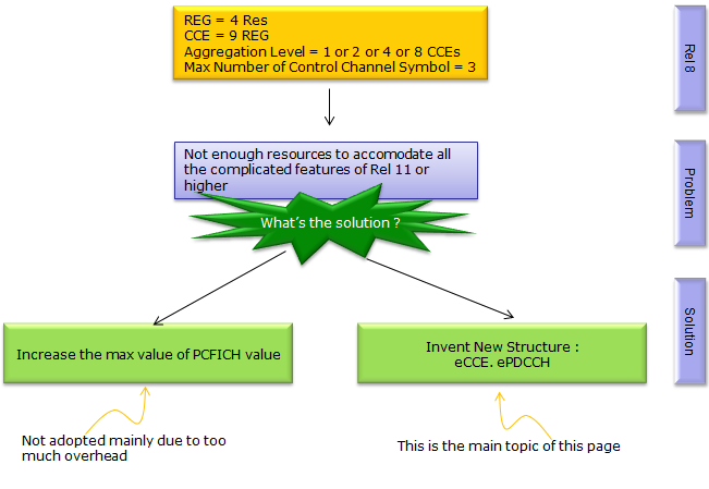
Figure 1. Two candidate answers to the same shortage. Raising the maximum PCFICH value was not adopted, because a taller control region costs every UE in the cell whether or not it is scheduled. Inventing a new structure, eCCE and ePDCCH, is what Rel-11 did instead.
By adopting this method, we may enjoy some additional advantage and followings are those advantage.
- decrease interference between control region from different cells
- increase the reliability of reception by applying BeamForming
How can we descrease interference between control region from different cells ? With ePDDCH, we can allocate control information for each user in such a way that ePDCCH for different users locate far away from each other to minimize the interference.
What does it mean by 'increase the reliability of reception by applying BeamForming' ? Since ePDCCH is in the area where PDSCH is located and each ePDCCH is UE specific, we may apply BeamForming technology and it would increase the reliability of signal reception.
Can we complete remove the CFI overhead ?
ePDCCH takes the UE specific assignments out of the control region, so the next question follows immediately. If those assignments have gone, can the control region go with them ? Let's look at what is still sitting in symbol 0 once ePDCCH has taken everything it is allowed to take.
If we can move the PDCCH data to PDSCH area, can we completely remove the overhead caused by the symbol 0 (or 1,2) ?
The answer is 'NO'. There are a couple of reason for this.
First, we still need the symbol 0 for PCFICH and PHICH. We don't have any new mechanism to move this part to other area.
Second, even with ePDCCH we cannot move the control information allocated in Common Search Space. So we still need to allocate a certain amount of the space in conventional way.
Third, ePDCCH only exists after RRC has configured it. A UE that is reading SIB1, decoding a random access response, or waking for paging has no EPDCCH-Config yet. It has to find those assignments in the legacy control region, and so does every other UE in the cell that is not yet in a configured state.
So ePDCCH moves the load rather than removing it. The control region can get smaller, because the UE specific traffic that used to fill it now has somewhere else to go. A cell with most of its scheduling on ePDCCH can therefore run at a lower CFI value. It still cannot run with no control region at all.
PCFICH and PHICH keep symbol 0 occupied : ePDCCH replaces neither of them, so the first symbol still carries something in every downlink subframe.The common search space stays on PDCCH : ePDCCH carries the UE specific search space only, so anything a UE must read before it has a dedicated configuration keeps using the legacy region.The saving is a lower CFI, not a missing control region : once the UE specific load moves out, the network can shrink the region to one or two symbols, and that is where the gain actually comes from.
Resource Allocation for ePDCCH
Following diagrams are from TDoc R-112517 Discussion on ePDCCH Design Issues (3GPP TSG-RAN1#66 meeting). This shows some possible idea of designing ePDCCH. It doesn't mean that all of these concept will be adopted by TS specification. But these can be a good reference for you to get general idea. Important thing to notice is that ePDCCH is allocated in those symbols allocated for PDSCH for conventional LTE.
At last, 3GPP Rel 11 adopted ePDCCH. It seems that 3GPP adopted the (a) Pure FDM (Refere to 36.211 36.211 6.2.4A/6.8A and)
R1-112517 Fig. 1 keeps a whole ePDCCH inside a set of resource blocks and gives each UE its own blocks. The yellow column on the left of each panel is the legacy PDCCH region, the blue blocks are eCCEs, and the green blocks are PDSCH. The three panels differ only in how much of the resource block pair the eCCEs are allowed to use.
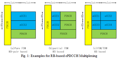
R1-112517 Fig. 1. Three ways to cut a resource block pair between ePDCCH and PDSCH. Panel (a) gives a whole PRB pair to one eCCE, which is simple to schedule but spends more resource elements than a control channel needs. Panel (b) uses only the first slot, which keeps the eCCE close to a legacy CCE in size and lets PDSCH decoding start in the second slot.
R1-112517 Fig. 2 takes the opposite approach. Several UEs share one set of resource blocks, and each UE's eREGs are interleaved across that set rather than kept together. The light blue cells belong to UE1 and the dark blue cells to UE2, so you can read the interleaving straight off the picture.
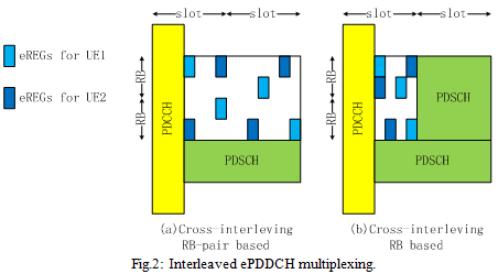
R1-112517 Fig. 2. Interleaved multiplexing spreads each UE's eREGs across the shared resource blocks, which buys frequency diversity when the network has no reliable subband feedback. The cost is that the shared region is closed to PDSCH, so any resource element the control channels leave unused is wasted.
Rel-11 did not pick one panel and discard the rest. 36.211 6.2.4A defines 16 eREGs per PRB pair, which is the eREG based granularity of the interleaved proposal, and 36.211 6.8A.1 then builds eCCEs out of those eREGs. On top of that structure it defines two transmission types. Localized transmission keeps the eREGs of one eCCE inside a single PRB, which is close in spirit to the first proposal. Distributed transmission spreads them across several PRBs, which is close to the second. The network chooses per ePDCCH set, so both ideas survived.
Both proposals reached the specification, under different names : what the contribution called non-interleaved and interleaved multiplexing became localized and distributed transmission in 36.211 6.8A.1.The choice trades diversity against beamforming : localized lets the network beamform towards one UE when it trusts the feedback it has, and distributed gives frequency diversity when it does not.ePDCCH always lives in the PDSCH symbols : whichever type is configured, the resource elements come from the region conventional LTE reserves for data, not from the control region.
eREG to RE Mapping
Before an eCCE can exist, the resource elements inside a PRB pair need labels. 36.211 does that with the eREG, which is a set of resource elements scattered through the pair rather than a contiguous block. The definition is one paragraph long and it is easy to read past, so let's take it slowly and then draw it.
36.211 6.2.4A describes as follows :
There are (1)16 EREGs, numbered from 0 to 15, per physical resource block pair. Number all resource elements, except resource elements carrying DM-RS for antenna ports p = {107,108,109,110} for normal cyclic prefix or p ={107,108} for extended cyclic prefix, in a physical resource-block pair cyclically from 0 to 15 in an increasing order of first frequency, then time. All resource elements with number i in that physical resource-block pair constitutes EREG number i .
If you translate this 3GPP statement into an illustration, it would look as follows. At the first glance, it would be hard to correlate this statement with the following illustration.. but read this statement several times and try to illustrate on your own. You may use following arrows and markers as a guideline to construct the eREG mapping. (I hope I am not confusing you rather than helping :)
i) Number all resource elements, except resource elements carrying DM-RS for antenna ports ==> Number from 0 through 15 and restart with 0 when it hits 15, but skip the resource element reserved for reference signal
ii) When you numbering, follow the path/direction marked by red arrows shown below.
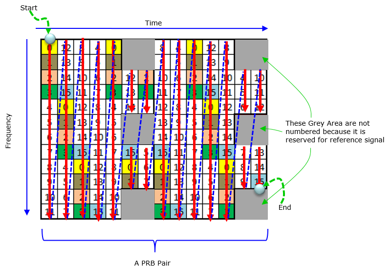
Figure 2. The numbering path behind the 36.211 definition. Counting runs down a column first and then moves one column to the right, which is what "first frequency, then time" means. The grey resource elements are skipped, because DM-RS already owns them.
The red arrows are the counting order : each one runs from the top of a column to the bottom, so the counter walks the frequency axis before it advances in time.The counter is cyclic, not per column : it runs 0 to 15 and then restarts at 0 wherever it happens to be, which is why a column rarely starts at 0.The grey cells never receive a number : those resource elements carry DM-RS for antenna ports 107 to 110, and the definition excludes them before the counting starts.An eREG is a number, not a shape : eREG 7 is simply every resource element the count labelled 7, wherever in the pair they happen to sit.
eREG to RE Mapping for Normal Subframe
There are two different ways of mapping eREG to RE. These mapping method are called Transmission type which is configured by IE transmissionType-r11. One is called 'localized' and the other is called 'distributed'.
Following is one example that shows the 'Localized' transmission type. Even though the RE location for each eREG is pretty much scrambled, you would recognize the pattern relatively easily and in this way you would notice that the REs in the same eREG would clustered in the same frequency. It implies that this kind of RE mapping would be vulnerable noise or fading. Due to this, 3GPP defines another mapping algorithm called 'distributed'. In distributed mapping, REs in an eREG is scattered in much random fashion so that they can have more resistance to noise and fading.
Following is an example of localized mapping (transmission type) for FDD and normal subframe of TDD.
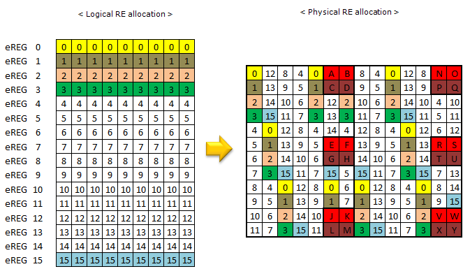
Figure 3. The same PRB pair seen logically and physically. On the left every eREG is a tidy row. On the right the same indices are scattered through the pair, so the colours are what let you follow one eREG between the two views.
The left panel is a bookkeeping view : it lists the resource elements belonging to each eREG in one row, which is convenient to read but is not how they sit on the air.The right panel is the real layout : each number is the eREG index of that resource element, and the numbers follow the counting path of Figure 2.The lettered cells carry DM-RS : they sit in the last two symbols of each slot, on the subcarriers reserved for antenna ports 107 to 110, and the eREG count skips every one of them.Localized means clustered, not contiguous : the eREGs of one eCCE stay inside one PRB, and that is what leaves the transmission exposed to a fade covering that PRB.
Following is an example of localized mapping (transmission type) special subframe config 1 and 6 of TDD.
eREG to RE Mapping for Special Subframe Config 1 and 6
A special subframe is shorter than a normal one, because DwPTS gives up symbols to the guard period and the uplink pilot. The eREG definition does not change, but there are fewer resource elements to hand out, so each eREG ends up with fewer of them. The picture below is the same pair of views as Figure 3, drawn for special subframe configurations 1 and 6.
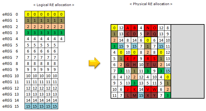
Figure 4. The same localized mapping in a special subframe. Each eREG row on the left is shorter than in Figure 3, and the grey block on the right is the part of the pair that DwPTS does not reach.
There are still 16 eREGs : 36.211 6.2.4A fixes the count per PRB pair, so a shorter subframe gives each eREG fewer resource elements rather than giving the pair fewer eREGs.Fewer resource elements per eREG means a weaker eCCE : 36.211 answers that by putting 8 eREGs into an eCCE instead of 4 for these configurations, which is the first table in the next section.Special subframe configurations 0 and 5 are absent on purpose : 36.213 9.1.4 says the UE does not monitor ePDCCH in them at all with normal downlink cyclic prefix, because DwPTS is too short to be worth the attempt.
How are eREG, eCCE and ePDCCH related ?
The last section stopped at the eREG, which is where the resource elements get their numbers. An ePDCCH is not built out of eREGs directly, though. Two grouping steps sit in between, and the numbers in them move with the subframe type and the cyclic prefix. Let's put the whole chain in one place, because the RRC fields further down only make sense once you can see it.
Figure 5. The two grouping steps between a resource element and a finished ePDCCH. The first count never changes, while the second and third both depend on the subframe, so a number quoted without its subframe type says very little.
The first step is the one the previous section covered, and it never changes. A PRB pair always holds 16 eREGs, whatever the subframe looks like.
The second step does change. 36.211 Table 6.8A.1-1 gives the number of eREGs in one eCCE, and it takes one of two values. Since the pair holds 16 eREGs either way, that number also fixes how many eCCEs one PRB pair can offer.
Cyclic prefix |
Subframe |
eREGs per eCCE |
eCCEs per PRB pair |
Normal |
Normal subframe |
4 |
4 |
Normal |
Special subframe, configuration 3, 4, 8 |
4 |
4 |
Normal |
Special subframe, configuration 1, 2, 6, 7, 9, 10 |
8 |
2 |
Extended |
Normal subframe |
8 |
2 |
Extended |
Special subframe, configuration 1, 2, 3, 5, 6 |
8 |
2 |
The first three columns are 36.211 Table 6.8A.1-1. The last column is 16 divided by the third, because 36.211 6.2.4A fixes the pair at 16 eREGs.
Read that last column as the capacity of one resource block pair. A normal subframe with normal cyclic prefix gives 4 eCCEs per pair, so a set of 2 PRB pairs offers 8 eCCEs in total. A special subframe in configuration 1 halves that, and the halving is the same arithmetic behind the shorter rows of Figure 4.
The third step is the aggregation level, and 36.211 calls the result an EPDCCH format. The number of eCCEs in one ePDCCH runs from 1 to 32, and which part of that range applies depends on whether 36.213 9.1.4 puts the subframe in case 1.
EPDCCH format |
Case A |
Case B |
||
Localized |
Distributed |
Localized |
Distributed |
|
0 | 2 | 2 | 1 | 1 |
1 | 4 | 4 | 2 | 2 |
2 | 8 | 8 | 4 | 4 |
3 | 16 | 16 | 8 | 8 |
4 | - | 32 | - | 16 |
36.211 Table 6.8A.1-2. The numbers are eCCEs per ePDCCH, and the dash means the format has no localized variant.
Case A applies when the conditions for case 1 in 36.213 9.1.4 hold, and case B applies otherwise. Case 1 needs a normal subframe with normal cyclic prefix, or one of special subframe configurations 3, 4 and 8. It also needs enough resource elements available for ePDCCH in a PRB pair, which is the ordinary situation on a wide carrier. So aggregation levels 2, 4, 8 and 16 are the common ones in practice, and 32 is there for distributed transmission when the channel is poor.
One more thing separates the two transmission types, and it sits at this level rather than at the eREG level. For localized transmission, the eREGs of one eCCE all come from a single PRB of the set, so the whole ePDCCH is concentrated where the network believes the UE receives best. For distributed transmission, the eREGs of one eCCE are taken from several PRBs of the set, so the ePDCCH is spread across the set.
The demodulation reference signal follows the same split. For localized transmission, 36.211 6.8A.5 picks a single antenna port out of 107 to 110. The choice comes from the lowest eCCE index of the candidate and from the C-RNTI, so the network can beamform that one port at the UE. Distributed transmission alternates the resource elements of an eREG between two antenna ports, starting at port 107. A null on one port therefore damages only part of the message.
Only the eREG count is constant : 16 per PRB pair always holds, while the eREGs per eCCE and the eCCEs per ePDCCH both follow the subframe.An eCCE is close to a legacy CCE in size : four eREGs of a normal subframe come to roughly the 36 resource elements of a Rel-8 CCE, which is why the aggregation levels look familiar.Aggregation level 32 exists only for distributed transmission : a UE that needs 32 eCCEs has a poor channel, and a poor channel is exactly when diversity helps more than beamforming does.The transmission type decides the antenna port rule : localized picks one port and beamforms it, and distributed alternates between two ports and takes diversity instead.
Where does the UE look for ePDCCH ?
Knowing how an ePDCCH is built still does not tell the UE where to try decoding one. On PDCCH the UE searches a common space and a UE specific space, and both are derived from the whole carrier. With ePDCCH the UE searches only the resource blocks the network chose for it, and the common part is gone.
36.213 9.1.4 gives the network one or two EPDCCH-PRB-sets per serving cell. Each set is a group of PRB pairs, and each set is configured on its own for either localized or distributed transmission. A network can therefore configure one localized set and one distributed set for the same UE, and let the scheduler pick whichever suits the channel.
Within a set, the eCCEs are numbered from 0 upwards, and the search space at each aggregation level is a list of candidates over those eCCEs. The number of candidates the UE has to try comes from the tables in 36.213 9.1.4, and it depends on how many sets are configured and which transmission types they use. The UE tries every candidate against every DCI format its transmission mode allows, which is the same blind decoding it already does on PDCCH.
Timing is configured separately. The field subframePatternConfig tells the UE which subframes carry a UE specific search space on ePDCCH. When that field is absent, the UE monitors every subframe except the ones the specification rules out. Those exclusions are worth knowing. When a UE never sees a grant in one particular subframe, one of them is usually the reason.
TDD special subframe configurations 0 and 5 : with normal downlink cyclic prefix the UE does not monitor ePDCCH in them, and with extended cyclic prefix the excluded configurations are 0, 4 and 7.Subframes carrying PMCH : the UE skips any subframe higher layers told it to decode PMCH in.Candidates overlapping PBCH or the synchronization signals : the UE is not expected to monitor a candidate whose eCCEs fall in a PRB pair that overlaps PBCH, PSS or SSS in the same subframe.BL and CE UEs : they do not monitor ePDCCH at all, because 36.213 9.1.5 gives them MPDCCH instead.
One consequence deserves stating on its own, because it comes back in the RRC section. An ePDCCH carries the UE specific search space and nothing else. There is no common search space on ePDCCH, so SIB scheduling, paging and random access responses stay on PDCCH for the life of the cell. That is the same limit the CFI section reached from the other direction.
Two sets are the maximum, not the default : 36.331 defines maxEPDCCH-Set-r11 as 2, and a network that configures a single set is entirely normal.Each set carries its own transmission type : localized and distributed are per set, so a UE can monitor one of each and leave the choice to the scheduler.The blind decoding load moved rather than disappeared : the candidate count per aggregation level is still fixed by the specification, and the UE still tries all of them.
RRC Aspect of eCCE/ePDCCH
Following is the overall RRC message structure to configure ePDCCH. Some of these are straightforward and some of them would need a lot of effort to completely understand the concept down to the physical layer. I will keep updating as I get more understanding on details.
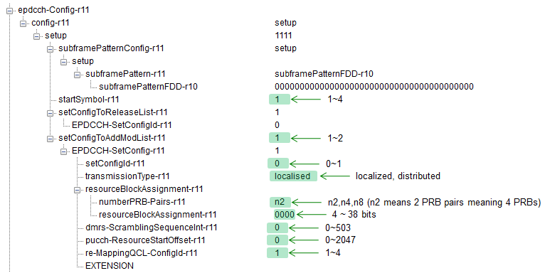
Figure 6. One decoded EPDCCH-Config, with the value ranges written beside the fields that have them. This is a capture from a decoder rather than specification text, so read it as one network's choice and not as the only legal one.
config-r11 is a setup or release choice : the whole ePDCCH configuration arrives on one branch, so releasing it removes every set at once.setConfigToAddModList-r11 holds the sets : this capture has one entry, and the annotation beside it records that the list can hold 1 or 2.transmissionType-r11 is per set : this capture chose localised, and that spelling with an s is what the 36.331 enumeration uses.resourceBlockAssignment-r11 is a pair of fields : numberPRB-Pairs-r11 says how many PRB pairs the set has, and the bit string that follows says which ones.
ASN.1 Definition of EPDCCH-Config
Figure 6 is one decoded instance, and a decode only shows the branches that were actually populated. The definition below shows every branch, including the ones this capture left empty and the extension groups added after Rel-11. Keep the two side by side, because the field descriptions that follow name fields which only appear in the definition.
Following is based on
EPDCCH-Config-r11 ::=           SEQUENCE {
    config-r11                      CHOICE {
        release                         NULL,
        setup                           SEQUENCE {
            subframePatternConfig-r11       CHOICE {
                release                         NULL,
                setup                           SEQUENCE {
                    subframePattern-r11             MeasSubframePattern-r10
                }
            }                                                       OPTIONAL,   -- Need ON
            startSymbol-r11                 INTEGER (1..4)          OPTIONAL,   -- Need OP
            setConfigToReleaseList-r11      EPDCCH-SetConfigToReleaseList-r11
                                                                    OPTIONAL,   -- Need ON
            setConfigToAddModList-r11       EPDCCH-SetConfigToAddModList-r11
                                                                    OPTIONAL    -- Need ON
        }
    }
}

EPDCCH-SetConfigToAddModList-r11 ::=    SEQUENCE (SIZE(1..maxEPDCCH-Set-r11)) OF EPDCCH-SetConfig-r11

EPDCCH-SetConfigToReleaseList-r11 ::=   SEQUENCE (SIZE(1..maxEPDCCH-Set-r11)) OF EPDCCH-SetConfigId-r11

EPDCCH-SetConfig-r11 ::=        SEQUENCE {
    setConfigId-r11                 EPDCCH-SetConfigId-r11,
    transmissionType-r11            ENUMERATED {localised, distributed},
    resourceBlockAssignment-r11     SEQUENCE {
        numberPRB-Pairs-r11             ENUMERATED {n2, n4, n8},
        resourceBlockAssignment-r11     BIT STRING (SIZE(4..38))
    },
    dmrs-ScramblingSequenceInt-r11  INTEGER (0..503),
    pucch-ResourceStartOffset-r11   INTEGER (0..2047),
    re-MappingQCL-ConfigId-r11      PDSCH-RE-MappingQCL-ConfigId-r11
                                                                    OPTIONAL,   -- Need OR
    ...,
    [[  csi-RS-ConfigZPId2-r12          CHOICE {
            release                         NULL,
            setup                           CSI-RS-ConfigZPId-r11
        }                                                           OPTIONAL    -- Need ON
    ]],
    [[  numberPRB-Pairs-v1310           CHOICE {
            release                         NULL,
            setup                           ENUMERATED {n6}
        }                                                           OPTIONAL,   -- Need ON
        mpdcch-config-r13               CHOICE {
            release                         NULL,
            setup                           SEQUENCE {
                csi-NumRepetitionCE-r13         ENUMERATED {sf1, sf2, sf4, sf8, sf16, sf32},
                mpdcch-pdsch-HoppingConfig-r13  ENUMERATED {on,off},
                mpdcch-StartSF-UESS-r13         CHOICE {
                    fdd-r13                         ENUMERATED {v1, v1dot5, v2, v2dot5, v4,
                                                                v5, v8, v10},
                    tdd-r13                         ENUMERATED {v1, v2, v4, v5, v8, v10,
                                                                v20, spare1}
                },
                mpdcch-NumRepetition-r13        ENUMERATED {r1, r2, r4, r8, r16,
                                                            r32, r64, r128, r256},
                mpdcch-Narrowband-r13           INTEGER (1.. maxAvailNarrowBands-r13)
            }
        }                                                           OPTIONAL    -- Need ON
    ]]
}

EPDCCH-SetConfigId-r11 ::=      INTEGER (0..1)
Three fields in that definition are newer than the diagram above it. The Rel-12 addition is csi-RS-ConfigZPId2-r12, which adds a second zero power CSI-RS configuration for rate matching. E-UTRAN configures that one only for transmission mode 10. Rel-13 brought the other two. One of them, numberPRB-Pairs-v1310, adds the value n6. The other, mpdcch-config-r13, carries the repetition and narrowband parameters MPDCCH needs. Both serve BL UEs and UEs in coverage enhancement, so a normal UE never sees either of them.
Two constants are worth carrying away from the listing. 36.331 defines maxEPDCCH-Set-r11 as 2, and that is the limit behind the one or two sets of 36.213 9.1.4. It also defines EPDCCH-SetConfigId-r11 as INTEGER (0..1), so the two sets are identified as 0 and 1 and nothing else.
EPDCCH-SetConfig : Provides EPDCCH configuration set. See TS 36.213 - 9.1.4. E-UTRAN configures at least one EPDCCHSetConfig when EPDCCH-Config is configured.
setConfigId : Indicates the identity of the EPDCCH configuration set.
subframePatternConfig : Configures the subframes which the UE shall monitor the UE-specific search space on EPDCCH, except for predefined rules in TS 36.213 9.1.4. If the field is not configured when EPDCCH is configured, the UE shall monitor the UE-specific search space on EPDCCH in all subframes except for pre-defined rules in TS 36.213-9.1.4.
transmissionType : Indicates whether distributed or localized EPDCCH transmission mode is used as defined in TS 36.211-6.8A.1.
EPDCCH Starting Position : 36.213 9.1.4.1
A UE reading PDCCH learns from PCFICH where the control region ends, and then knows where PDSCH begins. An ePDCCH needs the same answer, but the UE cannot always wait for PCFICH, and under transmission mode 10 it is told not to use PCFICH at all. 36.213 9.1.4.1 sets out which of the three sources applies in which case.
startSymbol : Indicates the OFDM starting symbol for any EPDCCH and PDSCH scheduled by EPDCCH on the same cell, see TS 36.213-9.1.4.1. If not present, the UE shall release the configuration and shall derive the starting OFDM symbol of EPDCCH and PDSCH scheduled by EPDCCH from PCFICH. Values 1, 2, and 3 are applicable for dl-Bandwidth greater than 10 resource blocks. Values 2, 3, and 4 are applicable otherwise. E-UTRAN does not configure the field
for UEs configured with tm10.
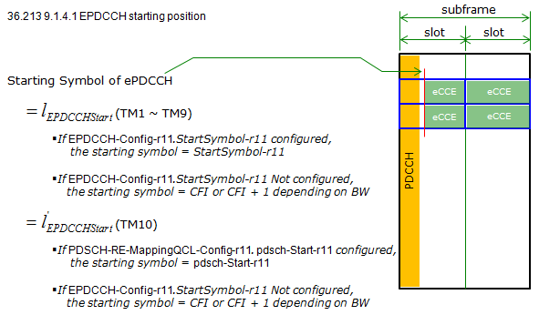
Figure 7. Where the ePDCCH starting symbol comes from. The transmission mode decides which RRC field is consulted first, and the CFI value is only the fallback when neither field is configured.
Transmission modes 1 to 9 read StartSymbol-r11 : when EPDCCH-Config carries that field, its value is the starting symbol and PCFICH is not consulted.Transmission mode 10 reads pdsch-Start-r11 instead : the starting symbol comes from the PDSCH-RE-MappingQCL-Config the set points at, which is why E-UTRAN does not configure startSymbol for a tm10 UE.The fallback is CFI, or CFI plus one : with neither field configured the UE derives the symbol from PCFICH, and it adds one on a narrow carrier where the control region already needs the extra symbol.The value range follows the bandwidth : values 1, 2 and 3 apply above 10 resource blocks, and values 2, 3 and 4 apply otherwise, which is the same asymmetry the CFI fallback shows.
PRB-pair indication for EPDCCH : 36.213 9.1.4.4
A set has to say which PRB pairs belong to it, and a plain bitmap would be expensive on a wide carrier. 36.213 9.1.4.4 uses a combinatorial index instead. One integer names one particular combination of PRB pairs out of all the combinations of that size. Two RRC fields carry it, and the second one only makes sense once you know the first.
numberPRB-Pairs : Indicates the number of physical resource-block pairs used for the EPDCCH set. Value n2 corresponds to 2 physical resource-block pairs; n4 corresponds to 4 physical resource-block pairs and so on. Value n8 is not supported if dl-Bandwidth is set to 6 resource blocks.
resourceBlockAssignment : Indicates the index to a specific combination of physical resource-block pair for EPDCCH set. See TS 36.213 - 9.1.4.4. The size of resourceBlockAssignment is specified in TS 36.213 9.1.4.4 and based on numberPRB-Pairs and the signalled value of dl-Bandwidth.
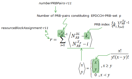
Figure 8. The combinatorial index of 36.213 9.1.4.4, with each symbol traced back to the RRC field that supplies it. The field numberPRB-Pairs fixes how many PRB pairs are being chosen, and resourceBlockAssignment is the index r that says which combination was chosen.
The index is a label, not a bitmap : r counts combinations, so every legal set of PRB pairs of the configured size gets exactly one value and no value is wasted.numberPRB-Pairs has to come first : it fixes the size of the combination, and that size is what decides how many combinations exist and how many bits r needs.That is why the bit string runs from 4 to 38 bits : the width follows from the configured set size and the downlink bandwidth. 36.331 says as much when it points at 36.213 9.1.4.4 for the size.The extended binomial coefficient handles the edge case : the definition in the lower right returns zero when x is smaller than y, so the sum stays well defined at both ends of the range.
Reference
The clauses this page is built on, and the contribution the two multiplexing figures come from.
- TS 36.211 v19.3.0 : Physical channels and modulation - clause 6.2.4A Enhanced Resource-Element Groups, and clause 6.8A Enhanced physical downlink control channel
- TS 36.213 v19.4.0 : Physical layer procedures - clause 9.1.4 EPDCCH assignment procedure, with 9.1.4.1 and 9.1.4.4
- TS 36.331 v19.3.0 : Radio Resource Control protocol specification - the EPDCCH-Config information element and its field descriptions
- R1-112517 : Samsung - Discussion on ePDCCH Design Issues, 3GPP TSG-RAN1#66, Athens, August 2011