Relay Node
One of the biggest problem in LTE would be that the performance at cell edge would not be as good as those in CDMA/WCDMA. So understandably, one of the biggest feature of LTE advanced would be to come out with a wise compensation measure. On top of it, this compensation measure should be very economic.
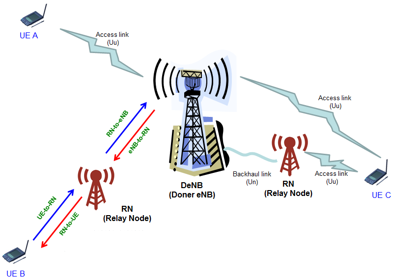
One of the most popular idea (or real implemetation) for this would be to add various relay node (RN) as illustrated below.
Conceptually Relay Node can be implemented in any layer (e.g,RF/L1, L2, L3) as described in DoCoMo Technology Report vol 12-2, but as 3GPP specification gets established as in 36.216, it seems the implementation goes towards L1 and low L2. It means it would do some baseband processing and low MAC scheduling as well.
Physical Layer aspect
As you see in the illustration above, Relay Node has two radio access interfaces. One is for radio access with UE and the other is for radio access for eNB. According to 36.216, each path is labeled with its own name as shown in the picture (UE-to-RN, RN-to-eNB, eNB-to-RN, RN-to-UE).
< Can a Relay Network communicate with eNB at any subframe ? >
This was the first question that popped up in my mind and the answer from 36.216 is 'No, they need to communicate only at specific subframe.
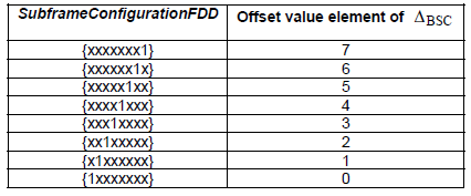
In case of FDD, this communication can happen only at the subframe that satisfy the following condition.
![]()
36.216 Table 5.2-1 : Downlink subframe configuration for eNB-to-RN transmission
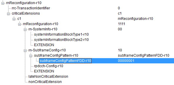
Which of the configuration will be used is determined by RRC message (rnReconfiguration) as shown below.
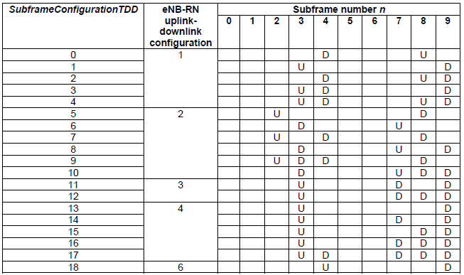
In case of TDD, this communication can happen only at the subframe
36.216 Table 5.2-2 : Supported Configurations for eNB-RN transmission
Which of the configuration will be used is determined by RRC message (rnReconfiguration) as shown below.

< Can a Relay Network communicate with eNB at any OFDMA Symbol ? >
The answer from 36.216 is 'No' as well in this case. The usuable symbol differs between the first and second symbol as well. This symbol allocation is also defined in 36.216 as shown below.
36.216 Table 5.4-1 : OFDM Symbols for eNB-to-RN transmission in the first slot
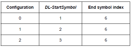
36.216 Table 5.4-2 : OFDM Symbols for eNB-to-RN transmission in the second slot
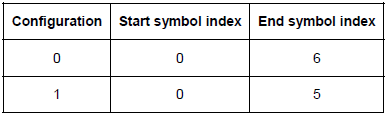
Which Symbols can be used is determined by RRC message as shown below.
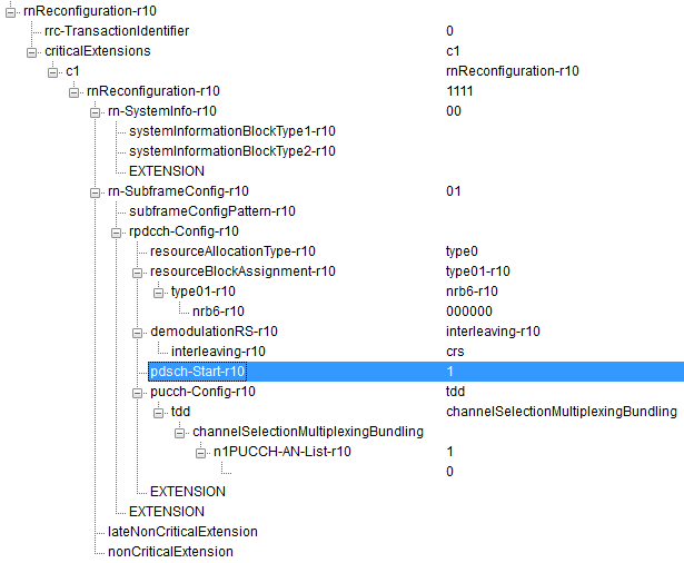
< Does eNB/RN use the same type of DCI and Control Channel as in eNB/UE communication >
DCI would be the same type as in eNB/UE, but the control channel that carries the DCI is different. eNB-to-RN transmission we use a special control channel called R-PDCCH.
There are differences between R-PDCCH and conventional PDCCH as well. Whereas PDCCH is carried by the special control symbols (symbo 0-2 depending on CFI setting), R-PDCCH is carried outside of the conventional PDCCH region. More specifically, R-PDCCH is carried in Configuration 2 in 36.216 Table 5.4-1 or Configuration 0 or 1 in 36.216 Table 5.4-2. If R-PDCCH is carried by the first slot, PDSCH cannot be allocated in that slot.
For further details, refer to 5.6 of 36.216
< Does eNB use the same downlink reference signal as in eNB-to-UE Communication >
The answer is Yes with a little bit of exception as follows :
- The reference signal sequence of antenna port 7,8,9,10 shall only be mapped to resource elements in the first slot of a PRB pair if the configuration 1 in Table 5.4-2 is used.
- Antenna ports 11 to 14 shall not be used for eNB-to-RN transmission