|
Embedded System - Intel Quark |
||
|
D2000 Pin Map
One of things that I think need to be improved a lot about this board is documentation. I liked 'Getting Started' part is pretty well organized, but getting just a little bit deeper it is difficult to find necessary document and even when found it was not easy to make sense out of it. In many cases, same things are found in many different document but described in a little bit different way which confuses me. Also things presented in the document does not clearly matches the constants (definitions) found in sample program. At least to me, D2000 documentation was not as clear as Arduino document or Beaglebone document. I guess (hope) this would improve as time goes on. This is just my personal impression and you may not feel this is any problem though.
Whenever I start playing with any new embedded board, one of the first thing I do is to find out the documents about pin mapping and pin configuration documents and write my own notes.
Regarding Quark pin mapping / configuration, I found descriptions on Pin mapping and configuration from following documents. I would not just copy these information and past it here.. you can google those information by the title or file names listed below. The important thing is how to interpret the document. What I am trying to do is to show how to interpret the infromation in the document and get some practical information that can directly applied when you are programming the board. I will try to show you by specific examples.
Example : UART TXD
In this example, I will show you on where to find information on UART TXD pin as shown below.
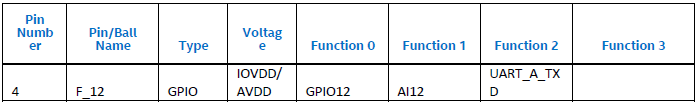
If the first document you opened up is following table, you are lucky. I think this is the best organized table which would give you most of the information except Arduino breakout information.
< Table 4. Pin Multiplexing in Intel� Quark� Microcontroller D2000 >
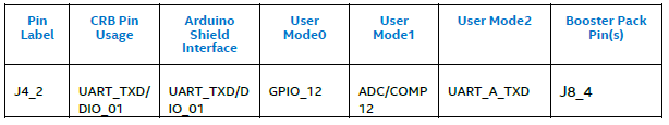
Then you can find the same information from another table as below. In this table, you can find 'Arduino Shield Interface'. But you would notice that the term 'Function' is changed to 'User Mode'. Are these same ? I guess so.
< Table 5. Pin Mapping in Intel� Quark� Microcontroller Developer Kit D2000 >
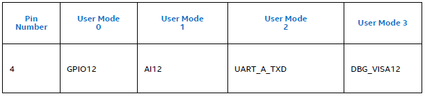
You can find similar information from different tables as shown below. If you have already fount the tables shown above you may simply ignore following two tables, but if you only get these tables only you might be struggling because there is no board specific information.
< Table 2. Pin Multiplexing in Intel� Quark� Microcontroller D2000 - Pin Connectivity >
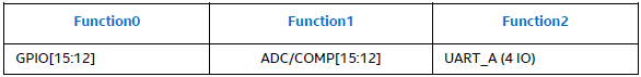
< Table 3. Multiplexed Functions in Intel� Quark� Microcontroller D2000 >
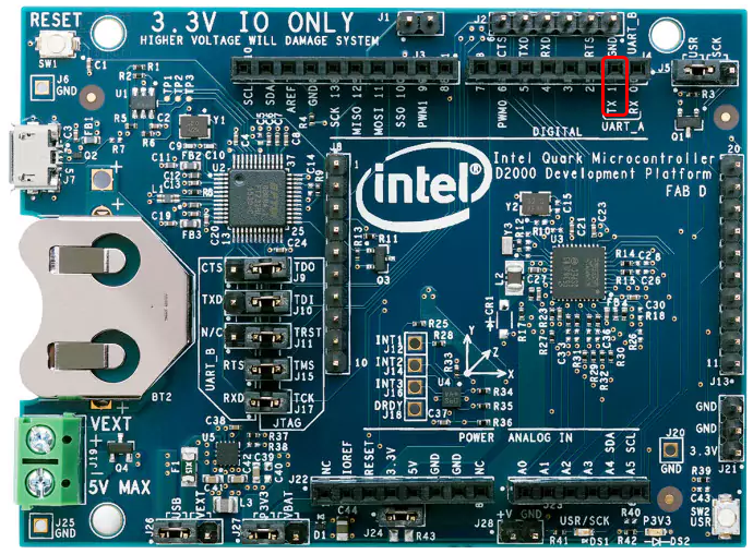
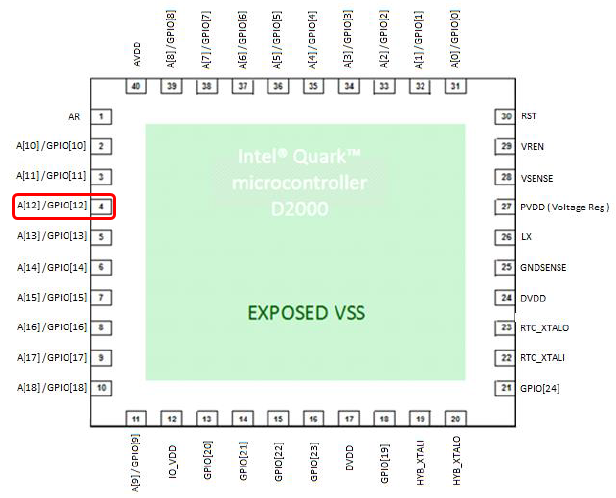
This may not be the mandatory information, but I would recommend you to trace back to the chipset pin number as shown below. How do I know the pin marked in red is the one for UARTA TXD ? In this case, you can correlate the tables shown above in a few different way. You may use the pin number '4' or one of the user mode 'GPIO 12' as a reference.
< Figure 2. Package Diagram QFN 40 pin (0.5mm pitch) in Intel� Quark� Microcontroller D2000 >
Now with all of these information, you should be able to configure the pin as you like. In the table shown above, you would notice that this pin can be used in three different way (User Mode 0,1,2 or Function 0,1,2) depending on how you configure it.
Let's get back to the following table.
< Table 4. Pin Multiplexing in Intel� Quark� Microcontroller D2000 >
This table says :
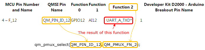
How to configure the pin in programming ? In C programming, you can do the configuration as follows by using qm_pmux_select().
qm_pmux_select(QM_PIN_ID_12, QM_PMUX_FN_2);
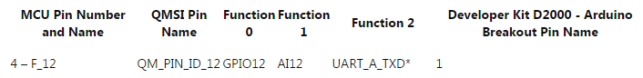
Here you see some other parameters that were not found in the table shown above : QM_PIN_ID_12, QM_PMUX_FN_2. To find this, you need another table as shown below :
I found this table from Using UARTs on Intel� Quark� Microcontroller D2000 (CODE PROJECT) . But this table is not from the official document that comes with D2000 and this article provide the table only for UART. For programming in C, we would need this kind of table for all the pins for D2000 board. Once you get a table like this, you can configure each pin in C programming as follows.
[1]
|
||