Frame Structure : Downlink
Even though the name still remain as 'LTE-something", LTE-NB is pretty new design from the very bottom (Physical Layer). The biggest difference of any new wireless communication technology starts from physical layer frame structure. LTE-NB frame structure can be summarized as follows.
Since LTE-NB is considered as a LTE family, it has some commonalities with the legacy LTE as follows :
- The length of a subframe is 1 ms
- One Radio Frame is made up of 10 subframes
- Number of Subcarriers whithin a RB is 12
However, there are some characteristics of LTE-NB which are different from the legacy LTE :
- System Bandwidth is always 180 Khz
- The number of RB within a system bandwidh is always 1
- NPSS and NSSS are located in different subframes (whereas PSS, SSS in legacy LTE are located in same subframes).
- NPSS is transmitted in every radio frame but NSSS is transmitted in every two radio frames (in even frame) (whereas both PSS, SSS are transmitted in every radio frame)
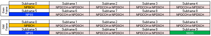
< Physical Channel Allocations within a Radio Frame >
Now let's look into the details (RE map) of each subframe. As mentioned in LTE-NB Operation Mode page, there are three different Operation Mode (Deployment Mode) namely In-Band, Guardband, Standalone mode. The detailed RE mapping varies a little bit depending on Operation Mode as showin in following sections.
Frame Structure for In-Band Deplyment (Operation Mode)
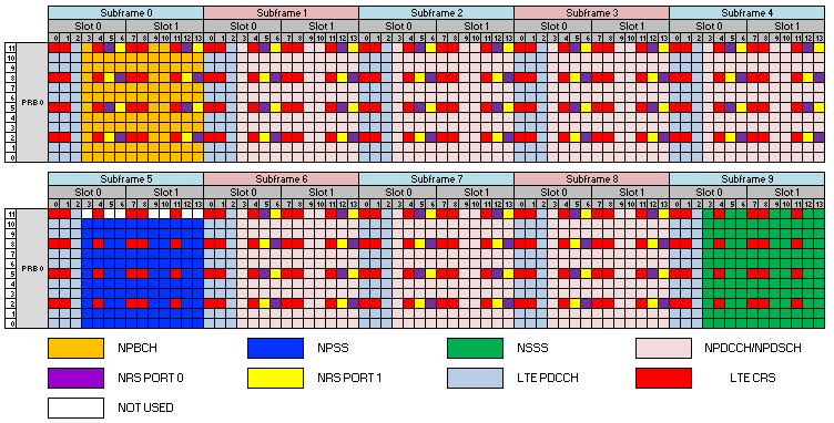
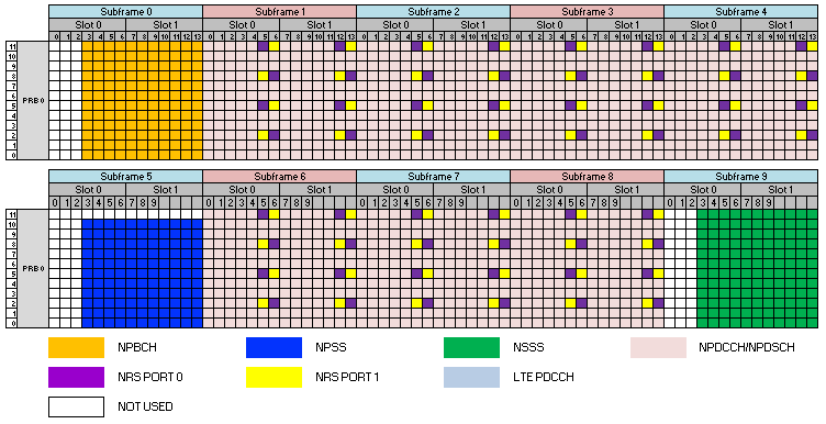
Following subframe structure shows the case in In-Band operation mode. Some of highlights of this frame structure can be summarized as follows (Think of your own interpretation before reading the following description) :
- LTE (Legacy LTE) Reference Signal still exists (This is because LTE Reference Signal is spread across the full systemband. LTE-NB deployment within the system bandwidth should not block the legacy LTE reference signal)
- The first thre symbols of each subframe is always reserved for legacy LTE. They are not used for LTE-NB (This is because LTE Control Signal region is spread across the full systemband. LTE-NB deployment within the system bandwidth should not block the legacy LTE Control Signal region)
- NPBCH occupies a whole subframe except the first three symbols at subframe 0 (See NPBCH Page for further details)
- NPSS occupies a whole subframe except the first three symbols and the last subcarrier at subframe 5 of every radio frame (See NPSS Page for further details)
- NSSS occupies a whole subframe except the first three symbols and the last subcarrier at subframe 9 of every even radio frame (See NSSS Page for further details)
- LTE-NB Reference Signal is located in symbol 5,6 and 12,13 of every subframe except the subframe for NPSS, NSSS subframe.
Following illustration is kindly provided by Damodar D from Lekha Wireless who is working on LTE-NB impementation and has been throughly reviewed by Samuele Riva from PRISMA Telecom Testing and some other additional correction by Venkatesh Yadav. Many of my initial mistake were corrected by his effort.
When you allocate the resources for Reference Signal, NPBCH, NPSS,NSSS, you should consider following factors since LTE-NB deployment should not interfere with the existing Legacy LTE resource allocation.
NPBCH : Based on 36.211-10.2.4.4
For the purpose of the mapping, the UE shall assume cell-specific reference signals for antenna ports 0-3 and narrowband reference signals for antenna ports 0 and 1 being present irrespective of the actual configuration
NPSS : Based on 36.211-10.2.7.1.2.
For resource elements (k,l) overlapping with resource elements where cell-specific reference signals according to clause 6.10 (Legacy LTE CRS) are transmitted, the corresponding sequence element d(n) is not used for the NPSS but counted in the mapping process.
NSSS : Based on 36.211-10.2.7.2.2.
For resource elements (k,l) overlapping with resource elements where cell-specific reference signals according to clause 6.10 (Legacy LTE CRS) are transmitted, the corresponding sequence element d(n) is not used for the NSSS but counted in the mapping process.
< LTE-NB Frame Structure for In-Band Deployment (Even Radio Frame) >
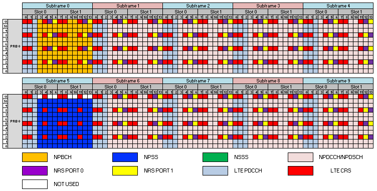
< LTE-NB Frame Structure for In-Band Deployment (Odd Radio Frame) >
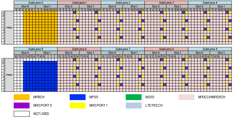
Frame Structure for Guarband and StandAlone Deplyment (Operation Mode)
Following subframe structure shows the case in Guardband and Standalone operation mode. Some of highlights of this frame structure can be summarized as follows (Think of your own interpretation before reading the following description) :
- NPBCH occupies a whole subframe except the first three symbols at subframe 0 (See NPBCH Page for further details)
- NPSS occupies a whole subframe except the first three symbols and the last subcarrier at subframe 4 of every radio frame (See NPSS Page for further details)
- NSSS occupies a whole subframe except the first three symbols and the last subcarrier at subframe 9 of every even radio frame (See NSSS Page for further details)
- LTE-NB Reference Signal is located in symbol 5,6 and 12,13 of every subframe except the subframe for NPSS, NSSS subframe.
Following illustration is kindly provided by Damodar D from Lekha Wireless who is working on LTE-NB impementation and has been throughly reviewed by Samuele Riva from PRISMA Telecom Testing. Many of my initial mistake were corrected by his effort.
< LTE-NB Frame Structure for Guardband/Standalone Deployment (Even Radio Frame) >
< LTE-NB Frame Structure for Guardband/Standalone Deployment (Odd Radio Frame) >