How do two NG-RAN nodes coordinate when a UE moves between them or uses resources from both? Xn gives the nodes a logical link for signalling and user plane transfer. It connects RAN nodes to each other, while NG connects a RAN node to the 5G Core.
- Where Xn Sits
- Which Nodes Use Xn ?
- What Xn Carries
- Xn Protocol Stacks
- Xn Signaling Messages
- How Handover Works ?
- How NSA Establishment Works ?
- How NSA with NR Carrier Aggregation Works ?
- Other Xn Procedures
- When Does Xn Setup Happen ?
- Xn-C ASN
- Reference
Where Xn Sits
Start with the red links in Figure 1. The LTE side labels the links between eNBs X2. The 5G/NR side labels the links between gNBs Xn. The green links serve a different purpose: they connect each base station toward its core network.
Figure 1 puts these two relationships next to each other. On the NR side, the green NG-C and NG-U paths lead toward the AMF and UPF, while the red Xn paths join neighbouring gNBs. The drawing shows gNB-to-gNB connections, but the Xn specification defines the interface between NG-RAN nodes more generally.
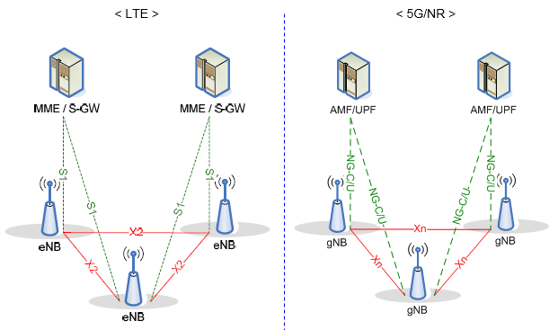
Figure 1. Xn joins neighbouring NG-RAN nodes; NG-C and NG-U connect them toward the 5G Core.
The red Xn link represents a logical point-to-point interface. It does not require a dedicated physical cable between the two nodes. Their transport network may carry the traffic through intermediate equipment, as long as the nodes can reach each other.
This distinction matters when reading an architecture drawing or a trace. An Xn message has another NG-RAN node as its peer. An NG message has a core-network function as its peer. A handover may involve both interfaces, but the labels tell you which part of the exchange you are looking at.
The link colour does not identify the message format. First locate both endpoints in the trace: two NG-RAN nodes indicate Xn, while an NG-RAN node and the AMF indicate NG-C. Then check whether the exchange is control signalling or forwarded user data. That second check distinguishes Xn-C from Xn-U on the same peer relationship.
Figure 1 separates LTE/EPC from NR/5GC for clarity. It does not draw an ng-eNB and gNB serving one UE together. That mixed radio arrangement is why the NSA addition section distinguishes X2 from Xn.
A UE may use several carriers without creating another Xn peer. If its secondary gNB adds an NR SCell, that carrier remains inside the gNB's secondary cell group. The peer relationship is still between the master and secondary nodes, not between individual component carriers. The carrier-aggregation section below separates those two levels of the architecture.
In a trace, this means a new SCell may appear in UE-facing NR signalling while the same two nodes remain at the Xn endpoints. The carrier change does not create an extra logical Xn interface.
Xn is between NG-RAN nodes. The red links on the NR side show this relationship.NG is toward the 5G Core. The green NG-C and NG-U links show that separate relationship.
Which Nodes Use Xn ?
Figure 1 draws gNBs at both ends of Xn, which is the easiest case to picture. But what counts as a peer in a deployed NG-RAN? The interface is defined between NG-RAN nodes, so the answer is wider than the three gNB icons in the drawing.
A gNB provides NR radio access. An ng-eNB provides E-UTRA radio access while connecting to the 5G Core. Both can be NG-RAN nodes. This is why a drawing of Xn between gNBs is an example of the architecture rather than the complete list of possible peers. Check whether an LTE-looking node is an ng-eNB connected to 5GC before calling its inter-node link X2.
The common NR NSA case is EN-DC with EPC. Here an LTE eNB is the master node and an en-gNB is the secondary node. The eNB starts SgNB Addition over X2-C, and the en-gNB acknowledges it. The eNB then sends the resulting NR configuration to the UE in an LTE RRCConnectionReconfiguration. User plane transfer between the nodes uses X2-U when it is needed.
The answer changes for dual connectivity with the 5G Core. NGEN-DC uses an ng-eNB as master and a gNB as secondary; NE-DC reverses those radio roles. NR-DC can use two gNBs. These 5GC-based arrangements use Xn-C between master and secondary nodes, and Xn-U for inter-node user plane transfer. Check the core network and node types before choosing X2 or Xn.
The internal split of a gNB is another source of confusion. A gNB can contain a central unit, gNB-CU, and one or more distributed units, gNB-DUs. The interface between its CU and DUs is F1. For this split gNB, Xn-C terminates at the gNB-CU. A peer gNB still sees one gNB across Xn rather than separate DUs as Xn peers.
The words source and target describe temporary roles in a mobility procedure. The source serves the UE before handover; the target prepares resources for the UE to arrive. In dual connectivity, the roles are different: a master node coordinates with a secondary node that supplies additional resources. Neither pair of names identifies a new physical interface. They describe what the two NG-RAN nodes are doing over Xn.
Peer nodes are NG-RAN nodes. The gNB-to-gNB drawing is one common case.F1 stays inside a split gNB. Xn-C joins that gNB to another NG-RAN node through its gNB-CU.Roles depend on the procedure. Source and target belong to handover; master and secondary belong to dual connectivity.EN-DC addition uses X2-C. Xn-C applies to dual connectivity between NG-RAN nodes with 5GC.
What Xn Carries
Once the nodes have an Xn link, what do they send over it? Separate the control plane from the user plane first. Xn-C carries coordination messages. Xn-U carries user plane data between the nodes when a procedure needs that transfer.
On Xn-C, the application protocol is XnAP over SCTP/IP. The nodes use it to set up their Xn relationship, update configuration data and report errors. They also use Xn-C for mobility and dual-connectivity procedures. For example, a source node can send handover preparation information to a target node before the UE moves.
Handover preparation is only part of the exchange. The source and target can establish forwarding transport bearers, so data can reach the target during the move. Xn-C controls that arrangement. Xn-U carries the forwarded user plane packets over GTP-U/UDP/IP. The Xn-U service does not guarantee delivery, so do not read the red line in Figure 1 as a lossless data path.
Xn also supports dual connectivity. In that case, a secondary NG-RAN node can provide additional radio resources while the nodes coordinate over Xn. The same interface therefore supports both a change of serving node and cooperation between nodes that serve a UE at the same time. The procedures and the traffic differ, even though the peer nodes are connected through Xn in both cases.
An Xn-C trace names a procedure and exposes its XnAP information elements. The IE list may contain node identities, UE identifiers, admitted PDU sessions, a transparent RRC container, or PDCP status, depending on the message. Xn-U packets are different: they carry user-plane data in GTP-U tunnels. The ASN.1 examples later in this note show why one generic description of an Xn-C payload is not enough.
Not every radio change causes a new XnAP exchange. Once dual connectivity is established, a secondary node may configure an NR SCell directly over NR SRB3 when the master does not need to coordinate that change. If the master relays the configuration, XnAP carries the inter-node modification while RRC carries the UE-facing configuration. An NR SCell Activation MAC CE then travels over the radio interface, not over Xn-C or Xn-U.
This distinction helps when a trace shows more downlink traffic but no new XnAP message. The secondary node may have activated an already configured NR carrier. Conversely, a successful XnAP modification only proves that the nodes coordinated the change; it does not by itself prove that the UE activated or used the new carrier.
Xn-C coordinates the nodes. XnAP carries setup, mobility and dual-connectivity signalling over SCTP/IP.Xn-U transfers data. GTP-U over UDP/IP carries user plane packets for forwarding or dual connectivity.
Xn Protocol Stacks
What should you look for when an Xn packet appears in a trace? The two planes share IP transport, but the layers above IP tell you whether the packet is signalling or user plane traffic. This distinction is more reliable than the packet's destination alone.
For Xn-C, the stack is XnAP over SCTP over IP. XnAP defines the messages and procedures exchanged by the NG-RAN nodes. SCTP provides reliable delivery of these signalling messages. IP carries them across the transport network. An Xn Setup exchange or a Handover Request belongs to this stack, so start at XnAP when interpreting its information elements.
For Xn-U, the stack is user plane PDUs over GTP-U, UDP and IP. GTP-U carries data between tunnel endpoints on the two NG-RAN nodes. Depending on the procedure, the carried data can be PDCP PDUs, PDCP SDUs or SDAP SDUs. Xn-U itself provides non-guaranteed delivery. Its flow-control information lets a receiving node report how the transferred data flow is progressing.
Figure 2 puts the two stacks side by side. Read each column from top to bottom. Both use IP and the lower transport layers, but Xn-C places SCTP under XnAP while Xn-U places GTP-U and UDP under the user plane PDUs.
Figure 2. Xn-C carries XnAP signalling over SCTP, while Xn-U carries user plane PDUs over GTP-U and UDP.
- The coloured upper layers differ between the two planes. XnAP defines the control messages; GTP-U carries user plane packets.
- The grey IP, data link and physical layers are common to both stacks. The diagram does not imply that they use separate physical networks.
The transport distinction also explains why setup and forwarding are separate observations. Xn-C may establish forwarding resources and exchange tunnel information. Only then can Xn-U packets use the corresponding tunnel. A trace with successful XnAP preparation but no GTP-U packets does not by itself prove that forwarding failed; the procedure may not need forwarding for that bearer.
NR RRC and MAC messages sent directly between a gNB and UE use Uu, so they do not belong in either Xn stack. This matters during carrier aggregation: an NR SCell can be configured over SRB3 and activated by a MAC CE without putting those messages on Xn-C. If the master relays the RRC configuration, XnAP carries only the inter-node part.
Control plane: XnAP / SCTP / IP carries inter-node signalling.User plane: User plane PDUs / GTP-U / UDP / IP carries inter-node data.Read the upper layer first. XnAP messages and GTP-U packets answer different questions in a trace.
Xn Signaling Messages
Which message names can appear on Xn-C? The tables below list the XnAP elementary procedures and their messages in 3GPP TS 38.423 v19.4.0, Tables 8.1-1 and 8.1-2. They cover the control plane only. Xn-U data and its user plane protocol messages are outside this list.
Class 1 procedures have an initiating message and a response for success or failure when that outcome is defined. A blank outcome in the specification is shown as —. Read across one row to see which responses belong to a request. A failure response is not a separate procedure.
Class 1 procedure | Initiating message | Successful outcome | Unsuccessful outcome |
Handover Preparation | HANDOVER REQUEST | HANDOVER REQUEST ACKNOWLEDGE | HANDOVER PREPARATION FAILURE |
Retrieve UE Context | RETRIEVE UE CONTEXT REQUEST | RETRIEVE UE CONTEXT RESPONSE | RETRIEVE UE CONTEXT FAILURE |
S-NG-RAN node Addition Preparation | S-NODE ADDITION REQUEST | S-NODE ADDITION REQUEST ACKNOWLEDGE | S-NODE ADDITION REQUEST REJECT |
M-NG-RAN node initiated S-NG-RAN node Modification Preparation | S-NODE MODIFICATION REQUEST | S-NODE MODIFICATION REQUEST ACKNOWLEDGE | S-NODE MODIFICATION REQUEST REJECT |
S-NG-RAN node initiated S-NG-RAN node Modification | S-NODE MODIFICATION REQUIRED | S-NODE MODIFICATION CONFIRM | S-NODE MODIFICATION REFUSE |
S-NG-RAN node initiated S-NG-RAN node Change | S-NODE CHANGE REQUIRED | S-NODE CHANGE CONFIRM | S-NODE CHANGE REFUSE |
M-NG-RAN node initiated S-NG-RAN node Release | S-NODE RELEASE REQUEST | S-NODE RELEASE REQUEST ACKNOWLEDGE | S-NODE RELEASE REJECT |
S-NG-RAN node initiated S-NG-RAN node Release | S-NODE RELEASE REQUIRED | S-NODE RELEASE CONFIRM | — |
Xn Setup | XN SETUP REQUEST | XN SETUP RESPONSE | XN SETUP FAILURE |
NG-RAN node Configuration Update | NG-RAN NODE CONFIGURATION UPDATE | NG-RAN NODE CONFIGURATION UPDATE ACKNOWLEDGE | NG-RAN NODE CONFIGURATION UPDATE FAILURE |
Cell Activation | CELL ACTIVATION REQUEST | CELL ACTIVATION RESPONSE | CELL ACTIVATION FAILURE |
Reset | RESET REQUEST | RESET RESPONSE | — |
Xn Removal | XN REMOVAL REQUEST | XN REMOVAL RESPONSE | XN REMOVAL FAILURE |
E-UTRA - NR Cell Resource Coordination | E-UTRA - NR CELL RESOURCE COORDINATION REQUEST | E-UTRA - NR CELL RESOURCE COORDINATION RESPONSE | — |
Resource Status Reporting Initiation | RESOURCE STATUS REQUEST | RESOURCE STATUS RESPONSE | RESOURCE STATUS FAILURE |
Mobility Settings Change | MOBILITY CHANGE REQUEST | MOBILITY CHANGE ACKNOWLEDGE | MOBILITY CHANGE FAILURE |
IAB Transport Migration Management | IAB TRANSPORT MIGRATION MANAGEMENT REQUEST | IAB TRANSPORT MIGRATION MANAGEMENT RESPONSE | IAB TRANSPORT MIGRATION MANAGEMENT REJECT |
IAB Transport Migration Modification | IAB TRANSPORT MIGRATION MODIFICATION REQUEST | IAB TRANSPORT MIGRATION MODIFICATION RESPONSE | — |
IAB Resource Coordination | IAB RESOURCE COORDINATION REQUEST | IAB RESOURCE COORDINATION RESPONSE | — |
Partial UE Context Transfer | PARTIAL UE CONTEXT TRANSFER | PARTIAL UE CONTEXT TRANSFER ACKNOWLEDGE | PARTIAL UE CONTEXT TRANSFER FAILURE |
Data Collection Reporting Initiation | DATA COLLECTION REQUEST | DATA COLLECTION RESPONSE | DATA COLLECTION FAILURE |
OD-SIB1 Configuration Provision | OD-SIB1 CONFIGURATION PROVISION REQUEST | OD-SIB1 CONFIGURATION PROVISION RESPONSE | OD-SIB1 CONFIGURATION PROVISION FAILURE |
LTM Configuration Update | LTM CONFIGURATION UPDATE | LTM CONFIGURATION UPDATE ACKNOWLEDGE | LTM CONFIGURATION UPDATE FAILURE |
CSI-RS Coordination | CSI-RS COORDINATION REQUEST | CSI-RS COORDINATION RESPONSE | — |
Class 2 procedures have one initiating message in Table 8.1-2. They do not have successful and unsuccessful outcome messages in the elementary-procedure table. This does not mean the receiver can ignore the message; it describes how XnAP classifies the procedure.
Class 2 procedure | Initiating message |
Handover Cancel | HANDOVER CANCEL |
SN Status Transfer | SN STATUS TRANSFER |
RAN Paging | RAN PAGING |
Xn-U Address Indication | XN-U ADDRESS INDICATION |
S-NG-RAN node Reconfiguration Completion | S-NODE RECONFIGURATION COMPLETE |
S-NG-RAN node Counter Check | S-NODE COUNTER CHECK REQUEST |
UE Context Release | UE CONTEXT RELEASE |
RRC Transfer | RRC TRANSFER |
Error Indication | ERROR INDICATION |
Notification Control Indication | NOTIFICATION CONTROL INDICATION |
Activity Notification | ACTIVITY NOTIFICATION |
Secondary RAT Data Usage Report | SECONDARY RAT DATA USAGE REPORT |
Trace Start | TRACE START |
Deactivate Trace | DEACTIVATE TRACE |
Handover Success | HANDOVER SUCCESS |
Conditional Handover Cancel | CONDITIONAL HANDOVER CANCEL |
Early Status Transfer | EARLY STATUS TRANSFER |
Failure Indication | FAILURE INDICATION |
Handover Report | HANDOVER REPORT |
SCG Failure Indication | SCG FAILURE INDICATION |
Resource Status Reporting | RESOURCE STATUS UPDATE |
Access And Mobility Indication | ACCESS AND MOBILITY INDICATION |
Cell Traffic Trace | CELL TRAFFIC TRACE |
RAN Multicast Group Paging | RAN MULTICAST GROUP PAGING |
SCG Failure Information Report | SCG FAILURE INFORMATION REPORT |
SCG Failure Transfer | SCG FAILURE TRANSFER |
F1-C Traffic Transfer | F1-C TRAFFIC TRANSFER |
Retrieve UE Context Confirm | RETRIEVE UE CONTEXT CONFIRM |
Conditional PSCell Change Cancel | CONDITIONAL PSCELL CHANGE CANCEL |
RACH Indication | RACH INDICATION |
Data Collection Reporting | DATA COLLECTION UPDATE |
OD-SIB1 Configuration Provision Status Update | OD-SIB1 CONFIGURATION PROVISION STATUS UPDATE |
Cell Switch Notification | CELL SWITCH NOTIFICATION |
TA Information Transfer | TA INFORMATION TRANSFER |
LTM Cancel | LTM CANCEL |
CLI Indication | CLI INDICATION |
Do not mix this list with the X2AP messages used by EN-DC. In EN-DC, an LTE eNB adds the en-gNB over X2-C. The S-NODE ADDITION REQUEST in the XnAP table belongs to a 5GC-based dual-connectivity procedure between NG-RAN nodes.
Find the procedure first. Its row shows the initiating message and any defined outcome messages.Check the interface next. XnAP is on Xn-C; EN-DC secondary-node addition uses X2-C.
How Handover Works ?
NR SA handover does not always use Xn. When the UE moves between gNBs, preparation can pass directly over Xn or through the AMF over NG-C/N2. A move between cells of one gNB can stay inside that node. The three cases below separate the radio move from the interface used to prepare it.
Xn-Based Inter-gNB Handover
In this example, the source and target gNBs have a usable Xn connection, and the AMF and UPF remain unchanged. The gNBs prepare the move directly. The target later asks the core to switch the downlink path.
Figure 3 follows a basic handover without DAPS, from preparation to release. The orange forwarding arrow is optional. The 5GC path-switch box describes an internal result, not another Xn message.
Figure 3. Xn prepares the target and can forward data; NG-C later switches the core-network path before the source releases its UE context.
- The source gNB configures measurements, and the UE sends a Measurement Report over Uu when the configured reporting condition is met. The source uses that report and its radio resource management information to decide whether to move the UE.
- The source gNB decides to move the UE and sends HANDOVER REQUEST to the target over Xn-C. The request carries the context the target needs for preparation. This includes the target cell, UE security and access-stratum context, UE capabilities, and PDU session and QoS information. The target does not need an AMF exchange to prepare this move.
- The target checks admission and replies with HANDOVER REQUEST ACKNOWLEDGE. It prepares the UE's target-cell radio resources and decides which requested PDU sessions and QoS flows it can support. Its response includes the configuration that the source will pass to the UE.
- The source sends the handover command to the UE over the radio interface. This is an RRCReconfiguration message carrying the target configuration, including the target cell identity and new C-RNTI. It tells the UE how to access the target cell; it is not sent over Xn.
- The source can send SN STATUS TRANSFER over Xn-C so the target has the relevant PDCP sequence-number state. For DRBs that preserve PDCP status, the target learns the uplink receive status and the next downlink sequence number to assign. This helps it continue delivery without losing sequence-number continuity.
- The source may start forwarding buffered or arriving downlink data to the target over Xn-U. Forwarding is optional and can begin as soon as the acknowledgement arrives or the handover command starts. The target buffers forwarded packets until it can serve the UE.
- The UE then accesses the target cell. It synchronizes to that cell, performs random access if required, and sends RRCReconfigurationComplete to the target gNB. At this point the radio handover has completed, but the core-network downlink path still needs to change.
- The target sends PATH SWITCH REQUEST to the AMF over NG-C. The 5G Core redirects the downlink path toward the target and acknowledges the switch. The UPF sends end-marker packets on the old path and then sends new downlink packets to the target over NG-U. The AMF returns PATH SWITCH REQUEST ACKNOWLEDGE over NG-C; the path switch is not an XnAP exchange.
- The target sends UE CONTEXT RELEASE to the source over Xn-C after receiving the path-switch acknowledgement. The source can then release the old UE radio and control-plane resources. Any remaining forwarded data can continue until the old path has drained.
The order separates two operations that are easy to mix up. Xn prepares the target and can forward data between the gNBs. NG carries the later request to change the core-network path. Data forwarding may continue briefly after the target asks the source to release the UE context.
Preparation is between gNBs. HANDOVER REQUEST and its acknowledgement use Xn-C.Path switch reaches the core. PATH SWITCH REQUEST goes from the target gNB to the AMF over NG-C.
Example of the Messages Along the Handover Sequence
The examples below follow Figure 3. They are synthetic, internally consistent decoded-message examples, not packets from a live capture. The JSON follows JER field names and encoding conventions; optional IEs not used in this scenario are absent. JER leaves an ASN.1 OCTET STRING as bytes even when that field contains another separately encoded ASN.1 message.
Step 1. UE Measurement Report
The UE first reports the serving cell and a stronger neighbour to the source gNB over Uu. The source uses these measurements, together with its mobility policy, to decide whether handover is needed.
Illustrative NR RRC, Uu
{
                  "criticalExtensions": {
                    "measurementReport": {
                      "measResults": {
                        "measId": 4,
                        "measResultServingMOList": [
                          {
                            "servCellId": 0,
                            "measResultServingCell": {
                              "measResult": {
                                "cellResults": {
                                  "resultsSSB-Cell": {
                                    "rsrp": 82,
                                    "rsrq": 45,
                                    "sinr": 40
                                  }
                                }
                              }
                            }
                          }
                        ],
                        "measResultNeighCells": {
                          "measResultListNR": [
                            {
                              "physCellId": 321,
                              "measResult": {
                                "cellResults": {
                                  "resultsSSB-Cell": {
                                    "rsrp": 90,
                                    "rsrq": 48,
                                    "sinr": 45
                                  }
                                }
                              }
                            }
                          ]
                        }
                      }
                    }
                  }
                }
measId selects measurement configuration 4. The neighbour result for PCI 321 is stronger than the serving-cell result. The RSRP, RSRQ and SINR numbers are encoded measurement-range values, not dBm or dB printed directly.
Step 2. HANDOVER REQUEST
After selecting the target cell, the source gNB asks the target to prepare the UE over Xn-C. It sends the UE context and requested PDU-session resources before telling the UE to move.
Illustrative XnAP, Xn-C
{
                  "initiatingMessage": {
                    "procedureCode": 0,
                    "criticality": "reject",
                    "value": {
                      "protocolIEs": [
                        {
                          "id": 73,
                          "criticality": "reject",
                          "value": 12001
                        },
                        {
                          "id": 7,
                          "criticality": "reject",
                          "value": {
                            "radioNetwork": "handover-desirable-for-radio-reasons"
                          }
                        },
                        {
                          "id": 78,
                          "criticality": "reject",
                          "value": {
                            "nr": {
                              "plmn-id": "00f110",
                              "nr-CI": "1234567890"
                            }
                          }
                        },
                        {
                          "id": 83,
                          "criticality": "reject",
                          "value": {
                            "ng-c-UE-reference": 1870000001,
                            "cp-TNL-info-source": {
                              "endpointIPAddress": {
                                "length": 32,
                                "value": "0a0a010a"
                              }
                            },
                            "ueSecurityCapabilities": {
                              "nr-EncyptionAlgorithms": "e000",
                              "nr-IntegrityProtectionAlgorithms": "e000",
                              "e-utra-EncyptionAlgorithms": "0000",
                              "e-utra-IntegrityProtectionAlgorithms": "0000"
                            },
                            "securityInformation": {
                              "key-NG-RAN-Star": "8f3c17a29e45b6d10a2f3e4c5d6b7a8091c2d3e4f5061728394a5b6c7d8e9f00",
                              "ncc": 2
                            },
                            "ue-AMBR": {
                              "dl-UE-AMBR": 100000000,
                              "ul-UE-AMBR": 20000000
                            },
                            "pduSessionResourcesToBeSetup-List": [
                              {
                                "pduSessionId": 10,
                                "s-NSSAI": {
                                  "sst": "01",
                                  "sd": "010203"
                                },
                                "pduSessionAMBR": {
                                  "downlink-session-AMBR": 50000000,
                                  "uplink-session-AMBR": 10000000
                                },
                                "uL-NG-U-TNLatUPF": {
                                  "gtpTunnel": {
                                    "tnl-address": {
                                      "length": 32,
                                      "value": "0a0a640a"
                                    },
                                    "gtp-teid": "00ab1201"
                                  }
                                },
                                "pduSessionType": "ipv4",
                                "qosFlowsToBeSetup-List": [
                                  {
                                    "qfi": 9,
                                    "qosFlowLevelQoSParameters": {
                                      "qos-characteristics": {
                                        "non-dynamic": {
                                          "fiveQI": 9
                                        }
                                      },
                                      "allocationAndRetentionPrio": {
                                        "priorityLevel": 8,
                                        "pre-emption-capability": "shall-not-trigger-preemption",
                                        "pre-emption-vulnerability": "not-preemptable"
                                      }
                                    }
                                  }
                                ]
                              }
                            ],
                            "rrc-Context": "0102a03b5c90"
                          }
                        }
                      ]
                    }
                  }
                }
IE 73 is the source UE XnAP ID; IE 78 names the target NR cell. IE 83 carries the AMF reference, transport endpoint, security context, PDU session 10 and QFI 9. The rrc-Context is an OCTET STRING, so JER retains its encoded bytes.
Step 3. HANDOVER REQUEST ACKNOWLEDGE
The target gNB checks whether it can serve the requested session and QoS flow. If admission succeeds, it returns its UE identifier, accepted resources, forwarding information, and the radio configuration for the handover command.
Illustrative XnAP, Xn-C
{
                  "successfulOutcome": {
                    "procedureCode": 0,
                    "criticality": "reject",
                    "value": {
                      "protocolIEs": [
                        {
                          "id": 73,
                          "criticality": "ignore",
                          "value": 12001
                        },
                        {
                          "id": 79,
                          "criticality": "ignore",
                          "value": 54002
                        },
                        {
                          "id": 42,
                          "criticality": "ignore",
                          "value": [
                            {
                              "pduSessionId": 10,
                              "pduSessionResourceAdmittedInfo": {
                                "qosFlowsAdmitted-List": [
                                  {
                                        "qfi": 9
                                  }
                                ],
                                "dataForwardingInfoFromTarget": {
                                  "qosFlowsAcceptedForDataForwarding-List": [
                                    {
                                            "qosFlowIdentifier": 9
                                    }
                                  ],
                                  "pduSessionLevelDLDataForwardingInfo": {
                                        "gtpTunnel": {
                                            "tnl-address": {
                                                "length": 32,
                                                "value": "0a0a0214"
                                            },
                                            "gtp-teid": "1234abcd"
                                    }
                                  }
                                }
                              }
                            }
                          ]
                        },
                        {
                          "id": 77,
                          "criticality": "ignore",
                          "value": "0140a8804a21c801"
                        }
                      ]
                    }
                  }
                }
The target assigns UE XnAP ID 54002 and admits PDU session 10, QFI 9. Its forwarding tunnel uses 10.10.2.20 and TEID 0x1234ABCD. IE 77 is the target-to-source transparent RRC container; JER displays its bytes, not an automatically expanded RRC tree.
Step 4. RRCReconfiguration handover command
With the target ready, the source gNB sends the handover command to the UE over Uu. The command carries the target-generated configuration that lets the UE synchronize with and access the target cell.
Illustrative NR RRC, Uu
{
                  "rrc-TransactionIdentifier": 1,
                  "criticalExtensions": {
                    "rrcReconfiguration": {
                      "nonCriticalExtension": {
                    "masterCellGroup": "0408094424"
                      }
                    }
                  }
                }
The source transmits transaction 1 to the UE. The masterCellGroup OCTET STRING contains a separately encoded CellGroupConfig; the nested target-cell configuration is shown decoded just below.
Separately decoded content of masterCellGroup,
{
                  "cellGroupId": 0,
                  "spCellConfig": {
                    "reconfigurationWithSync": {
                        "newUE-Identity": 18977,
                      "t304": "ms100"
                    }
                  }
                }
The nested CellGroupConfig gives the target C-RNTI 0x4A21 and the 100 ms T304 supervision timer. It is decoded separately because the outer RRC JER value is an OCTET STRING.
Step 5. SN STATUS TRANSFER
The source gNB sends the PDCP status for the affected data radio bearer to the target over Xn-C. This status lets the target continue packet numbering and delivery after the UE moves.
Illustrative XnAP, Xn-C
{
                  "initiatingMessage": {
                    "procedureCode": 1,
                    "criticality": "ignore",
                    "value": {
                      "protocolIEs": [
                        {
                          "id": 73,
                          "criticality": "reject",
                          "value": 12001
                        },
                        {
                          "id": 79,
                          "criticality": "reject",
                          "value": 54002
                        },
                        {
                          "id": 12,
                          "criticality": "ignore",
                          "value": [
                            {
                              "drbID": 1,
                              "pdcpStatusTransfer-UL": {
                                "pdcp-sn-18bits": {
                                  "cOUNTValue": {
                                            "pdcp-SN18": 101,
                                            "hfn-PDCP-SN18": 0
                                  }
                                }
                              },
                              "pdcpStatusTransfer-DL": {
                                "pdcp-sn-18bits": {
                                  "cOUNTValue": {
                                            "pdcp-SN18": 104,
                                            "hfn-PDCP-SN18": 0
                                  }
                                }
                              }
                            }
                          ]
                        }
                      ]
                    }
                  }
                }
The same source and target UE IDs bind the status to this handover. DRB 1 uses 18-bit PDCP SNs; the UL and DL COUNT values preserve sequence-number continuity.
Step 6. Optional Xn-U forwarding
While the UE moves, the source gNB may forward buffered or newly arriving downlink packets to the target. This optional step reduces the interruption before the core-network downlink path changes.
Forwarded downlink packets travel in GTP-U over Xn-U. They are not ASN.1 control messages and therefore have no JER representation. The target uses the forwarding endpoint admitted in step 3.
Step 7. UE access and RRCReconfigurationComplete
The UE synchronizes with the target cell and completes any required random access. It then confirms the commanded reconfiguration to the target gNB over Uu, finishing the radio part of handover.
Illustrative NR RRC, Uu
{
                  "rrc-TransactionIdentifier": 1,
                  "criticalExtensions": {
                    "rrcReconfigurationComplete": {}
                  }
                }
The completion repeats transaction identifier 1. It confirms the UE finished the commanded reconfiguration, but does not repeat the target-cell configuration.
Step 8a. PATH SWITCH REQUEST
The UE now uses the target cell, but the 5G Core may still route downlink data toward the source. The target gNB asks the AMF over NG-C to switch the affected PDU-session path.
Illustrative NGAP, NG-C
{
                  "initiatingMessage": {
                    "procedureCode": 25,
                    "criticality": "reject",
                    "value": {
                      "protocolIEs": [
                        {
                          "id": 85,
                          "criticality": "reject",
                          "value": 54002
                        },
                        {
                          "id": 100,
                          "criticality": "reject",
                          "value": 1870000001
                        },
                        {
                          "id": 121,
                          "criticality": "ignore",
                          "value": {
                            "userLocationInformationNR": {
                              "nR-CGI": {
                                "pLMNIdentity": "00f110",
                                "nRCellIdentity": "1234567890"
                              },
                              "tAI": {
                                "pLMNIdentity": "00f110",
                                "tAC": "000102"
                              }
                            }
                          }
                        },
                        {
                          "id": 76,
                          "criticality": "reject",
                          "value": [
                            {
                              "pDUSessionID": 10,
                              "pathSwitchRequestTransfer": "00010a0a02141234abcd"
                            }
                          ]
                        }
                      ]
                    }
                  }
                }
The target identifies its RAN UE association, the source AMF UE reference and the new NR cell. The session-10 pathSwitchRequestTransfer is an NGAP OCTET STRING carrying a separately ASN.1-encoded transfer; plain JER does not expand it.
Step 8b. PATH SWITCH REQUEST ACKNOWLEDGE
After the core updates the path, the AMF confirms the switch to the target gNB over NG-C. The response identifies the switched session and provides security information for the continuing UE context.
Illustrative NGAP, NG-C
{
                  "successfulOutcome": {
                    "procedureCode": 25,
                    "criticality": "reject",
                    "value": {
                      "protocolIEs": [
                        {
                          "id": 10,
                          "criticality": "ignore",
                          "value": 1870000001
                        },
                        {
                          "id": 85,
                          "criticality": "ignore",
                          "value": 54002
                        },
                        {
                          "id": 93,
                          "criticality": "reject",
                          "value": {
                            "nextHopChainingCount": 3,
                            "nextHopNH": "3b5d7f91a3c5e7091b2d4f6183a5c7e90b1d3f517395b7d9f1a3c5e7092b4d6f"
                          }
                        },
                        {
                          "id": 77,
                          "criticality": "ignore",
                          "value": [
                            {
                              "pDUSessionID": 10,
                              "pathSwitchRequestAcknowledgeTransfer": "00010a0a640a00ab1201"
                            }
                          ]
                        }
                      ]
                    }
                  }
                }
The AMF confirms PDU session 10 switched and supplies the security context. Its transfer field remains an encoded NGAP OCTET STRING in this top-level JER view.
Step 9. UE CONTEXT RELEASE
Once the path switch is acknowledged, the target gNB tells the source over Xn-C that its old UE context is no longer needed. The source can release its radio and control-plane resources.
Illustrative XnAP, Xn-C
{
                  "initiatingMessage": {
                    "procedureCode": 6,
                    "criticality": "reject",
                    "value": {
                      "protocolIEs": [
                        {
                          "id": 73,
                          "criticality": "reject",
                          "value": 12001
                        },
                        {
                          "id": 79,
                          "criticality": "reject",
                          "value": 54002
                        }
                      ]
                    }
                  }
                }
The two UE XnAP IDs select the source-side context to release. No additional RRC configuration or PDU-session list is needed here.
These values illustrate the information crossing each interface; they do not prescribe a particular vendor configuration. NR RRC follows TS 38.331, XnAP follows TS 38.423, and NGAP follows TS 38.413.
N2-Based Inter-gNB Handover
In this path, the source does not prepare the target through Xn. Instead, NGAP handover messages pass through the AMF over NG-C, also called N2. This example follows an NR-to-NR move between two gNBs.
Figure 4 shows the AMF between the two gNBs during preparation. The UE still receives its handover command over Uu. After the UE reaches the target, HANDOVER NOTIFY tells the AMF to complete the core-side move.
Figure 4. N2 handover prepares the target through the AMF; the UE handover command remains an NR RRC message on Uu.
- The source gNB selects a target and sends HANDOVER REQUIRED to the AMF over N2. It includes the target identity and a source-to-target transparent container. No XnAP HANDOVER REQUEST is sent.
- The AMF sends HANDOVER REQUEST over N2 to the target gNB. The target performs admission control and returns HANDOVER REQUEST ACKNOWLEDGE to the AMF, including its target-to-source transparent container.
- The AMF sends HANDOVER COMMAND to the source gNB over N2. The source then transmits the NR RRCReconfiguration handover command to the UE over Uu. The AMF does not send the radio message directly to the UE.
- The UE accesses the target cell and sends RRCReconfigurationComplete to the target. The target reports the arrival with HANDOVER NOTIFY over N2. The core updates the user-plane path and the old UE resources are released.
The message names HANDOVER REQUEST and HANDOVER REQUEST ACKNOWLEDGE also appear in XnAP. Check the interface and endpoints before identifying a trace: in this case each request crosses N2 through the AMF, not Xn-C between gNBs. N2-based handover can also be used for an intra-NG-RAN-node move when core involvement is needed.
Example N2 Messages in Decoded JER
These synthetic examples follow Figure 4 and use the same UE, target cell, and PDU session throughout. They show complete top-level NGAP messages with the mandatory IEs for this scenario. Transfer and transparent-container IEs remain byte strings in JER because they contain separately encoded ASN.1 structures.
HANDOVER REQUIRED: source gNB to AMF
The source identifies UE 1870000001, target gNB 0x23, and PDU session 10. The AMF uses this request to start target preparation rather than forwarding an XnAP message.
Illustrative NGAP, N2
{
                  "initiatingMessage": {
                    "procedureCode": 12, "criticality": "reject",
                    "value": { "protocolIEs": [
                      { "id": 10, "criticality": "reject", "value": 1870000001 },
                      { "id": 85, "criticality": "reject", "value": 12001 },
                      { "id": 29, "criticality": "reject", "value": "intra5gs" },
                      { "id": 15, "criticality": "ignore", "value": { "radioNetwork": "handover-desirable-for-radio-reason" } },
                      { "id": 105, "criticality": "reject", "value": {
                        "targetRANNodeID": {
                          "globalRANNodeID": { "globalGNB-ID": {
                            "pLMNIdentity": "00f110",
                            "gNB-ID": { "gNB-ID": { "length": 24, "value": "000023" } }
                          } },
                          "selectedTAI": { "pLMNIdentity": "00f110", "tAC": "000102" }
                        }
                      } },
                      { "id": 61, "criticality": "reject", "value": [
                        { "pDUSessionID": 10, "handoverRequiredTransfer": "00" }
                      ] },
                      { "id": 101, "criticality": "reject", "value": "0102a03b5c90" }
                    ] }
                  }
                }
IE 105 names the target NG-RAN node and selected tracking area. IE 61 lists the affected session. IE 101 holds the source-to-target transparent container; its bytes are not an expanded RRC tree.
HANDOVER REQUEST: AMF to target gNB
The AMF sends the target the UE security context, slice, session setup request, and source container. This is NGAP procedure 13 on N2; the similarly named XnAP request has different endpoints.
Illustrative NGAP, N2
{
                  "initiatingMessage": {
                    "procedureCode": 13, "criticality": "reject",
                    "value": { "protocolIEs": [
                      { "id": 10, "criticality": "reject", "value": 1870000001 },
                      { "id": 29, "criticality": "reject", "value": "intra5gs" },
                      { "id": 15, "criticality": "ignore", "value": { "radioNetwork": "handover-desirable-for-radio-reason" } },
                      { "id": 110, "criticality": "reject", "value": {
                        "uEAggregateMaximumBitRateDL": 100000000,
                        "uEAggregateMaximumBitRateUL": 20000000
                      } },
                      { "id": 119, "criticality": "reject", "value": {
                        "nRencryptionAlgorithms": { "length": 16, "value": "e000" },
                        "nRintegrityProtectionAlgorithms": { "length": 16, "value": "e000" },
                        "eUTRAencryptionAlgorithms": { "length": 16, "value": "0000" },
                        "eUTRAintegrityProtectionAlgorithms": { "length": 16, "value": "0000" }
                      } },
                      { "id": 93, "criticality": "reject", "value": {
                        "nextHopChainingCount": 2,
                        "nextHopNH": { "length": 256, "value": "8f3c17a29e45b6d10a2f3e4c5d6b7a8091c2d3e4f5061728394a5b6c7d8e9f00" }
                      } },
                      { "id": 73, "criticality": "reject", "value": [
                        { "pDUSessionID": 10, "s-NSSAI": { "sST": "01", "sD": "010203" },
                          "handoverRequestTransfer": "00010a0a640a00ab1201" }
                      ] },
                      { "id": 0, "criticality": "reject", "value": [
                        { "s-NSSAI": { "sST": "01", "sD": "010203" } }
                      ] },
                      { "id": 101, "criticality": "reject", "value": "0102a03b5c90" },
                      { "id": 28, "criticality": "reject", "value": {
                        "pLMNIdentity": "00f110",
                        "aMFRegionID": { "length": 8, "value": "01" },
                        "aMFSetID": { "length": 10, "value": "0040" },
                        "aMFPointer": { "length": 6, "value": "00" }
                      } }
                    ] }
                  }
                }
IE 93 supplies the target security context. IE 73 requests PDU session 10 on slice SST 1. The nested handover transfer remains encoded bytes, while IE 101 preserves the source container from HANDOVER REQUIRED.
HANDOVER REQUEST ACKNOWLEDGE: target gNB to AMF
The target admits session 10 and assigns RAN UE NGAP ID 54002. It returns the target-generated radio container that the AMF later passes to the source gNB.
Illustrative NGAP, N2
{
                  "successfulOutcome": {
                    "procedureCode": 13, "criticality": "reject",
                    "value": { "protocolIEs": [
                      { "id": 10, "criticality": "ignore", "value": 1870000001 },
                      { "id": 85, "criticality": "ignore", "value": 54002 },
                      { "id": 53, "criticality": "ignore", "value": [
                        { "pDUSessionID": 10, "handoverRequestAcknowledgeTransfer": "00010a0a02141234abcd" }
                      ] },
                      { "id": 106, "criticality": "reject", "value": "0140a8804a21c801" }
                    ] }
                  }
                }
IE 53 reports admitted PDU-session resources. IE 106 is the target-to-source transparent container. It carries the target's UE radio configuration as encoded bytes at this NGAP layer.
HANDOVER COMMAND: AMF to source gNB
The AMF returns the admitted session and target container to the source gNB. The source extracts the UE-facing configuration and sends RRCReconfiguration over Uu, not over N2.
Illustrative NGAP, N2
{
                  "successfulOutcome": {
                    "procedureCode": 12, "criticality": "reject",
                    "value": { "protocolIEs": [
                      { "id": 10, "criticality": "reject", "value": 1870000001 },
                      { "id": 85, "criticality": "reject", "value": 12001 },
                      { "id": 29, "criticality": "reject", "value": "intra5gs" },
                      { "id": 59, "criticality": "ignore", "value": [
                        { "pDUSessionID": 10, "handoverCommandTransfer": "00010a0a0214" }
                      ] },
                      { "id": 106, "criticality": "reject", "value": "0140a8804a21c801" }
                    ] }
                  }
                }
The two UE NGAP IDs here still select the source-side association. IE 106 matches the target container returned in the acknowledgement; it is the bridge to the NR RRC handover command.
HANDOVER NOTIFY: target gNB to AMF
After the UE completes target access, the target reports its new UE association and NR location. This tells the AMF that execution has reached the target and the core can finish the path move.
Illustrative NGAP, N2
{
                  "initiatingMessage": {
                    "procedureCode": 11, "criticality": "ignore",
                    "value": { "protocolIEs": [
                      { "id": 10, "criticality": "reject", "value": 1870000001 },
                      { "id": 85, "criticality": "reject", "value": 54002 },
                      { "id": 121, "criticality": "ignore", "value": {
                        "userLocationInformationNR": {
                          "nR-CGI": { "pLMNIdentity": "00f110", "nRCellIdentity": { "length": 36, "value": "1234567890" } },
                          "tAI": { "pLMNIdentity": "00f110", "tAC": "000102" }
                        }
                      } }
                    ] }
                  }
                }
IE 85 now carries the target-assigned ID 54002. IE 121 identifies the NR target cell and tracking area. There is no XnAP PATH SWITCH REQUEST in this N2-based sequence.
Intra-gNB Handover
Here the source and target NR cells belong to the same gNB. The gNB already controls both cells, so it does not need an Xn peer to prepare the UE. The example below assumes the core-facing UE association and user-plane endpoint stay unchanged.
One logical gNB can serve multiple NR cells. Its gNB-CU can control one or more gNB-DUs, and each DU can serve multiple cells. Cell A and cell B may therefore share one DU or belong to different DUs under the same CU. In either case, the move remains intra-gNB. An inter-DU move can use F1 signalling inside the gNB, but it does not need Xn between gNBs.
Figure 5 separates the two cells to show where the UE moves. The two arrangements under the sequence identify the possible DU placement; they do not add another over-the-air handover step. The gNB prepares the target radio resources and sends the UE an NR RRC handover command.
Figure 5. Both NR cells belong to one gNB-CU, whether they share a DU or use different DUs; neither arrangement requires inter-gNB XnAP.
- The UE reports measurements over Uu. The gNB selects its target cell and prepares the required radio resources internally. There is no inter-gNB XnAP HANDOVER REQUEST or HANDOVER REQUEST ACKNOWLEDGE.
- The gNB sends RRCReconfiguration with the target-cell configuration to the UE. The UE synchronizes with the target cell, performs random access if required, and returns RRCReconfigurationComplete.
- The gNB moves scheduling and UE radio context to the target cell. With the same core-facing endpoint, this local move needs no Xn exchange or inter-gNB path switch. If the move also requires core-network relocation, an N2-based procedure may be used instead.
Example Intra-gNB NR RRC Messages in Decoded JER
In this synthetic example, the gNB moves the UE from its source cell to its own target cell. The same NR RRC message format applies whether the cells share a DU or use different DUs. No XnAP or NGAP handover message belongs to this local sequence under the unchanged core-endpoint assumption.
RRCReconfiguration: gNB to UE
The gNB sends transaction 2 with a new target-cell C-RNTI and T304 timer. The outer RRC JER keeps masterCellGroup as encoded bytes; its CellGroupConfig is decoded separately.
Illustrative NR RRC, Uu
{
                  "rrc-TransactionIdentifier": 2,
                  "criticalExtensions": {
                    "rrcReconfiguration": {
                      "nonCriticalExtension": {
                        "masterCellGroup": "0408094729"
                      }
                    }
                  }
                }
Separately decoded masterCellGroup,
{
                  "cellGroupId": 0,
                  "spCellConfig": {
                    "reconfigurationWithSync": {
                      "newUE-Identity": 18217,
                      "t304": "ms100"
                    }
                  }
                }
The target C-RNTI is 0x4729. The 100 ms T304 value supervises the synchronization step. These fields describe the UE's target radio configuration, not a request sent to another gNB.
RRCReconfigurationComplete: UE to target cell
The UE confirms transaction 2 after accessing the target cell of the same gNB. The response does not carry an XnAP or NGAP UE context identifier.
Illustrative NR RRC, Uu
{
                  "rrc-TransactionIdentifier": 2,
                  "criticalExtensions": {
                    "rrcReconfigurationComplete": {}
                  }
                }
The matching transaction identifier ties the completion to the handover command. The gNB can now use the target cell for this UE without an inter-gNB path switch.
How NSA Establishment Works ?
NR non-standalone service can add an NR secondary node while an existing master node keeps the UE connection. The inter-node interface depends on the core and master node: EPC-based EN-DC uses X2-C, while the 5GC-based NGEN-DC example below uses Xn-C. These are alternative establishment paths, not two interfaces used in one addition.
The diagram places the two successful paths in separate panels. In both, the master prepares the secondary node, sends its radio configuration to the UE, reports the UE response, and lets the UE access the NR cell. The left panel uses an LTE eNB and en-gNB; the right uses an ng-eNB and gNB.
Figure 6. EN-DC secondary-node addition uses X2-C; NGEN-DC secondary-node addition uses Xn-C. The UE-facing messages use Uu in both cases.
EN-DC with EPC: X2-C SgNB Addition
The LTE eNB remains the master node and the EPC remains the core anchor. It asks an en-gNB to add NR radio resources using X2AP. The NR configuration then reaches the UE inside LTE RRC signalling, not in an XnAP message.
- The eNB sends SGNB ADDITION REQUEST to the en-gNB over X2-C. It supplies the MeNB UE X2AP ID, NR security information, requested E-RAB and DRB resources, and an MN-to-SN container.
- The en-gNB admits the requested resources and returns SGNB ADDITION REQUEST ACKNOWLEDGE over X2-C. It allocates the SgNB UE X2AP ID, identifies admitted E-RABs, and returns its NR configuration in an SN-to-MN container. If admission fails, it returns SGNB ADDITION REQUEST REJECT instead.
- The eNB sends LTE RRCConnectionReconfiguration to the UE over Uu with the NR secondary-cell-group configuration supplied by the en-gNB. The UE replies with LTE RRCConnectionReconfigurationComplete to the eNB.
- The eNB sends SGNB RECONFIGURATION COMPLETE over X2-C to report the UE response. The UE then performs NR random access toward the en-gNB; any later EPC bearer-path update is separate from this radio-resource addition.
The following values are a synthetic decoded-field example, not a captured PDU. The table selects the IEs that distinguish preparation, admission, and completion; transparent RRC containers remain encoded within the inter-node messages.
Message and interface | Example decoded fields | Meaning |
SGNB ADDITION REQUEST (X2-C) | MeNB UE X2AP ID = 712; E-RAB ID = 5; DRB ID = 1; NR UE security capabilities; SgNB security key; MeNBtoSgNBContainer | Requests one NR bearer and supplies the context the en-gNB needs. |
SGNB ADDITION REQUEST ACKNOWLEDGE (X2-C) | MeNB UE X2AP ID = 712; SgNB UE X2AP ID = 3092; admitted E-RAB ID = 5; SgNBtoMeNBContainer | Confirms admission and carries the en-gNB's radio configuration. |
RRCConnectionReconfiguration / Complete (Uu) | LTE RRC transaction ID = 1; NR SCG configuration included; completion repeats transaction ID = 1 | Installs and confirms the NR configuration at the UE. |
SGNB RECONFIGURATION COMPLETE (X2-C) | MeNB UE X2AP ID = 712; SgNB UE X2AP ID = 3092; UE response = success | Lets the en-gNB correlate the UE's completion with the prepared addition. |
The following X2AP PDUs include all mandatory top-level IEs for the illustrated request and acknowledgement. The E-RAB item is decoded, while the RRC containers remain OCTET STRING bytes in JER.
Illustrative X2AP
{
                  "initiatingMessage": {
                    "procedureCode": 27,
                    "criticality": "reject",
                    "value": {
                      "protocolIEs": [
                        {
                          "id": 111,
                          "criticality": "reject",
                          "value": 712
                        },
                        {
                          "id": 248,
                          "criticality": "reject",
                          "value": {
                            "nRencryptionAlgorithms": "e000",
                            "nRintegrityProtectionAlgorithms": "e000"
                          }
                        },
                        {
                          "id": 203,
                          "criticality": "reject",
                          "value": "8f3c17a29e45b6d10a2f3e4c5d6b7a8091c2d3e4f5061728394a5b6c7d8e9f00"
                        },
                        {
                          "id": 204,
                          "criticality": "reject",
                          "value": {
                            "uEaggregateMaximumBitRateDownlink": 100000000,
                            "uEaggregateMaximumBitRateUplink": 20000000
                          }
                        },
                        {
                          "id": 205,
                          "criticality": "reject",
                          "value": [
                            {
                              "id": 209,
                              "criticality": "reject",
                              "value": {
                                "e-RAB-ID": 5,
                                "drb-ID": 1,
                                "en-DC-ResourceConfiguration": {
                                  "pDCPatSgNB": "present",
                                  "mCGresources": "present",
                                  "sCGresources": "present"
                                },
                                "resource-configuration": {
                                  "sgNBPDCPpresent": {
                                    "full-E-RAB-Level-QoS-Parameters": {
                                      "qCI": 9,
                                      "allocationAndRetentionPriority": {
                                        "priorityLevel": 8,
                                        "pre-emptionCapability": "shall-not-trigger-pre-emption",
                                        "pre-emptionVulnerability": "not-pre-emptable"
                                      }
                                    },
                                    "s1-UL-GTPtunnelEndpoint": {
                                      "transportLayerAddress": {
                                        "length": 32,
                                        "value": "0a140a0a"
                                      },
                                      "gTP-TEID": "00ab1201"
                                    }
                                  }
                                }
                              }
                            }
                          ]
                        },
                        {
                          "id": 206,
                          "criticality": "reject",
                          "value": "01020304"
                        },
                        {
                          "id": 279,
                          "criticality": "reject",
                          "value": {
                            "pLMN-Identity": "00f110",
                            "eUTRANcellIdentifier": {
                              "length": 28,
                              "value": "12345670"
                            }
                          }
                        }
                      ]
                    }
                  }
                }
Illustrative X2AP
{
                  "successfulOutcome": {
                    "procedureCode": 27,
                    "criticality": "reject",
                    "value": {
                      "protocolIEs": [
                        {
                          "id": 111,
                          "criticality": "reject",
                          "value": 712
                        },
                        {
                          "id": 207,
                          "criticality": "reject",
                          "value": 3092
                        },
                        {
                          "id": 210,
                          "criticality": "ignore",
                          "value": [
                            {
                              "id": 213,
                              "criticality": "ignore",
                              "value": {
                                "e-RAB-ID": 5,
                                "en-DC-ResourceConfiguration": {
                                  "pDCPatSgNB": "present",
                                  "mCGresources": "present",
                                  "sCGresources": "present"
                                },
                                "resource-configuration": {
                                  "sgNBPDCPpresent": {
                                    "s1-DL-GTPtunnelEndpoint": {
                                      "transportLayerAddress": {
                                        "length": 32,
                                        "value": "0a140a14"
                                      },
                                      "gTP-TEID": "1234abcd"
                                    }
                                  }
                                }
                              }
                            }
                          ]
                        },
                        {
                          "id": 211,
                          "criticality": "reject",
                          "value": "01020304"
                        }
                      ]
                    }
                  }
                }
NGEN-DC with 5GC: Xn-C S-NODE Addition
Here an ng-eNB provides the LTE master-cell group and connects to the 5G Core. A gNB supplies the NR secondary-cell group. The master and secondary nodes exchange XnAP messages instead of the X2AP messages used by EN-DC.
- The ng-eNB sends S-NODE ADDITION REQUEST to the gNB over Xn-C. It identifies the UE, supplies security information and an MN-to-SN container, and requests PDU session 10 with QoS flow 9.
- The gNB returns S-NODE ADDITION REQUEST ACKNOWLEDGE over Xn-C with its UE XnAP ID, admitted PDU-session resources, and an SN-to-MN container. If it cannot admit the request, it sends S-NODE ADDITION REQUEST REJECT instead.
- The ng-eNB sends LTE RRCConnectionReconfiguration over Uu, conveying the gNB's NR SCG configuration to the UE. The UE sends LTE RRCConnectionReconfigurationComplete to the ng-eNB.
- The ng-eNB sends S-NODE RECONFIGURATION COMPLETE over Xn-C. The UE accesses the gNB's NR cell by random access; any later 5GC PDU-session path update is separate from this addition exchange.
The example below uses a different UE association from the X2 case. Its PDU-session and QoS-flow fields belong to the 5GC-based Xn procedure; they are not E-RAB IEs from the EPC-based X2 procedure.
Message and interface | Example decoded fields | Meaning |
S-NODE ADDITION REQUEST (Xn-C) | M-NG-RANnode UE XnAP ID = 8801; PDU session ID = 10; QFI = 9; UE security capabilities; S-NG-RANnode security key; MN-to-SN-Container | Requests NR resources for a 5GC PDU session and supplies UE context. |
S-NODE ADDITION REQUEST ACKNOWLEDGE (Xn-C) | M-NG-RANnode UE XnAP ID = 8801; S-NG-RANnode UE XnAP ID = 2402; admitted PDU session ID = 10; SN-to-MN-Container | Identifies accepted resources and returns the gNB's radio configuration. |
RRCConnectionReconfiguration / Complete (Uu) | LTE RRC transaction ID = 2; NR SCG configuration included; completion repeats transaction ID = 2 | Installs and confirms the secondary-cell-group configuration. |
S-NODE RECONFIGURATION COMPLETE (Xn-C) | M-NG-RANnode UE XnAP ID = 8801; S-NG-RANnode UE XnAP ID = 2402; UE response = success | Reports completion to the gNB for the same XnAP UE association. |
The XnAP PDUs below likewise show the complete top-level request and acknowledgement with one PDU session. The nested session item exposes QFI 9 and the user-plane tunnel endpoints.
Illustrative XnAP
{
                  "initiatingMessage": {
                    "procedureCode": 7,
                    "criticality": "reject",
                    "value": {
                      "protocolIEs": [
                        {
                          "id": 23,
                          "criticality": "reject",
                          "value": 8801
                        },
                        {
                          "id": 91,
                          "criticality": "reject",
                          "value": {
                            "nr-EncyptionAlgorithms": "e000",
                            "nr-IntegrityProtectionAlgorithms": "e000",
                            "e-utra-EncyptionAlgorithms": "0000",
                            "e-utra-IntegrityProtectionAlgorithms": "0000"
                          }
                        },
                        {
                          "id": 69,
                          "criticality": "reject",
                          "value": "3b5d7f91a3c5e7091b2d4f6183a5c7e90b1d3f517395b7d9f1a3c5e7092b4d6f"
                        },
                        {
                          "id": 70,
                          "criticality": "reject",
                          "value": {
                            "dl-UE-AMBR": 100000000,
                            "ul-UE-AMBR": 20000000
                          }
                        },
                        {
                          "id": 47,
                          "criticality": "reject",
                          "value": [
                            {
                              "pduSessionId": 10,
                              "s-NSSAI": {
                                "sst": "01",
                                "sd": "010203"
                              },
                              "sn-terminated": {
                                "uL-NG-U-TNLatUPF": {
                                  "gtpTunnel": {
                                    "tnl-address": {
                                      "length": 32,
                                      "value": "0a0a640a"
                                    },
                                    "gtp-teid": "00ab1201"
                                  }
                                },
                                "pduSessionType": "ipv4",
                                "qosFlowsToBeSetup-List": [
                                  {
                                    "qfi": 9,
                                    "qosFlowLevelQoSParameters": {
                                      "qos-characteristics": {
                                        "non-dynamic": {
                                          "fiveQI": 9
                                        }
                                      },
                                      "allocationAndRetentionPrio": {
                                        "priorityLevel": 8,
                                        "pre-emption-capability": "shall-not-trigger-preemption",
                                        "pre-emption-vulnerability": "not-preemptable"
                                      }
                                    }
                                  }
                                ]
                              }
                            }
                          ]
                        },
                        {
                          "id": 24,
                          "criticality": "reject",
                          "value": "01020304"
                        }
                      ]
                    }
                  }
                }
Illustrative XnAP
{
                  "successfulOutcome": {
                    "procedureCode": 7,
                    "criticality": "reject",
                    "value": {
                      "protocolIEs": [
                        {
                          "id": 23,
                          "criticality": "reject",
                          "value": 8801
                        },
                        {
                          "id": 71,
                          "criticality": "reject",
                          "value": 2402
                        },
                        {
                          "id": 34,
                          "criticality": "ignore",
                          "value": [
                            {
                              "pduSessionId": 10,
                              "sn-terminated": {
                                "dL-NG-U-TNLatNG-RAN": {
                                  "gtpTunnel": {
                                    "tnl-address": {
                                      "length": 32,
                                      "value": "0a0a0214"
                                    },
                                    "gtp-teid": "1234abcd"
                                  }
                                }
                              }
                            }
                          ]
                        },
                        {
                          "id": 72,
                          "criticality": "reject",
                          "value": "01020304"
                        }
                      ]
                    }
                  }
                }
EN-DC with EPC: The eNB and en-gNB use X2-C and X2AP SgNB addition messages.NGEN-DC with 5GC: The ng-eNB and gNB use Xn-C and XnAP S-NODE addition messages.UE signalling: The master sends the radio configuration over Uu; neither X2-C nor Xn-C directly configures the UE.
How NSA with NR Carrier Aggregation Works ?
EN-DC already combines an LTE master cell group with an NR secondary cell group. NR carrier aggregation adds another NR serving carrier inside that same secondary cell group: the PSCell remains its special cell, and the added carrier is an NR SCell. The LTE PCell plus one NR PSCell is dual connectivity, but not yet NR carrier aggregation.
Which Cells Are Aggregated ?
Consider a UE that has an LTE PCell and an NR PSCell. The en-gNB may configure an NR SCell on another component carrier, provided the UE supports the required band combination and radio resources are available. The NR scheduler can then use the PSCell and activated SCell for the same UE.
Example cell | Role | What it means |
LTE PCell, 1800 MHz | MCG special cell at the eNB | Keeps the LTE master connection; it is not an NR CA component carrier. |
NR PSCell, n78, 100 MHz | SCG special cell at the en-gNB | Anchors the NR secondary cell group and its NR radio operation. |
NR SCell, n78, 80 MHz | Additional SCG serving cell, | Adds a second NR component carrier when configured and active. |
These frequencies and bandwidths are illustrative, not a promise that every UE supports this combination. LTE and NR still form dual connectivity across the two nodes; the two NR cells form carrier aggregation within the secondary node.
How the NR SCell Is Added
The eNB and en-gNB have already completed SgNB addition over X2-C before either route in Figure 7 begins. The en-gNB now chooses how to configure one more SCell for this UE: direct NR signalling over an established SRB3, or a master-relayed X2-C exchange. NGEN-DC uses different nodes and Xn-C, as explained below.
Figure 7. In EN-DC, the en-gNB configures an NR SCell directly over SRB3 or relays its configuration through the LTE eNB over X2-C.
- The en-gNB may include the PSCell and one or more NR SCells in its configuration at initial SgNB addition. In that case, the addition procedure in Figure 6 already carries the NR CA configuration; no separate SCell-addition exchange is required.
- For a later SCell addition, the secondary node sends an NR
RRCReconfigurationcontainingCellGroupConfig.sCellToAddModList. If SRB3 was established and master-node coordination is unnecessary, it sends this message directly to the UE and receivesRRCReconfigurationCompletedirectly, as in path A. The earlier SgNB addition still used X2-C. - If the secondary node sends the NR configuration through the master, it uses SGNB MODIFICATION REQUIRED over X2-C in EN-DC or S-NODE MODIFICATION REQUIRED over Xn-C in NGEN-DC. The master forwards the NR configuration in its LTE RRCConnectionReconfiguration; the UE responds to the master, which returns the corresponding MODIFICATION CONFIRM to the secondary node.
- The added SCell is configured but normally starts deactivated unless the applicable RRC configuration marks it activated. The NR secondary node can later activate it with an NR SCell Activation/Deactivation MAC CE. Only after activation can the NR scheduler use that SCell for traffic.
Configuration Is Not the Same as Activation
A trace may contain a successful SCell addition while showing no user data on that carrier. Check the decoded NR RRC configuration first, then its activation state and MAC control signalling. An X2AP or XnAP exchange is not repeated for every SCell scheduling decision.
Where to look | Example field or event | What it tells you |
NR RRC |
| The NR secondary cell group remains anchored on its PSCell. |
NR RRC |
| The UE has been configured with another NR serving cell. |
NR RRC | Absent in this example | The newly configured SCell starts deactivated; an explicit activated state can change that result. |
NR MAC SCell Activation/Deactivation CE |
| The network activates the configured NR SCell for use. |
NR scheduling | Downlink assignments on PSCell and SCell 1 | The UE is now using two NR component carriers, subject to traffic and scheduling. |
NR CA does not by itself create a new EPC bearer or 5GC PDU session. The NR scheduler can assign existing bearer or QoS-flow traffic to the additional radio resources. Later SCell deactivation or release is also separate from releasing the whole secondary node.
Two layers: EN-DC or NGEN-DC joins master and secondary nodes; NR CA combines the PSCell and NR SCells inside the secondary cell group.Two states: RRC configures an SCell, while RRC state or an NR MAC CE determines whether it is active.Two routes: A later SCell change may use direct NR SRB3, or the master-relayed route: X2-C in EN-DC, Xn-C in NGEN-DC.
Other Xn Procedures
Handover is the clearest example, but a working Xn interface does more than move a UE. Some procedures manage the relationship between peer nodes. Others let the nodes share resources or information while they continue serving their own cells.
Xn Setup establishes the application-level relationship and exchanges node information. Later, an NG-RAN-node Configuration Update can refresh that information. Error Indication reports application-level problems, while Xn Reset helps peers clear affected UE contexts after an abnormal failure. These procedures concern the interface itself, so they may appear even when no UE is being handed over.
For dual connectivity, Xn lets a master node coordinate with a secondary node that supplies additional radio resources. The user plane may also pass between them over Xn-U. Unlike handover, the point is not necessarily to replace the serving node. The nodes cooperate while the UE uses resources from both sides.
Xn-C also supports RAN paging for a UE in the inactive state. Resource-status and load information can help neighbouring nodes manage traffic. Energy-saving procedures can coordinate cell or beam activation. These exchanges explain why a trace may contain XnAP traffic long after Xn Setup has finished, even when no handover is underway.
Read the procedure name together with the plane and the peer roles. An XnAP configuration update concerns neighbour information, a paging message concerns an inactive UE, and Xn-U packets concern data transfer. Their common feature is the inter-node path, not a single purpose.
Interface management: setup, configuration update, error reporting and reset keep peers coordinated.UE support: dual connectivity, inactive-state paging and mobility use Xn for different reasons.Network coordination: load, resources and energy-saving information can cross Xn-C.
The procedures below use Xn-C for different purposes. Each example has its own sequence diagram, followed by the steps behind its arrows. The diagrams show successful XnAP exchanges; the text also names the relevant failure responses and radio actions.
Xn Setup and Configuration Update
Two neighbouring NG-RAN nodes first need a shared view of their identities and served cells. Xn Setup exchanges that application-level information. A later configuration update changes the view without repeating the initial setup.
Figure 8. Peer nodes establish Xn and later update their shared configuration.
- One node sends XN SETUP REQUEST over Xn-C. It identifies itself and provides its AMF region and served-cell information to the peer.
- The peer returns XN SETUP RESPONSE with its own information. If it cannot establish the relationship, it returns XN SETUP FAILURE instead.
- When served cells or other application-level data change, a node sends NG-RAN NODE CONFIGURATION UPDATE. The peer acknowledges the accepted update or returns NG-RAN NODE CONFIGURATION UPDATE FAILURE with a cause.
No UE is identified in these exchanges. A successful Xn Setup does not itself add a secondary node or move a UE; it prepares the peer relationship those later procedures use.
Secondary-Node Addition
In NG-RAN dual connectivity, the master node keeps control of the UE connection while a secondary node contributes radio resources. Addition is therefore a UE-specific preparation procedure, not a handover from one gNB to another.
Figure 9. The master node asks the secondary node to prepare UE radio resources.
- The master node sends S-NODE ADDITION REQUEST to the candidate secondary node over Xn-C. It supplies the UE context, security information, and requested bearer or PDU-session resources.
- The secondary node checks admission and prepares the requested resources. It returns S-NODE ADDITION REQUEST ACKNOWLEDGE with its radio configuration, or S-NODE ADDITION REQUEST REJECT if it cannot admit the request.
- The master node passes the secondary-node configuration to the UE through RRC signaling. UE configuration and access to the secondary cell happen over the radio interface, not inside the two XnAP preparation messages drawn above.
This example is NG-RAN MR-DC over Xn. It is not the LTE-anchored EN-DC SgNB addition procedure, which uses X2 between the eNB master and gNB secondary node.
RAN Paging for an Inactive UE
An inactive UE may move while its context remains at another NG-RAN node. The context-holding node can ask a peer to page that UE in its cells, without first establishing an active UE-associated Xn signaling connection.
Figure 10. RAN PAGING is a one-way XnAP request to a peer node.
- The initiating node sends RAN PAGING over Xn-C. The message provides the UE RAN Paging Identity and can carry paging assistance, priority, or DRX information.
- The receiving node uses that information for paging in its radio cells. The XnAP procedure is one-way: there is no RAN PAGING ACKNOWLEDGE message in the sequence.
- If the UE responds, subsequent context retrieval and connection-resume signaling are separate procedures. The RAN PAGING message alone does not transfer the UE context.
Resource-Status Reporting
A neighbouring node can request load measurements instead of guessing how busy a cell is. This reporting is between nodes and is not tied to one UE. The response starts an admitted measurement; later updates carry its results.
Figure 11. The peer acknowledges an admitted measurement and then reports its results.
- The requester sends RESOURCE STATUS REQUEST over Xn-C. It identifies the measurement and asks the peer to start, stop, or extend reporting for selected objects or cells.
- The peer returns RESOURCE STATUS RESPONSE if it can admit the request. If it cannot, it sends RESOURCE STATUS FAILURE instead; no successful reporting sequence follows that failure.
- For an admitted measurement, the peer sends RESOURCE STATUS UPDATE with the available results. Repeated updates follow the configured reporting behavior. A later request can stop the measurement.
Resource-status messages report measurements such as radio-resource use or transport capacity when requested. They do not move user packets; any Xn-U traffic has a separate user-plane purpose.
When Does Xn Setup Happen ?
Does every gNB send XN SETUP REQUEST as soon as it powers up? Not necessarily. Xn Setup establishes application-level information between a pair of NG-RAN nodes, not a permanent session that starts on a fixed boot timer. The nodes first need a usable Xn-C transport association and a reason to establish that peer relationship.
Figure 12 separates the transport association from the XnAP setup exchange. The configuration update is an optional later example, not part of initial setup. The bottom box shows possible later disruption rather than another mandatory message.
Figure 12. Xn Setup is a short XnAP exchange; the SCTP transport can remain available for later procedures.
For a new Xn-C interface instance, one node sends XN SETUP REQUEST and the peer returns XN SETUP RESPONSE. The messages exchange node identity, supported areas and served-cell information. TS 38.423 does not prescribe a universal power-up trigger for choosing every peer. A deployment can bring up the interface when the neighbour relationship and transport path are available. If setup fails, the peer returns XN SETUP FAILURE; a Time To Wait value, when present, limits an immediate retry.
After the response, the Xn Setup procedure is finished. It does not remain open. The underlying SCTP association is a different thing: it can stay available while the nodes exchange handover, dual-connectivity or other XnAP messages. The peers can update application-level data later with NG-RAN NODE CONFIGURATION UPDATE instead of repeating initial setup. A node pair can also have more than one SCTP association. When an additional transport association joins an already set-up Xn-C interface instance, Configuration Update is the first XnAP procedure on that new association.
The relationship need not last until a gNB powers down. A transport association can fail or be removed, and Xn Removal can explicitly remove an interface instance. A restart or topology change may require the peers to establish the transport and application-level relationship again. By contrast, Xn Reset handles affected UE contexts after an abnormal failure; it does not erase the application-level configuration exchanged by setup.
At initial establishment: run Xn Setup for the Xn-C interface instance after transport is usable.During normal operation: keep using the available SCTP association and update changed configuration without rerunning setup.After disruption: recover or replace transport as needed; rerun setup when a new Xn-C interface instance must be established.
Xn-C ASN
What information does an Xn-C message actually carry? XnAP defines each message as a container of protocol IEs. The ASN.1 examples below show selected entries from common requests, responses and reports. They are excerpts for reading a trace, not complete encoding schemas. Each omitted IE remains defined in TS 38.423 clause 9.3.
The message wrapper names its IE set; the entries in that set name the payload fields. In each row, TYPE gives the field format, PRESENCE says whether it must appear, and CRITICALITY tells the receiver how to handle an unsupported or malformed IE. The examples show the main fields, not every Release 19 option.
XN SETUP REQUEST
Setup is a peer-level exchange, not a UE procedure. The initiating node advertises its identity and the areas it supports. Served-cell lists add the radio cells that the peer can use for later coordination.
Following is based on
XnSetupRequest ::= SEQUENCE {
    protocolIEs ProtocolIE-Container {{XnSetupRequest-IEs}},
    ...
}
XnSetupRequest-IEs XNAP-PROTOCOL-IES ::= {
    { ID id-GlobalNG-RAN-node-ID      CRITICALITY reject TYPE GlobalNG-RANNode-ID     PRESENCE mandatory } |
    { ID id-TAISupport-list           CRITICALITY reject TYPE TAISupport-List          PRESENCE mandatory } |
    { ID id-AMF-Region-Information    CRITICALITY reject TYPE AMF-Region-Information   PRESENCE mandatory } |
    { ID id-List-of-served-cells-NR   CRITICALITY reject TYPE ServedCells-NR           PRESENCE optional },
    ...
}
The first three IEs identify the node, its tracking-area support, and its AMF regions. The NR served-cell list is optional. A peer may also report E-UTRA cells and other configuration data; the excerpt does not show those entries.
XN SETUP RESPONSE
The peer answers setup with its own application-level information. The response is not a simple yes flag: it identifies the responding node and can include the cells and areas that this node serves.
Following is based on
XnSetupResponse ::= SEQUENCE {
    protocolIEs ProtocolIE-Container {{XnSetupResponse-IEs}},
    ...
}
XnSetupResponse-IEs XNAP-PROTOCOL-IES ::= {
    { ID id-GlobalNG-RAN-node-ID      CRITICALITY reject TYPE GlobalNG-RANNode-ID     PRESENCE mandatory } |
    { ID id-TAISupport-list           CRITICALITY reject TYPE TAISupport-List          PRESENCE mandatory } |
    { ID id-List-of-served-cells-NR   CRITICALITY reject TYPE ServedCells-NR           PRESENCE optional } |
    { ID id-AMF-Region-Information    CRITICALITY reject TYPE AMF-Region-Information   PRESENCE optional },
    ...
}
The global node ID and TAI support list are mandatory in this response. The NR served-cell list and AMF region information are optional in the ASN.1 definition. The peer can also include E-UTRA cells, transport details and diagnostics, depending on the setup.
HANDOVER REQUEST
During handover preparation, the source sends a UE-associated request to the target. The top-level fields identify the UE, the reason for mobility, and the target cell. A nested context carries the information needed to prepare service.
Following is based on
HandoverRequest ::= SEQUENCE {
    protocolIEs ProtocolIE-Container {{HandoverRequest-IEs}},
    ...
}
HandoverRequest-IEs XNAP-PROTOCOL-IES ::= {
    { ID id-sourceNG-RANnodeUEXnAPID  CRITICALITY reject TYPE NG-RANnodeUEXnAPID  PRESENCE mandatory } |
    { ID id-Cause                       CRITICALITY reject TYPE Cause                   PRESENCE mandatory } |
    { ID id-targetCellGlobalID          CRITICALITY reject TYPE Target-CGI              PRESENCE mandatory } |
    { ID id-UEContextInfoHORequest      CRITICALITY reject TYPE UEContextInfoHORequest  PRESENCE mandatory },
    ...
}
UEContextInfoHORequest ::= SEQUENCE {
    ng-c-UE-reference                  AMF-UE-NGAP-ID,
    cp-TNL-info-source                 CPTransportLayerInformation,
    ueSecurityCapabilities            UESecurityCapabilities,
    securityInformation               AS-SecurityInformation,
    indexToRatFrequencySelectionPriority RFSP-Index OPTIONAL,
    ue-AMBR                            UEAggregateMaximumBitRate,
    pduSessionResourcesToBeSetup-List  PDUSessionResourcesToBeSetup-List,
    rrc-Context                        OCTET STRING,
    locationReportingInformation       LocationReportingInformation OPTIONAL,
    mrl                                MobilityRestrictionList OPTIONAL,
    iE-Extensions                      ProtocolExtensionContainer {{UEContextInfoHORequest-ExtIEs}} OPTIONAL,
    ...
}
The nested context combines an AMF UE reference, transport information, security capabilities, PDU-session resources, and an RRC context container. The PDU-session list identifies the flows and transport endpoints the target must consider. The RRC bytes are a transparent container here, not separate top-level XnAP fields.
HANDOVER REQUEST ACKNOWLEDGE
The target answers after it prepares radio resources and makes its admission decision. Its reply identifies both sides of the UE association, reports admitted sessions, and carries a target-generated container for the UE handover command.
Following is based on
HandoverRequestAcknowledge ::= SEQUENCE {
    protocolIEs ProtocolIE-Container {{HandoverRequestAcknowledge-IEs}},
    ...
}
HandoverRequestAcknowledge-IEs XNAP-PROTOCOL-IES ::= {
    { ID id-sourceNG-RANnodeUEXnAPID         CRITICALITY ignore TYPE NG-RANnodeUEXnAPID              PRESENCE mandatory } |
    { ID id-targetNG-RANnodeUEXnAPID         CRITICALITY ignore TYPE NG-RANnodeUEXnAPID              PRESENCE mandatory } |
    { ID id-PDUSessionResourcesAdmitted-List CRITICALITY ignore TYPE PDUSessionResourcesAdmitted-List PRESENCE mandatory } |
    { ID id-PDUSessionResourcesNotAdmitted-List CRITICALITY ignore TYPE PDUSessionResourcesNotAdmitted-List PRESENCE optional } |
    { ID id-Target2SourceNG-RANnodeTranspContainer CRITICALITY ignore TYPE OCTET STRING PRESENCE mandatory },
    ...
}
The admitted list says which PDU sessions the target accepted; the optional list identifies rejected sessions. The target-to-source transparent container holds the target's radio configuration for the UE. XnAP transports that container; the source later delivers its content through RRC.
SN STATUS TRANSFER
After handover preparation, the source can pass PDCP state to the target. The message identifies the same UE association and carries a list of DRBs. Each listed bearer has uplink and downlink status information.
Following is based on
SNStatusTransfer ::= SEQUENCE {
    protocolIEs ProtocolIE-Container {{SNStatusTransfer-IEs}},
    ...
}
SNStatusTransfer-IEs XNAP-PROTOCOL-IES ::= {
    { ID id-sourceNG-RANnodeUEXnAPID       CRITICALITY reject TYPE NG-RANnodeUEXnAPID              PRESENCE mandatory } |
    { ID id-targetNG-RANnodeUEXnAPID       CRITICALITY reject TYPE NG-RANnodeUEXnAPID              PRESENCE mandatory } |
    { ID id-DRBsSubjectToStatusTransfer-List CRITICALITY ignore TYPE DRBsSubjectToStatusTransfer-List PRESENCE mandatory },
    ...
}
DRBsSubjectToStatusTransfer-Item ::= SEQUENCE {
    drbID                    DRB-ID,
    pdcpStatusTransfer-UL    DRBBStatusTransferChoice,
    pdcpStatusTransfer-DL    DRBBStatusTransferChoice,
    iE-Extension             ProtocolExtensionContainer {{DRBsSubjectToStatusTransfer-Item-ExtIEs}} OPTIONAL,
    ...
}
The DRB identifier keeps status separate for each bearer. The UL and DL choices encode PDCP sequence-number state, including the applicable 12-bit or 18-bit SN format. This message carries continuity state, not the forwarded user packets themselves.
S-NODE ADDITION REQUEST
For NG-RAN dual connectivity, the master node asks a secondary node to allocate UE resources. Its request combines a UE identifier, security inputs, PDU-session requirements, and an MN-to-SN container for radio configuration.
Following is based on
SNodeAdditionRequest ::= SEQUENCE {
    protocolIEs ProtocolIE-Container {{SNodeAdditionRequest-IEs}},
    ...
}
SNodeAdditionRequest-IEs XNAP-PROTOCOL-IES ::= {
    { ID id-M-NG-RANnodeUEXnAPID       CRITICALITY reject TYPE NG-RANnodeUEXnAPID    PRESENCE mandatory } |
    { ID id-UESecurityCapabilities     CRITICALITY reject TYPE UESecurityCapabilities  PRESENCE mandatory } |
    { ID id-s-ng-RANnode-SecurityKey    CRITICALITY reject TYPE S-NG-RANnode-SecurityKey PRESENCE mandatory } |
    { ID id-S-NG-RANnodeUE-AMBR         CRITICALITY reject TYPE UEAggregateMaximumBitRate PRESENCE mandatory } |
    { ID id-PDUSessionToBeAddedAddReq  CRITICALITY reject TYPE PDUSessionToBeAddedAddReq PRESENCE mandatory } |
    { ID id-MN-to-SN-Container          CRITICALITY reject TYPE OCTET STRING            PRESENCE mandatory },
    ...
}
The PDU-session entry describes what the secondary node should add, while the security IEs let it protect its part of the UE connection. The container holds MN-supplied configuration information. This is an Xn procedure between NG-RAN nodes, not the X2-based EN-DC request.
S-NODE ADDITION REQUEST ACKNOWLEDGE
The secondary node replies with the resources it actually admitted. Both UE XnAP IDs tie the answer to the request. A secondary-to-master container returns the radio configuration that the master will later pass to the UE.
Following is based on
SNodeAdditionRequestAcknowledge ::= SEQUENCE {
    protocolIEs ProtocolIE-Container {{SNodeAdditionRequestAcknowledge-IEs}},
    ...
}
SNodeAdditionRequestAcknowledge-IEs XNAP-PROTOCOL-IES ::= {
    { ID id-M-NG-RANnodeUEXnAPID            CRITICALITY reject TYPE NG-RANnodeUEXnAPID              PRESENCE mandatory } |
    { ID id-S-NG-RANnodeUEXnAPID            CRITICALITY reject TYPE NG-RANnodeUEXnAPID              PRESENCE mandatory } |
    { ID id-PDUSessionAdmittedAddedAddReqAck CRITICALITY ignore TYPE PDUSessionAdmittedAddedAddReqAck PRESENCE mandatory } |
    { ID id-PDUSessionNotAdmittedAddReqAck  CRITICALITY ignore TYPE PDUSessionNotAdmittedAddReqAck  PRESENCE optional } |
    { ID id-SN-to-MN-Container              CRITICALITY reject TYPE OCTET STRING                    PRESENCE mandatory },
    ...
}
The admitted PDU-session list shows the accepted resources; the optional not-admitted entry identifies requests the secondary node declined. The SN-to-MN container carries the secondary-node configuration. It is XnAP payload, while the later UE reconfiguration uses RRC over Uu.
RESOURCE STATUS RESPONSE and UPDATE
The response confirms a resource-measurement request by returning both nodes' measurement IDs. It does not contain the load values. Those arrive later in RESOURCE STATUS UPDATE messages, so the two message types should not be confused.
Following is based on
ResourceStatusResponse ::= SEQUENCE {
    protocolIEs ProtocolIE-Container {{ResourceStatusResponse-IEs}},
    ...
}
ResourceStatusResponse-IEs XNAP-PROTOCOL-IES ::= {
    { ID id-NGRAN-Node1-Measurement-ID CRITICALITY reject TYPE Measurement-ID PRESENCE mandatory } |
    { ID id-NGRAN-Node2-Measurement-ID CRITICALITY reject TYPE Measurement-ID PRESENCE mandatory } |
    { ID id-CriticalityDiagnostics     CRITICALITY ignore TYPE CriticalityDiagnostics PRESENCE optional },
    ...
}
ResourceStatusUpdate ::= SEQUENCE {
    protocolIEs ProtocolIE-Container {{ResourceStatusUpdate-IEs}},
    ...
}
ResourceStatusUpdate-IEs XNAP-PROTOCOL-IES ::= {
    { ID id-NGRAN-Node1-Measurement-ID CRITICALITY reject TYPE Measurement-ID PRESENCE mandatory } |
    { ID id-NGRAN-Node2-Measurement-ID CRITICALITY reject TYPE Measurement-ID PRESENCE mandatory } |
    { ID id-CellMeasurementResult      CRITICALITY ignore TYPE CellMeasurementResult PRESENCE mandatory },
    ...
}
The two IDs let the requester correlate later reports with the admitted measurement. The update's CellMeasurementResult IE carries the measured cell information. If the peer cannot admit the request, it sends RESOURCE STATUS FAILURE instead of a successful response.
RAN PAGING
Paging uses non-UE-associated XnAP signaling even though it names the UE to page. The context-holding node supplies a paging identity, an index and DRX information, and a RAN paging area for the peer.
Following is based on
RANPaging ::= SEQUENCE {
    protocolIEs ProtocolIE-Container {{RANPaging-IEs}},
    ...
}
RANPaging-IEs XNAP-PROTOCOL-IES ::= {
    { ID id-UEIdentityIndexValue        CRITICALITY reject TYPE UEIdentityIndexValue        PRESENCE mandatory } |
    { ID id-UERANPagingIdentity          CRITICALITY ignore TYPE UERANPagingIdentity          PRESENCE mandatory } |
    { ID id-PagingDRX                    CRITICALITY ignore TYPE PagingDRX                    PRESENCE mandatory } |
    { ID id-RANPagingArea                CRITICALITY reject TYPE RANPagingArea                PRESENCE mandatory } |
    { ID id-PagingPriority               CRITICALITY ignore TYPE PagingPriority               PRESENCE optional } |
    { ID id-AssistanceDataForRANPaging   CRITICALITY ignore TYPE AssistanceDataForRANPaging   PRESENCE optional },
    ...
}
The mandatory area scopes where the peer should page, while the UE identity tells it whom to page. Optional priority and assistance data refine paging behavior. The message does not contain a complete UE context or an XnAP paging acknowledgement.
Peer information: XN SETUP REQUEST and RESPONSE exchange node identities, supported areas, and served cells.UE mobility: handover messages carry context, admission results, RRC containers, and PDCP state.Other UE support: secondary-node addition returns admission and radio configuration; RAN paging carries identity and paging scope.Resource reports: RESOURCE STATUS RESPONSE identifies the measurement; UPDATE carries its results.
Reference
- 3GPP TS 38.420 v19.1.0 (Release 19), NG-RAN; Xn general aspects and principles, clauses 4, 5 and 7.
- 3GPP TS 38.422 v19.0.0 (Release 19), NG-RAN; Xn signalling transport, clause 7.
- 3GPP TS 38.331 v19.4.0 (Release 19), NR RRC, MeasurementReport, RRCReconfiguration, RRCReconfigurationComplete, CellGroupConfig and SCellConfig.
- 3GPP TS 38.321 v19.4.0 (Release 19), NR MAC, SCell activation and deactivation.
- 3GPP TS 38.413 v19.4.0 (Release 19), NGAP, PATH SWITCH REQUEST and PATH SWITCH REQUEST ACKNOWLEDGE ASN.1 definitions.
- 3GPP TS 38.401 v19.3.0 (Release 19), NG-RAN; Architecture description, clauses 6.1.1, 8.2.1.1 and 8.2.1.2.
- 3GPP TS 38.300 v19.4.0 (Release 19), NR and NG-RAN overall description, clauses 4.3.2 and 9.2.3.2.
- 3GPP TS 23.502 v19.6.0 (Release 19), Xn-based and N2-based handover, clauses 4.9.1.2 and 4.9.1.3.
- 3GPP TS 37.340 v19.3.0 (Release 19), Multi-connectivity overall description, clauses 4.1, 4.3, 10.2 and 10.3.
- 3GPP TS 36.423 v19.1.0 (Release 19), X2 Application Protocol (X2AP), SgNB addition messages.
- 3GPP TS 36.331 v19.4.0 (Release 19), E-UTRA RRC, RRCConnectionReconfiguration and completion.
- 3GPP TS 38.423 v19.4.0 (Release 19), Xn Application Protocol (XnAP), Tables 8.1-1 and 8.1-2 and clauses 8.2.5, 8.3.1, 8.4.1, 8.4.2, 8.4.10, 8.4.11 and 9.3.