PSS is a specific physical layer signal that is used for radio frame synchronization. As in LTE case, UE is first trying to find PSS when powered on and tuned to a specific frequency it tries to camp on. Once it is successful to detect the PSS, it starts to decode the entire SSB.
It has characterstics as listed below.
- Mapped to 127 active sub carriers around the center of SSB block located at subcarrier 56~182 (Refer to the structure of SSB)
- Placed at the first OFDM symbol (symbol 0) within a SSB Burst
- Made up of 127 m-Sequence Values
- Used for Downlink Frame Synchronization
- One of the critical factors determining Physical Cell ID
Followings are the details about PSS
- Comparision to LTE PSS
- Sequence Generation Algorithm
- PCI to PSS,SSS Converter
- PSS,SSS to PCI Converter
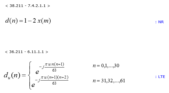
Comparision to LTE PSS
Following is the PSS sequence generation formula for NR PSS and LTE PSS. As you see here, NR PSS is a kind of m-Sequence whereas LTE PSS is a kind of Zadoff-chu sequence.
Sequence Generation Algorithm
NR PSS sequence is generated by the following formula. Unless you are the one who need to implement this, you may not need to understand every details of this formula. But at least it would be good to know of the major factors to determine the sequence. Followings are some highlights about this sequence.
- The sequence is determined by NID(2) as in LTE.

PCI to PSS,SSS Converter
Following is the formula to convert PCI to PSS,SSS. N_cell_ID indicates PCI, N_ID_2 indicates PSS and N_ID_1 indicates SSS
PSS,SSS to PCI Converter
Following is the formula to convert PSS,SSS to PCI. N_cell_ID indicates PCI, N_ID_2 indicates PSS and N_ID_1 indicates SSS
Reference
[1] 38.211 NR;Physical channels and modulation(Release 15)