|
|
||
|
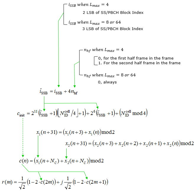
PBCH DMRS is a special type of physical layer signal which functions as a reference signal for decoding PBCH. In LTE (at least in TM1, 2, 3, 4), we don't need this kind of special DMRS for PBCH because we can use CRS(Cell Specific Reference Signal) for PBCH decoding. However, in 5G/NR there is no CRS. That's why we need the DMRS dedicated for PBCH decoding. Sequence GenerationFollowing is the equation to generate PBCH DMRS. As in many other Physical Layer Signal, it is generated by Pseudo Random Sequence, but the part unique for PBCH DMRS is c_init(initialization value). As you see below, the initialization value is made up of various components like Physical Cell ID, SSB Index and Half Frame Number. That is, by decoding this DMRS UE can figure out SSB Index and Half Frame.
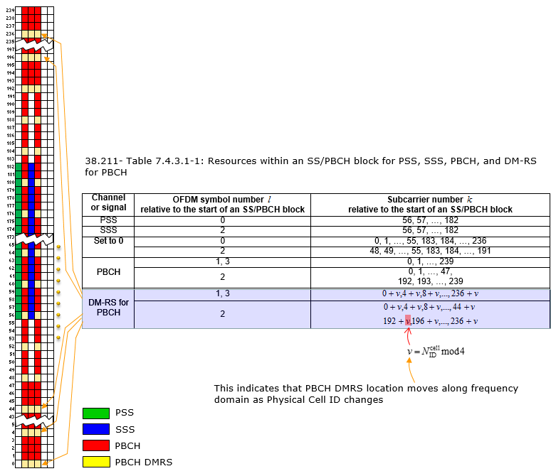
The sequence generation begins with the determination of the SS/PBCH block index iSSB, which is either the two least significant bits (LSB) when Lmax equals 4, or the three LSB when Lmax is 8 or 64. The half-frame number nhf is considered next, which is dependent on Lmax. For Lmax equals 4, nhf changes value within the frame from 0 to 1. For Lmax equals 8 or 64, nhf is always 0. The value iSSB is then calculated by adding 4nhf to the initial lSSB. The initialization sequence cinit is computed using the formula combining iSSB, the physical cell ID NIDcell, and constants in a specified manner involving bitwise shifts and additions. Two sequences x1(n) and x2(n) are created using a pseudo-random number generation method defined by the given polynomials. The sequences are then combined to produce the scrambling sequence c(n), which is used to scramble the DMRS symbols. Finally, the complex DMRS symbols r(m) are generated using the scrambling sequence c(n), involving complex number calculations with real and imaginary components derived from the sequence c(n). Physical Location (Resource Element Mapping)The physical location (Resource Elements) of PBCH DMRS is determined as below. As you see here, the location shifts in frequency domain according to Physical Cell ID. Following diagram illustrates the resource allocation within an SS/PBCH block which includes signals such as the Primary Synchronization Signal (PSS), Secondary Synchronization Signal (SSS), Physical Broadcast Channel (PBCH), and the Demodulation Reference Signals (DM-RS) for PBCH, as specified in the 3GPP TS 38.211.
It outlines the OFDM symbol numbers and the corresponding subcarrier numbers for each channel or signal:
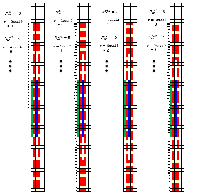
The diagram also shows that the location of the PBCH DMRS moves along the frequency domain as the Physical Cell ID changes. This is indicated by the variable 'v' in the DM-RS resource mapping, which is calculated as a function of the physical cell ID modulo 4. Location Shift by Physical Cell IDAs mentioned above, the array of PBCH DMRS shifts vertically (i.e, in frequency domain) with Physical Cell ID in a manner shown below. Following diagram depicts how the PBCH DMRS array shifts vertically, that is, in the frequency domain, with different Physical Cell IDs. This shift occurs in a pattern as explained below.
For each Physical Cell ID NIDcell, the value of 'v' is determined by taking NIDcell modulo 4. Depending on the result, which ranges from 0 to 3, the PBCH DMRS shifts its position vertically in the grid. The diagrams show the shift for Physical Cell IDs from 0 to 7, illustrating the following patterns:
Each column in the image corresponds to a specific Physical Cell ID and demonstrates the corresponding shift in the PBCH DMRS location. This shifting mechanism is crucial for the UE to identify the correct Physical Cell ID during cell search and synchronization processes.
Reference[1]
|
||